EP1736766A2 - Procédé destiné à la manipulation et à la vérification d'outils et dispositif destiné à l'exécution du procédé - Google Patents
Procédé destiné à la manipulation et à la vérification d'outils et dispositif destiné à l'exécution du procédé Download PDFInfo
- Publication number
- EP1736766A2 EP1736766A2 EP06012663A EP06012663A EP1736766A2 EP 1736766 A2 EP1736766 A2 EP 1736766A2 EP 06012663 A EP06012663 A EP 06012663A EP 06012663 A EP06012663 A EP 06012663A EP 1736766 A2 EP1736766 A2 EP 1736766A2
- Authority
- EP
- European Patent Office
- Prior art keywords
- test
- test substrate
- substrate
- sound
- sorting
- Prior art date
- Legal status (The legal status is an assumption and is not a legal conclusion. Google has not performed a legal analysis and makes no representation as to the accuracy of the status listed.)
- Withdrawn
Links
Images


Classifications
-
- B—PERFORMING OPERATIONS; TRANSPORTING
- B07—SEPARATING SOLIDS FROM SOLIDS; SORTING
- B07C—POSTAL SORTING; SORTING INDIVIDUAL ARTICLES, OR BULK MATERIAL FIT TO BE SORTED PIECE-MEAL, e.g. BY PICKING
- B07C5/00—Sorting according to a characteristic or feature of the articles or material being sorted, e.g. by control effected by devices which detect or measure such characteristic or feature; Sorting by manually actuated devices, e.g. switches
- B07C5/34—Sorting according to other particular properties
-
- G—PHYSICS
- G01—MEASURING; TESTING
- G01N—INVESTIGATING OR ANALYSING MATERIALS BY DETERMINING THEIR CHEMICAL OR PHYSICAL PROPERTIES
- G01N29/00—Investigating or analysing materials by the use of ultrasonic, sonic or infrasonic waves; Visualisation of the interior of objects by transmitting ultrasonic or sonic waves through the object
- G01N29/04—Analysing solids
- G01N29/045—Analysing solids by imparting shocks to the workpiece and detecting the vibrations or the acoustic waves caused by the shocks
-
- G—PHYSICS
- G01—MEASURING; TESTING
- G01N—INVESTIGATING OR ANALYSING MATERIALS BY DETERMINING THEIR CHEMICAL OR PHYSICAL PROPERTIES
- G01N29/00—Investigating or analysing materials by the use of ultrasonic, sonic or infrasonic waves; Visualisation of the interior of objects by transmitting ultrasonic or sonic waves through the object
- G01N29/14—Investigating or analysing materials by the use of ultrasonic, sonic or infrasonic waves; Visualisation of the interior of objects by transmitting ultrasonic or sonic waves through the object using acoustic emission techniques
-
- G—PHYSICS
- G01—MEASURING; TESTING
- G01N—INVESTIGATING OR ANALYSING MATERIALS BY DETERMINING THEIR CHEMICAL OR PHYSICAL PROPERTIES
- G01N29/00—Investigating or analysing materials by the use of ultrasonic, sonic or infrasonic waves; Visualisation of the interior of objects by transmitting ultrasonic or sonic waves through the object
- G01N29/22—Details, e.g. general constructional or apparatus details
- G01N29/225—Supports, positioning or alignment in moving situation
-
- G—PHYSICS
- G01—MEASURING; TESTING
- G01N—INVESTIGATING OR ANALYSING MATERIALS BY DETERMINING THEIR CHEMICAL OR PHYSICAL PROPERTIES
- G01N29/00—Investigating or analysing materials by the use of ultrasonic, sonic or infrasonic waves; Visualisation of the interior of objects by transmitting ultrasonic or sonic waves through the object
- G01N29/22—Details, e.g. general constructional or apparatus details
- G01N29/26—Arrangements for orientation or scanning by relative movement of the head and the sensor
- G01N29/27—Arrangements for orientation or scanning by relative movement of the head and the sensor by moving the material relative to a stationary sensor
-
- G—PHYSICS
- G01—MEASURING; TESTING
- G01N—INVESTIGATING OR ANALYSING MATERIALS BY DETERMINING THEIR CHEMICAL OR PHYSICAL PROPERTIES
- G01N29/00—Investigating or analysing materials by the use of ultrasonic, sonic or infrasonic waves; Visualisation of the interior of objects by transmitting ultrasonic or sonic waves through the object
- G01N29/34—Generating the ultrasonic, sonic or infrasonic waves, e.g. electronic circuits specially adapted therefor
- G01N29/348—Generating the ultrasonic, sonic or infrasonic waves, e.g. electronic circuits specially adapted therefor with frequency characteristics, e.g. single frequency signals, chirp signals
-
- G—PHYSICS
- G01—MEASURING; TESTING
- G01N—INVESTIGATING OR ANALYSING MATERIALS BY DETERMINING THEIR CHEMICAL OR PHYSICAL PROPERTIES
- G01N29/00—Investigating or analysing materials by the use of ultrasonic, sonic or infrasonic waves; Visualisation of the interior of objects by transmitting ultrasonic or sonic waves through the object
- G01N29/44—Processing the detected response signal, e.g. electronic circuits specially adapted therefor
- G01N29/46—Processing the detected response signal, e.g. electronic circuits specially adapted therefor by spectral analysis, e.g. Fourier analysis or wavelet analysis
-
- G—PHYSICS
- G01—MEASURING; TESTING
- G01N—INVESTIGATING OR ANALYSING MATERIALS BY DETERMINING THEIR CHEMICAL OR PHYSICAL PROPERTIES
- G01N2291/00—Indexing codes associated with group G01N29/00
- G01N2291/02—Indexing codes associated with the analysed material
- G01N2291/023—Solids
- G01N2291/0237—Thin materials, e.g. paper, membranes, thin films
-
- G—PHYSICS
- G01—MEASURING; TESTING
- G01N—INVESTIGATING OR ANALYSING MATERIALS BY DETERMINING THEIR CHEMICAL OR PHYSICAL PROPERTIES
- G01N2291/00—Indexing codes associated with group G01N29/00
- G01N2291/26—Scanned objects
- G01N2291/263—Surfaces
- G01N2291/2632—Surfaces flat
-
- G—PHYSICS
- G01—MEASURING; TESTING
- G01N—INVESTIGATING OR ANALYSING MATERIALS BY DETERMINING THEIR CHEMICAL OR PHYSICAL PROPERTIES
- G01N2291/00—Indexing codes associated with group G01N29/00
- G01N2291/26—Scanned objects
- G01N2291/269—Various geometry objects
- G01N2291/2697—Wafer or (micro)electronic parts
Definitions
- the invention relates to a method for handling and testing silicon wafers for solar cell production according to the preamble of claim 1 and to an apparatus for carrying out the method according to the preamble of claim 16.
- silicon wafers semiconductor wafers
- semiconductor wafers semiconductor wafers
- silicon wafers semiconductor wafers
- silicon wafers are delivered in packets to, for example, 50 or 100 pieces from the manufacturer of the solar cells.
- Silicon wafers of different qualities can be present in one package.
- the silicon wafers may, for example, have hairline cracks, have faulty contours or have errors in the imprint and color differences.
- the silicon wafers may have suffered transport damage. So far, the manufacturer of the solar cells, a manual input verification of the supplied silicon wafers is performed, with a manual removal of individual silicon wafers from the packages takes place.
- a test person checks whether there are breakouts on the contour and performs a color classification. To determine if the delivered Silicon discs have invisible hairline cracks, the test person puts the silicon wafer to be tested, for example by shaking in a vibration. This causes a sound emission by the vibrated silicon wafer. On the basis of the sound emitted, the test person recognizes whether it is a hair-crack-free or a defective silicon wafer and then decides whether it is waste or a recyclable silicon wafer. The recyclable silicon wafers are usually stored again a package and z. B. sorted by color supplied to the further manufacturing process for the solar cells.
- a device for hair crack inspection of silicon wafers for the formation of solar cells in which a thin silicon wafer to be examined by means of a recording device is handled and is acted upon by a sound generator with sound. Opposite the sound generator, a sensor is arranged. The transducer receives the sound that is emitted by the silicon wafer to be tested and transmits a measured value to an evaluation device.
- the specified device has not been proven in terms of their function. Reliable detection of damaged silicon wafers was not possible. In addition, such a test method still requires manual examination of the remaining test criteria by a test person.
- the object of the invention is to provide an automated handling and testing method for workpieces, especially flat plate-like workpieces such.
- silicon wafers specify, with the various test criteria can be processed easily and automatically.
- a high inspection reliability and a reliable sorting should be done.
- the invention should allow a cost-effective and reliable entrance examination.
- the silicon wafers have an approximately square peripheral contour with an edge length of z. B. 200 mm.
- the silicon wafers are monocrystalline or polycrystalline plates, which may differ in color. For example, the plates tend to turn reddish, greenish or bluish. In solar cell production, however, it is desirable to integrate only the same color silicon plates in a solar cell, as this significantly improves the visual appearance of the solar cell. Thus, sorting by color is required.
- the silicon wafers a certain surface image, z. B. consisting of interconnects or different etches or imprinted.
- the examination of the accuracy of the surface image must be reliable, so as not to allow defective silicon wafers to enter the subsequent manufacturing process. In addition, it may happen that the silicon wafers, in particular silicon wafers of inferior quality, have breakouts or contour defects. Such an occurrence of outbreaks or contour errors must lead to the corresponding silicon wafer reliably being recognized as rejected and sorted out.
- Another test criterion is the test for hairline cracks, which are not easily visually recognizable.
- test substrate 100 (see FIG. 2) is used in general terms for the silicon wafer.
- test substrate 100 further test criteria and / or sorting criteria are conceivable, which can be processed advantageously with the inventive method.
- the hairline crack test according to the invention is based on a sound measurement of a sound sent by a vibrating test substrate 100.
- the emitted sound has, depending on the geometry of the test substrate 100 and the material properties of the test substrate 100 characteristic properties z. B. in terms of its temporal amplitude curve and / or its frequency, which are measured and compared in an evaluation unit with a reference signal / reference template. Deviations from the characteristic test substrate sound (reference signal / reference template) can be used as an indicator of an error, eg. B. used a hairline crack.
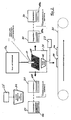
- a first method step delivered test substrates 100 (silicon wafers) are removed from a delivery package and placed in a first storage container as a stack. Individual test substrates 100 are automatically picked up from the storage container by means of a handling device 10 (cf., FIG. 2), for example removed individually from the test substrate stack by means of a suction gripper, so that an automatic pick-up 1 of the substrate 100 to be tested takes place. After automatic picking 1 of the substrate 100 to be tested, the substrate 100 to be tested is checked for a first quality feature in a first test operation 2. The first quality feature is z. B is the hairline freedom test based on a sound measurement of a characteristic "sound image" of the test substrate 100, which will be further explained below.
- test substrate 100 is fed by means of the handling device 10 to a second test operation 3 and / or sorting operation. If the test of the first test operation 2 is negative, the test substrate 100 is fed to a first tray 4 in which scrap is collected based on the first test criterion. Particularly preferably, the degree of filling of the tray 4 is monitored and the tray 4 is replaced by an empty tray 4 when fully filled.
- a color test of the test substrate 100 is performed, which is done by means of industrial image processing.
- a data memory different color comparison and color tolerance values are stored here.
- the surface color of the substrate 100 to be tested is compared with the stored color tolerances and / or color values. If the test gives the surface color, the tested substrate 100 corresponds to the color requirement, the test substrate 100 is fed to a collection device corresponding to the color and / or optionally to another test operation 4.
- the test substrates 100 are sorted according to color value recognized by color values stored in shelves, the test substrates thus undergo a color sorting. If necessary, the test substrates 100 are supplied to a further test operation 4 or forwarded to a subsequent production process for solar cells. If the examination of the test operation 3 is negative, the test substrate 100 is fed to a further tray 5 (reject tray), which in turn may be monitored for filling.
- Particularly preferably 3 further checks of optically detectable features can be carried out in the second test operation, wherein z. B. the peripheral contour and / or the surface image z. B. with regard to the tracks by means of industrial image recording and processing methods recorded, tested and evaluated.
- test criteria of the substrate 100 to be tested can be processed. For example, this can be the weight, or comparable test criteria.
- reject substrates are transferred to a corresponding reject stack 6 and deposited.
- an automatic transfer of the found to be in order substrate 100 to a subsequent process eg. B. the production process of solar cells.
- This method step is identified by the reference numeral 7. After passing the order for okay The automated inspection and handling process according to the invention has been completed.
- sorting operations are carried out in terms of time after the test operation (s).
- the test substrate 100 is preferably produced by means of a handling device 10, e.g. B. a suction pad 10 (see Figure 2) moves from one test station to the next.
- the handling device 10 is z. B. connected to a track 10a.
- the trajectory 10a is z.
- a temporary separation of the test substrate 100 from the handler 10 and a deposition of the test substrate 100 in a test station may occur during a particular test operation.
- the test substrate 100 is moved into a test chamber (not shown) in which a sound sensor 11 (see Fig. 2) is arranged.
- the test substrate 100 here: the silicon wafer
- the test substrate 100 is set in oscillation, so that a sound emission from the test substrate 100 to the sound sensor 11 takes place.
- the vibration excitation can be done in various ways.
- the test substrate 100 may be provided with an excitation body, e.g. a vibration exciter, are brought into contact, so that a structure-borne noise from the excitation body or vibrator to the test substrate 100 transmits and thus puts this into vibration.
- an excitation body e.g. a vibration exciter
- the vibration exciter is in communication with a frequency generator, so that the vibration exciter vibration with defined temporal and amplitude moderate Course on the test substrate 100 in direct contact with this transmits.
- the test substrate 100 is set in vibration and emits a sound emission, which is picked up by the sound sensor 11, which acts as a measuring sensor, and fed to a signal processing device, eg, a measuring and evaluation unit 23.
- a reference signal template is stored, which is characteristic of a defect-free, ie, hairline-free substrate.
- the sound emitted by the test substrate 100 being tested is compared with the reference template. When exceeding critical deviation limits of the recorded sound image of the substrate to be tested in comparison to the reference template, the substrate to be tested is classified as defective.
- the handling device 10 as a gripping device 10, z. B. formed as a suction pads with one or more suction cups, which hold the test substrate 100 by means of negative pressure.
- a single suction gripper which holds the test substrate 100 approximately in the middle, has proven particularly useful.
- an arrangement of several suction pads is conceivable.
- the negative pressure by means of the test substrate 100 is held by the suction pad 10, for a certain time, starting from a nominal negative something lower, ie to increase the absolute pressure somewhat, so that the test substrate 100 solves something from the suction pad, but can not completely separate from the suction pad 10.
- the suction pad is preferred abruptly, again with a lower pressure, z. B. the nominal negative pressure, so that a jerky suction of the test substrate 100 to a stop, z. B. the suction cup bottom occurs.
- the stopper By hitting the stopper, the test substrate 100 undergoes vibration excitation, whereby sound is emitted in the direction of the sound sensor 11.
- this sound has a characteristic frequency profile and / or a characteristic amplitude-time profile. At least one of these courses is picked up by the sound sensor 11 and fed to an evaluation device (not shown), in which the recorded "sound image” is compared with a characteristic "sound image” of a test substrate 100 which has been found to be in good condition.
- the storage devices 4, 5, 6 shown separately in FIG. 1 are combined into a single storage device for broke test substrates.
- a time-decaying vibration of the test substrate 100 is particularly preferably detected by means of the sound sensor 11.
- the device has a traversing unit 10a, on which a gripping means, for. B. the handling device 10, which is designed as a suction pad, is arranged.
- the traversing unit 10a and the handling device 10 form a so-called handling device.
- the moving unit 10a removes a test substrate 100 from the storage container 20 by means of the suction gripper 10 and feeds it to a test chamber 21.
- the direct vibration excitation of the test substrate 100 for example, as described above, by the suction pad 10 itself.
- the acoustic sensor 11 is arranged in the test chamber 21, the acoustic sensor 11 is arranged.
- the acoustic sensor 11 receives the signal emitted from the test substrate 100 Sound, which preferably lies in the audible range, and supplies a corresponding measurement signal to a measurement and evaluation unit 23.
- a measurement and evaluation unit 23 an evaluation of the measurement signal takes place in which it is compared with a reference signal of a reference test substrate 100.
- a device has a camera 24 by means of which a check of the test substrate 100 for optical quality features, for. B. on accuracy of the surface image, accuracy of the trimming contour and / or affiliation to a particular color value.
- the camera 24 is connected to an image processing device 25, in which a camera signal is compared with one or more reference optical signals of a reference test substrate.
- the image processing device 25 is integrated in the camera 24.
- the camera 24 is arranged, for example, above a storage container 20 in which the test substrates 100 are arranged in a stack. This makes it possible, in each case, to subject the uppermost test substrate of a storage container already before receiving the test substrate by the handling device 10 to a test for optical quality features.
- the storage containers 20 preferably have means for monitoring supply and signaling means for displaying the filling level of the storage container 20. Furthermore, the device has at least one storage container 30 for receiving reject test substrates 100a.
- a plurality of storage containers 30 are provided, so that a sorting of the reject test substrates 100a can be carried out by error type. For example, in a first storage container all reject test substrates 100a are arranged, in which the sound check for hairline cracks has been negative. In a second storage container For example, all those reject test substrates 100a may be stored which have contour errors, e.g. B. Outbreaks or errors in the surface image or the like. Thus, it is easier to detect the frequency of occurrence of a particular type of error and, if necessary, to send the reject test substrates 100a back to the supplier in order of errors.
- contour errors e.g. B. Outbreaks or errors in the surface image or the like.
- the device advantageously has interfaces to a quality management system (not shown) in which the test result of each test substrate can be stored for the purpose of documentation.
- the device according to the invention expediently has at least one conveying means 31, by means of the test substrates 100, which have fulfilled all test criteria of further processing, for. B. manufacturing process of a solar cell can be supplied.
- the storage container 30 preferably also have a fill level monitoring and corresponding signal means for displaying the fill level storage container.
- the device according to the invention has means for vibrational excitation of the test substrate 100 in the test chamber 21.
- the means for vibrational excitation z. Example, an excitation body (not shown), which can be brought to the vibration excitation of the test substrate 100 in direct contact with the test substrate 100, so that z. B. structure-borne noise of the excitation body can be transferred to the test substrate 100.
- the means for vibratory excitation of the test substrate 100 may be, for example, a clapper or a percussion hammer or the like, by means of which a direct mechanical vibration excitation of the test substrate 100 can take place.
- the handling device 10 is designed as a vacuum gripper (suction gripper), which with at least one suction cup, the test substrate 100 can grab.
- a control device for controlling the negative pressure of the vacuum gripper is present, by means of which in particular short-term vacuum fluctuations on the suction pads are exercisable, so that by means of the suction pad itself a vibration excitation of the test substrate 100 can take place.
- the vacuum gripper 10 performs functional bundling both with regard to the test substrate transport (material transport) and with regard to the vibration excitation of the test substrate 100.
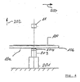
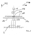
- FIGS. 3 to 6 show a second embodiment of a device according to the invention for carrying out the method. Elements of the same function in comparison to the embodiment according to FIG. 2 are identified by the same reference symbols.
- the device according to the invention has a conveyor 10a in the form of a parallel belt conveyor, on which the test substrates 100 can be transported along a conveying direction 200.
- a traversing unit 201 In a front view between a pair of conveyor belts 10b and below the test substrates 100 there is a traversing unit 201, which can be moved in one direction 202, in particular vertically to the conveying direction 200.
- the movement unit 201 carries a vibration exciter 203, which in particular can be coupled to the test substrate 100 via a suction cup 204, which acts as a vibration coupling element.
- the sound sensor 11 Spaced above the test substrate 100, the sound sensor 11 is arranged.
- a test substrate 100 is disposed above the vibrator 203, by means of the track 201, the vibrator 203 is raised together with the suction cup 204 by a height h, so that the suction cup 204 comes into contact with the underside of the test substrate 100 and this lifts a piece of the conveyor 10a.
- the test substrate 100 can vibrate freely by the conveyor belt pair 10b.
- a vibration signal 205 defined with respect to the frequency and / or amplitude characteristic is transmitted to the test substrate 100 by means of the vibration generator 203 via the suction cup 204.
- the test substrate 100 is thereby excited to oscillate and emits sound waves 206, which are received by the acoustic sensor 11.
- the oscillator 203 and the suction cup 204 are moved down again by the height h so that the test substrate 100 again rests on the conveyor 10a and is transported further in the conveying direction 200 ,
- This embodiment according to FIGS. 3 to 6 also realizes the principle according to the invention, a defined oscillation pattern, i. To enter a defined excitation vibration directly into the test substrate 100 and to record a sound emission of the test substrate 100 by means of an acoustic sensor 11.
- the coupling of the test substrate 100 with the oscillator 203 may take place via a suction cup 204 also via other coupling elements, eg a tripod or other means suitable for supporting test substrates 100. It is essential that the mechanical oscillation provided by the oscillator 203 is transmitted directly to the test substrate 100 without the interposition of an indirect medium, such as air, for example.
- the direct initiation of vibration of the excitation vibration into the test substrate 100 may cause environmental influences, e.g. different ambient air pressure and humidity conditions as well as, for example, the influence of noise sources in the environment are switched off. It has been particularly preferred that the loading of the test substrate 100 with a so-called frequency sweep, i. a timed waveform within the limits of e.g. 5 kHz to 25 kHz, in particular 7 kHz to 20 kHz, proven. It is particularly advantageous to choose a frequency and amplitude curve that is chosen differently from an ideal sinusoidal curve. In particular, for example, trapezoidal or trapezoidal, rectangular or rectangular-like, sawtooth or sawtooth-like or frequency characteristics combined therefrom can be used.
- the evaluation of the sound 206 recorded by the acoustic sensor 11 is then carried out by means of a so-called Fourier analysis. It has been found to be particularly advantageous that with the use of a frequency sweep followed by Fourier analysis for the sound of the acoustic sensor 11 in an effective manner ambient noise are hidden, so that they have no effect on the measurement result.
- the time sequence of the individual test operations 2, 3, 4 shown in FIG. 1 is not to be understood as limiting.
- the individual test operations can also be carried out in a chronologically changed sequence.
- that test operation is advantageously provided, in which a sorting of the test substrates z. B. takes place according to surface colors. This ensures that the sort operation Now test substrates are fed, which have passed through all previous error checking operations positive.
- test substrates silicon wafers
- test result is improved in terms of its constancy and repeatability.
- the method according to the invention and the device according to the invention offer a possibility of testing the test substrates non-destructively and gently for a plurality of test criteria, so that damage and / or destruction of an intact test substrate during the test procedure is precluded.
- the method and the device are suitable to be incorporated into an already existing production line, so that a so-called in-line capability is ensured.
- the invention can be installed both in new production facilities or integrated in addition to existing production facilities.
Landscapes
- Physics & Mathematics (AREA)
- Immunology (AREA)
- Health & Medical Sciences (AREA)
- Chemical & Material Sciences (AREA)
- Analytical Chemistry (AREA)
- Biochemistry (AREA)
- General Health & Medical Sciences (AREA)
- Life Sciences & Earth Sciences (AREA)
- General Physics & Mathematics (AREA)
- Pathology (AREA)
- Acoustics & Sound (AREA)
- Engineering & Computer Science (AREA)
- Signal Processing (AREA)
- Mathematical Physics (AREA)
- Spectroscopy & Molecular Physics (AREA)
- Testing Or Measuring Of Semiconductors Or The Like (AREA)
- Manufacturing Of Magnetic Record Carriers (AREA)
Applications Claiming Priority (1)
| Application Number | Priority Date | Filing Date | Title |
|---|---|---|---|
| DE200510028920 DE102005028920A1 (de) | 2005-06-22 | 2005-06-22 | Verfahren zum Handhaben und Prüfen von Werkstücken sowie Vorrichtung zum Durchführen des Verfahrens |
Publications (2)
| Publication Number | Publication Date |
|---|---|
| EP1736766A2 true EP1736766A2 (fr) | 2006-12-27 |
| EP1736766A3 EP1736766A3 (fr) | 2007-12-05 |
Family
ID=36996488
Family Applications (1)
| Application Number | Title | Priority Date | Filing Date |
|---|---|---|---|
| EP06012663A Withdrawn EP1736766A3 (fr) | 2005-06-22 | 2006-06-20 | Procédé destiné à la manipulation et à la vérification d'outils et dispositif destiné à l'exécution du procédé |
Country Status (2)
| Country | Link |
|---|---|
| EP (1) | EP1736766A3 (fr) |
| DE (1) | DE102005028920A1 (fr) |
Cited By (5)
| Publication number | Priority date | Publication date | Assignee | Title |
|---|---|---|---|---|
| CN104259109A (zh) * | 2014-07-28 | 2015-01-07 | 中国电子科技集团公司第四十八研究所 | 一种步进式硅片品质分选系统 |
| CN107315049A (zh) * | 2017-07-31 | 2017-11-03 | 苏州东菱智能减振降噪技术有限公司 | 一种瓷砖检测仪及检测方法 |
| CN109622392A (zh) * | 2018-12-28 | 2019-04-16 | 温州市天瑞制药机械有限公司 | 一种软胶囊视频自动分拣装置 |
| CN112495824A (zh) * | 2020-11-09 | 2021-03-16 | 温州市凌度电子科技有限公司 | 一种太阳能电板的传输机构 |
| CN113155962A (zh) * | 2021-03-22 | 2021-07-23 | 绍兴柯桥亮剑机械有限公司 | 一种基于超声波的铸件毛刺检测设备及其系统 |
Families Citing this family (6)
| Publication number | Priority date | Publication date | Assignee | Title |
|---|---|---|---|---|
| DE102007010516A1 (de) * | 2007-03-05 | 2008-09-18 | Intego Gmbh | Verfahren zur Identifizierung der Herkunft eines polykristallinen Produkts sowie Vorrichtung mit einer Bilderfassungseinheit zur Erstellung von Produktbildern eines polykristallinen Produkts |
| CN106298568B (zh) * | 2016-07-25 | 2019-04-12 | 河海大学常州校区 | 一种太阳能电池片的灰片的检测方法 |
| CN109894377B (zh) * | 2019-04-01 | 2023-05-23 | 山东九思新材料科技有限责任公司 | 一种皮带输送装置及硅料自动分拣系统 |
| CN110238074B (zh) * | 2019-06-27 | 2022-12-23 | 南京涵铭置智能科技有限公司 | 一种基于色彩识别的纽扣分选机及其分选方法 |
| CN110721928B (zh) * | 2019-10-21 | 2021-02-05 | 武汉纺织大学 | 一种太阳能电池片的色差分选方法及系统 |
| DE102020122008A1 (de) | 2020-08-24 | 2022-02-24 | Bayerische Motoren Werke Aktiengesellschaft | Prüfverfahren, Verwendung sowie Prüfstandsanordnung |
Family Cites Families (7)
| Publication number | Priority date | Publication date | Assignee | Title |
|---|---|---|---|---|
| DE3943133A1 (de) * | 1989-12-28 | 1991-07-18 | Zeuna Staerker Kg | Verfahren zur akustischen pruefung von monolithen auf beschaedigung und vorrichtung zur durchfuehrung des verfahrens |
| US6062084A (en) * | 1999-01-29 | 2000-05-16 | Taiwan Semiconductor Manufacturing Co., Ltd. | Apparatus for detecting wafer edge defects and method of using |
| US6605807B2 (en) * | 2000-06-05 | 2003-08-12 | The Boeing Company | Infrared crack detection apparatus and method |
| JP4349478B2 (ja) * | 2001-02-09 | 2009-10-21 | チューナー株式会社 | 車載用電子装置 |
| DE10150563C1 (de) * | 2001-10-15 | 2003-05-08 | Intermet Neunkirchen Gmbh | Verfahren zur Qualitätsprüfung von Gussteilen |
| DE10345577A1 (de) * | 2003-09-29 | 2005-05-12 | Hans Thoma | Vorrichtung zur Haarrißprüfung von Siliziumscheiben zur Bildung von Solarzellen |
| JP2005142495A (ja) * | 2003-11-10 | 2005-06-02 | Sharp Corp | 基板クラック検査方法、基板クラック検査装置、太陽電池モジュールの製造方法 |
-
2005
- 2005-06-22 DE DE200510028920 patent/DE102005028920A1/de not_active Ceased
-
2006
- 2006-06-20 EP EP06012663A patent/EP1736766A3/fr not_active Withdrawn
Cited By (7)
| Publication number | Priority date | Publication date | Assignee | Title |
|---|---|---|---|---|
| CN104259109A (zh) * | 2014-07-28 | 2015-01-07 | 中国电子科技集团公司第四十八研究所 | 一种步进式硅片品质分选系统 |
| CN107315049A (zh) * | 2017-07-31 | 2017-11-03 | 苏州东菱智能减振降噪技术有限公司 | 一种瓷砖检测仪及检测方法 |
| CN109622392A (zh) * | 2018-12-28 | 2019-04-16 | 温州市天瑞制药机械有限公司 | 一种软胶囊视频自动分拣装置 |
| CN109622392B (zh) * | 2018-12-28 | 2024-05-03 | 浙江天瑞制药机械有限公司 | 一种软胶囊视频自动分拣装置 |
| CN112495824A (zh) * | 2020-11-09 | 2021-03-16 | 温州市凌度电子科技有限公司 | 一种太阳能电板的传输机构 |
| CN112495824B (zh) * | 2020-11-09 | 2022-08-09 | 山西晋通送变电有限公司 | 一种太阳能电板的传输机构 |
| CN113155962A (zh) * | 2021-03-22 | 2021-07-23 | 绍兴柯桥亮剑机械有限公司 | 一种基于超声波的铸件毛刺检测设备及其系统 |
Also Published As
| Publication number | Publication date |
|---|---|
| DE102005028920A1 (de) | 2006-12-28 |
| EP1736766A3 (fr) | 2007-12-05 |
Similar Documents
| Publication | Publication Date | Title |
|---|---|---|
| DE69734106T2 (de) | Verfahren und anordnung zur zerstörungsfreien klassifikation | |
| DE3888403T2 (de) | Verfahren zum Überprüfen von Eiern auf das Vorhandensein von Rissen oder Löchern in den Eierschalen durch Prüfung der Elastizität jener Schalen und Vorrichtung zur Ausführung des Verfahrens. | |
| EP3140062B1 (fr) | Procédé et appareil de contrôle d'un rivet | |
| DE60014387T2 (de) | Verfahren und vorrichtung zur ermittlung der härte eines produkts wie zum beispiel frucht | |
| EP1736766A2 (fr) | Procédé destiné à la manipulation et à la vérification d'outils et dispositif destiné à l'exécution du procédé | |
| CN109142547B (zh) | 一种基于卷积神经网络的声学在线无损检测方法 | |
| AT393198B (de) | Waffelteig, gebackenem backteig oder dergleichen | |
| EP1895297A1 (fr) | Support d'enregistrement de flux numérique, procédé d'enregistrement, et procédé de lecture | |
| WO2004028939A2 (fr) | Dispositif de prehension destine a un dispositif de manipulation et procede d'utilisation correspondant | |
| EP2030895A1 (fr) | Dispositif de remplissage de tablettes surveillé | |
| US11441985B2 (en) | System for analyzing impact and puncture resistance | |
| EP3899486B1 (fr) | Dispositif et procédé de détermination de propriétés mécaniques d'une éprouvette | |
| DE102020211723A1 (de) | Verfahren zum bearbeiten eines wafers und eine chipmessvorrichtung | |
| WO2009130230A1 (fr) | Procédé et dispositif pour la détection non destructrice par ultrasons de défauts à l’intérieur d’un matériau semi-conducteur | |
| EP2317308B1 (fr) | Dispositif et procédé de contrôle de dommages sur un composant | |
| EP3662252B1 (fr) | Dispositif d'analyse d'impact et de résistance à la perforation | |
| CH647332A5 (de) | Richtpresse. | |
| CH705370A1 (de) | Verfahren und Vorrichtung zur Inspektion eines Halbleiterchips vor der Montage. | |
| DE3300259C2 (fr) | ||
| DE1648540A1 (de) | Verfahren und Vorrichtung zur Untersuchung der Dichtigkeit von Gegenstaenden | |
| DE3936163A1 (de) | Verfahren und vorrichtung zur messung der dichtigkeit hermetisch abgeschlossener behaelter | |
| DE102008008276B4 (de) | Vorrichtung und Verfahren zur Detektion von Defekten von mono- oder polykristallinen Siliziumscheiben | |
| DE102017012007A1 (de) | Vorrichtung und Verfahren zur universellen akustischen Prüfung von Objekten | |
| EP0036909A2 (fr) | Procédé de contrôle non-destructif d'éléments de construction | |
| WO2003006983A1 (fr) | Detection de defauts dans des corps en materiaux fragiles |
Legal Events
| Date | Code | Title | Description |
|---|---|---|---|
| PUAI | Public reference made under article 153(3) epc to a published international application that has entered the european phase |
Free format text: ORIGINAL CODE: 0009012 |
|
| AK | Designated contracting states |
Kind code of ref document: A2 Designated state(s): AT BE BG CH CY CZ DE DK EE ES FI FR GB GR HU IE IS IT LI LT LU LV MC NL PL PT RO SE SI SK TR |
|
| AX | Request for extension of the european patent |
Extension state: AL BA HR MK YU |
|
| PUAL | Search report despatched |
Free format text: ORIGINAL CODE: 0009013 |
|
| AK | Designated contracting states |
Kind code of ref document: A3 Designated state(s): AT BE BG CH CY CZ DE DK EE ES FI FR GB GR HU IE IS IT LI LT LU LV MC NL PL PT RO SE SI SK TR |
|
| AX | Request for extension of the european patent |
Extension state: AL BA HR MK YU |
|
| RIC1 | Information provided on ipc code assigned before grant |
Ipc: G01N 29/46 20060101ALI20071031BHEP Ipc: G01N 29/27 20060101ALI20071031BHEP Ipc: G01M 7/02 20060101ALI20071031BHEP Ipc: B07C 5/342 20060101ALI20071031BHEP Ipc: G01N 29/22 20060101ALI20071031BHEP Ipc: G01N 29/34 20060101ALI20071031BHEP Ipc: G01N 29/14 20060101ALI20071031BHEP Ipc: G01N 29/04 20060101AFI20060928BHEP |
|
| 17P | Request for examination filed |
Effective date: 20071203 |
|
| 17Q | First examination report despatched |
Effective date: 20070109 |
|
| AKX | Designation fees paid |
Designated state(s): AT BE BG CH CY CZ DE DK EE ES FI FR GB GR HU IE IS IT LI LT LU LV MC NL PL PT RO SE SI SK TR |
|
| STAA | Information on the status of an ep patent application or granted ep patent |
Free format text: STATUS: THE APPLICATION IS DEEMED TO BE WITHDRAWN |
|
| 18D | Application deemed to be withdrawn |
Effective date: 20081024 |