EP1737077A2 - Elektrischer Verbinder mit Federkontaktanschluss mit Doppelkontaktfunktion - Google Patents
Elektrischer Verbinder mit Federkontaktanschluss mit Doppelkontaktfunktion Download PDFInfo
- Publication number
- EP1737077A2 EP1737077A2 EP06076183A EP06076183A EP1737077A2 EP 1737077 A2 EP1737077 A2 EP 1737077A2 EP 06076183 A EP06076183 A EP 06076183A EP 06076183 A EP06076183 A EP 06076183A EP 1737077 A2 EP1737077 A2 EP 1737077A2
- Authority
- EP
- European Patent Office
- Prior art keywords
- spring
- arm
- contact
- terminal
- primary
- Prior art date
- Legal status (The legal status is an assumption and is not a legal conclusion. Google has not performed a legal analysis and makes no representation as to the accuracy of the status listed.)
- Withdrawn
Links
Images



Classifications
-
- H—ELECTRICITY
- H01—ELECTRIC ELEMENTS
- H01R—ELECTRICALLY-CONDUCTIVE CONNECTIONS; STRUCTURAL ASSOCIATIONS OF A PLURALITY OF MUTUALLY-INSULATED ELECTRICAL CONNECTING ELEMENTS; COUPLING DEVICES; CURRENT COLLECTORS
- H01R13/00—Details of coupling devices of the kinds covered by groups H01R12/70 or H01R24/00 - H01R33/00
- H01R13/02—Contact members
- H01R13/10—Sockets for co-operation with pins or blades
- H01R13/11—Resilient sockets
- H01R13/113—Resilient sockets co-operating with pins or blades having a rectangular transverse section
-
- H—ELECTRICITY
- H01—ELECTRIC ELEMENTS
- H01R—ELECTRICALLY-CONDUCTIVE CONNECTIONS; STRUCTURAL ASSOCIATIONS OF A PLURALITY OF MUTUALLY-INSULATED ELECTRICAL CONNECTING ELEMENTS; COUPLING DEVICES; CURRENT COLLECTORS
- H01R13/00—Details of coupling devices of the kinds covered by groups H01R12/70 or H01R24/00 - H01R33/00
- H01R13/02—Contact members
- H01R13/10—Sockets for co-operation with pins or blades
- H01R13/11—Resilient sockets
- H01R13/114—Resilient sockets co-operating with pins or blades having a square transverse section
Definitions
- the present invention relates to electrical connectors, and more particularly to female connectors having a spring contact for electrically interfacing a male blade terminal. Still more particularly, the present invention relates to an electrical connector having a dual contact function spring contact.
- Electrical connectors having spring contact terminals perform well to provide electrical connection with respect to an inserted male blade terminal; however, certain deficiencies are present. For example, should the spring contact terminal become deformed (as for example because a male blade terminal was, itself, bent and then insertionally forced so as to thereby cause the deformation), then there is some likelihood that the electrical connection between the spring contact terminal and the male blade terminal will fail.
- the present invention is an electrical connector having disposed therewithin a spring contact terminal which is insensitive to deformation by providing a dual contact function thereto.
- the improved electrical connector according to the present invention includes an electrical conductor body having a general box-shape terminal cavity defined by an upper wall, a lower wall and a pair of sidewalls, wherein internally disposed is at least one dual contact function spring contact terminal.
- a dual contact function spring contact terminal originates at a primary nose formed integrally of either the upper or the lower wall, at the entry port of the electrical conductor body.
- an arm is integrally formed of the conductor body which bends 180 degrees so as to form an initial arm portion disposed within the terminal cavity and extending, in spaced relation from the subject upper or lower wall, rearwardly from the primary nose in parallel relation to the subject upper or lower wall.
- a contact portion of the arm is generally medially disposed within the terminal cavity via a primary spring of the arm which spans between the initial portion and a forward end of the contact portion of the arm.
- At the opposite, rearward end of the contact portion of the arm is a secondary nose formed of the arm so as to provide a 180 degree bend therein.
- a secondary spring of the arm Connected to the secondary nose is a secondary spring of the arm which bends toward, and contacts, at a terminus thereof, the subject upper or lower wall. Disposed in opposition to the contact portion of the arm is a terminal contact formed of the electrical conductor body (this may be alternatively in another embodiment, simply the contact portion of the arm of another dual contact function spring contact terminal).
- a male blade terminal is inserted into the electrical conductor body of the electrical connector, wherein, as the male blade terminal is inserted, it abuts the primary spring and the opposing terminal contact, causing the primary spring to resiliently bend toward the subject upper or lower wall.
- the male blade terminal slides further along the contact portion of the arm and the opposing terminal contact, and the secondary spring also becomes resiliently bent toward the subject upper or lower wall.
- the male blade terminal is in good electrical contact with the contact portion of the arm and the terminal contact as a result of the dual spring action of the primary and secondary springs.
- the primary spring and the secondary spring perform independently of each other. Accordingly, in the event the primary spring should become damaged, as for example if the male blade terminal untowardly bent the primary spring, then the secondary spring will function normally and independently of the primary spring so as to provide excellent electrical contact of an inserted male blade terminal with the contact portion of the arm and the opposing terminal contact.
- a relief spring formed in the subject upper or lower wall where the arm terminus abuts the subject upper or lower wall.
- a pair of dual contact function spring contact terminals is provided.
- An upper dual contact function spring contact terminal is formed of an upper arm via an upper primary nose
- a lower dual contact function spring contact terminal is formed of a lower arm via a lower primary nose, wherein the upper and lower arms are mirrors of each other.
- an electrical connector having disposed therewithin at least one dual contact function spring contact terminal, wherein primary and secondary springs thereof function independently of each other.
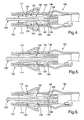
- Figures 1 through 6 depict aspects of a first embodiment
- Figures 7 through 10 depict aspects of a second embodiment, of an electrical connector 100, 100' having disposed therewithin at least one dual function contact spring terminal 102, 102', 102" according to the present invention.
- the electrical connector 100 is composed of a preferably (but not necessarily) single piece, metal sheet which is stamped to provide an electrical conductor body 104 having a forward end 104a and a rearward end 104b and, integrally connected to the rearward end, a wiring engagement member 106 including a bare wire crimp portion 106a and a wire jacket crimp portion 106b.
- the electrical conductor body 104 is encapsulated in a plastic or other suitable insulator 108 in a manner known in the art, a portion of which is shown by way of example at Figure 3.
- the electrical conductor body 104 has a general box-shape, forming therewithin a terminal cavity 110 defined by an upper wall 112, an oppositely disposed lower wall 114 and a pair of mutually opposed sidewalls 116, 118, wherein internally disposed are upper and lower dual contact function spring contact terminals 102, 102'.
- the upper dual contact function spring contact terminal 102 is composed of an upper arm 124 originating at an upper primary nose 120 that is formed integrally of the upper wall 112 at an entry port 122 of the electrical conductor body 104.
- the upper arm 124 is integrally formed of the electrical conductor body 104 which bends 180 degrees so as to form an initial upper arm portion 126 disposed within the terminal cavity 110 and extending, in close spaced relation from the upper wall 112, rearwardly from the upper primary nose in parallel relation to the upper wall.
- An upper contact portion 128 of the upper arm 124 is generally medially disposed within the terminal cavity 110 via an upper primary spring 130 of the upper arm which spans between the initial upper arm portion 126 and a forward end of the upper contact portion 128 of the upper arm. Resiliency of the upper primary spring 130 may be enhanced by preferably providing a centrally disposed upper primary spring slot 132 formed thereat in the upper arm.
- an upper secondary nose 134 formed of the upper arm so as to provide a 180 degree bend therein.
- Extending from the upper secondary nose 134 is an upper secondary spring 136 of the upper arm which bends toward, and contacts at an upper arm terminus 124a of the upper arm, the upper wall 112. Resiliency of the upper secondary spring 136 may be adapted to suit a particular application, if desired, by providing a centrally disposed upper secondary spring slot or by widening or narrowing the upper arm thereat.
- an upper relief spring 140 formed in the upper wall 112 where the upper arm terminus 124a abuts the upper wall.
- the lower dual contact function spring contact terminal 102' is composed of a lower arm 124' originating at a lower primary nose 120' formed integrally of the lower wall 114 at the entry port 122 of the electrical conductor body 104.
- the lower arm 124' is integrally formed of the conductor body 104 which bends 180 degrees so as to form an initial lower arm portion 126' disposed within the terminal cavity 110 and extending, in closely spaced relation from the lower wall 114, rearwardly from the lower primary nose in parallel relation to the lower wall.
- a lower contact portion 128' of the lower arm 124' is generally medially disposed within the terminal cavity 110 via a lower primary spring 130' of the lower arm which spans between the initial lower arm portion 126' and a forward end of the lower contact portion 128' of the lower arm.
- the upper and lower contact portions 128, 128' are disposed in mutually opposing relation.
- Resiliency of the lower primary spring 130' may be enhanced by preferably providing a centrally disposed lower primary spring slot 132' formed thereat in the lower arm.
- a lower secondary nose 134' formed of the lower arm so as to provide a 180 degree bend therein.
- a lower secondary spring 136' Extending from the lower secondary nose 134' is a lower secondary spring 136' of the lower arm which bends toward, and contacts at the lower arm terminus 124a' of the lower arm, the lower wall 114.
- Resiliency of the lower secondary spring 136' may be adapted to suit a particular application, if desired, by providing a centrally disposed upper secondary spring slot or by widening or narrowing the lower arm thereat.
- a lower relief spring 140' formed in the lower wall 114 where the lower arm terminus 124a' abuts the lower wall.
- a male blade terminal 200 is inserted into the electrical conductor body 104 of the electrical connector, wherein, as the male blade terminal is inserted, it abuts with the upper and lower primary springs 130, 130', causing the upper primary spring to resiliently bend toward the upper wall 110, and the lower primary spring to resiliently bend toward the lower wall 112.
- the male blade terminal slides along the upper contact portion 128 of the upper arm 124 and the lower contact portion 128' of the lower arm 124', the upper secondary spring 136 is resiliently bent toward the upper wall 112 and the lower secondary spring 136' is resiliently bent toward the lower wall 114.
- the male blade terminal Upon full insertion of the male blade terminal, as shown at Figure 4, the independent and dual spring action of the upper and lower primary springs and upper and lower secondary springs, the male blade terminal is in good electrical contact with the upper and lower contact portions, which conform to the male blade terminal, and, consequently, with the electrical conductor body 104.
- the upper primary spring 130 and upper secondary spring 136 of the upper dual contact function spring contact terminal 102 perform independently of each other to resiliently locate the upper contact portion 128 of the upper arm 124; and likewise, the lower primary spring 130' and lower secondary spring 136' of the lower dual contact function spring contact terminal 102' perform independently of each other to resiliently locate the lower contact portion 128' of the lower arm 124'.
- the upper and lower relief springs 140, 140' deform when a male blade terminal greater than a predetermined thickness is inserted into the electrical connector in order to prevent over forcing of the upper and lower secondary springs 136, 136'.
- a predetermined male blade thickness 0.64 mm.
- Figure 5 if a male blade terminal 200' having a thickness of 0.80 mm. is inserted into the conductor body cavity, then the incremented upper and lower secondary spring tensions are relieved by resilient bending of the upper and lower relief springs 140, 140'.
- the primary spring 130' of the lower dual contact function spring contact terminal 102' has been bendingly damaged by some untoward event, yet the lower secondary spring 136' is independently and normally functioning to provide good electrical contact of the male blade terminal 200 with the upper and lower contact portions 128, 128' and, consequently, with the electrical conductor body 104.
- the electrical connector 100' is composed of a preferably (but not necessarily) single piece of metal sheet which is stamped to provide an electrical conductor body 104' having a forward end 104a' and a rearward end 104b' and, integrally connected to the rearward end, a wiring engagement member which, although not shown in Figures 7 through 10, is identical to that shown as 106 in Figure 1 and includes the aforedescribed bare wire crimp portion 106a and a wire jacket crimp portion 106b.
- the electrical conductor body 104' is encapsulated in a plastic or other suitable insulator in a manner known in the art (depicted by way of example at Figure 3).
- the electrical conductor body 104' has a general box-shape, forming therewithin a terminal cavity 110' defined by an upper wall 112', an oppositely disposed lower wall 114' and a pair of mutually opposing sidewalls 116', 118', wherein internally disposed is a single dual contact function spring contact terminal 102" integral with the upper wall 112'.
- a terminal contact 150 is formed in the terminal cavity 100' in integral connection to the lower wall 114' and in opposite disposition relative to the dual contact function spring contact terminal 102".
- the dual contact function spring contact terminal 102" is composed of an arm 124" originating at a primary nose 120' formed integrally of the upper wall 112' at an entry port 122' of the electrical conductor body 104'.
- the arm 124" is integrally formed of the conductor body 104' which bends 180 degrees so as to form an initial arm portion 126" disposed within the terminal cavity 110' and extending, in closely spaced relation from the upper wall 112', rearwardly from the primary nose in parallel relation to the upper wall.
- a contact portion 128" of the arm 124" is generally medially disposed within the terminal cavity 110' via a primary spring 130" of the arm which spans between the initial arm portion 126" and a forward end of the contact portion 128" of the arm. Resiliency of the primary spring 130" may be enhanced by a preferably provided centrally disposed primary spring slot 132" formed thereat in the arm.
- a secondary nose 134" formed of the arm so as to provide a 180 degree bend therein.
- a secondary spring 136" of the arm Extending from the secondary nose 134" is a secondary spring 136" of the arm which bends toward, and contacts at the arm terminus 124a" of the arm, the upper wall 112'. Resiliency of the secondary spring 136" may be adapted to suit a particular application, if desired, by providing a centrally disposed upper secondary spring slot or by widening or narrowing the arm thereat.
- a relief spring 140" formed in the upper wall 112' where the arm terminus 124a" abuts the upper wall.
- the terminal contact 150 is disposed within the connector cavity opposite the dual function spring terminal.
- the terminal contact 150 is composed of a second arm 150a originating at a second nose 120''' formed integrally of the lower wall 114" at the entry port 122' of the electrical conductor body 104' and extends rearwardly therefrom.
- the terminal contact 150 is opposingly disposed relative to the contact portion 128".
- a male blade terminal 200 is inserted into the electrical conductor body 104' of the electrical connector, wherein, as the male blade terminal is inserted, it abuts the primary spring 130" and the opposingly disposed terminal contact 150, causing the primary spring to resiliently bend toward the upper wall.
- the secondary spring 136" is resiliently bent toward the upper wall 112'.
- the independent and dual spring action of the primary spring 130" and the secondary spring 136" provide the male blade terminal with good electrical contact with the contact portion 128" (which conforms to the male blade terminal) and the terminal contact 150, and consequently, to the electrical body 104'.
- the primary spring 130" and the secondary spring 136" perform independently of each other to resiliently locate the contact portion 128" of the arm 124".
- the relief spring 140" deforms when a male blade terminal thicker than a predetermined thickness is inserted into the electrical connector in order to prevent over forcing of the secondary spring.
- Figure 9 depicts an example wherein the male blade terminal 200 of Figure 7 has a predetermined thickness of 0.64 mm. But, if now a male blade terminal 200' having a thickness of 0.80 mm. is inserted into the conductor body cavity, the incremented secondary spring tension is relieved by resilient bending of the relief spring 140".
- the undamaged secondary spring 136" will function normally and independently of the damaged primary spring so as to provide excellent electrical contact of the inserted male blade terminal 200 with the contact portion 128" and the terminal contact 150, and consequently, with the electrical connector body 104'.
Landscapes
- Coupling Device And Connection With Printed Circuit (AREA)
- Connector Housings Or Holding Contact Members (AREA)
Applications Claiming Priority (1)
| Application Number | Priority Date | Filing Date | Title |
|---|---|---|---|
| US11/159,909 US20060292937A1 (en) | 2005-06-23 | 2005-06-23 | Electrical connector having dual contact function spring contact terminal |
Publications (2)
| Publication Number | Publication Date |
|---|---|
| EP1737077A2 true EP1737077A2 (de) | 2006-12-27 |
| EP1737077A3 EP1737077A3 (de) | 2007-03-21 |
Family
ID=37307315
Family Applications (1)
| Application Number | Title | Priority Date | Filing Date |
|---|---|---|---|
| EP06076183A Withdrawn EP1737077A3 (de) | 2005-06-23 | 2006-06-07 | Elektrischer Verbinder mit Federkontaktanschluss mit Doppelkontaktfunktion |
Country Status (3)
| Country | Link |
|---|---|
| US (1) | US20060292937A1 (de) |
| EP (1) | EP1737077A3 (de) |
| JP (1) | JP2007005295A (de) |
Cited By (2)
| Publication number | Priority date | Publication date | Assignee | Title |
|---|---|---|---|---|
| WO2010088580A1 (en) * | 2009-01-30 | 2010-08-05 | Molex Incorporated | Terminal and connector |
| EP2575215A1 (de) * | 2011-09-28 | 2013-04-03 | Sumitomo Wiring Systems, Ltd. | Anschlussstück |
Families Citing this family (12)
| Publication number | Priority date | Publication date | Assignee | Title |
|---|---|---|---|---|
| US7371133B1 (en) | 2007-01-18 | 2008-05-13 | Delphi Technologies, Inc. | Electrical socket terminal having a contact stabilizer |
| EP1981125B1 (de) * | 2007-04-12 | 2011-06-08 | MTA S.p.A. | Elektrischer Verbinder mit Schwingungsdämpfungsanordnung |
| US20140120786A1 (en) | 2012-11-01 | 2014-05-01 | Avx Corporation | Single element wire to board connector |
| US9306297B2 (en) * | 2014-04-29 | 2016-04-05 | Avx Corporation | Interlocking poke home contact |
| US9391386B2 (en) | 2014-10-06 | 2016-07-12 | Avx Corporation | Caged poke home contact |
| JP6540487B2 (ja) * | 2015-12-11 | 2019-07-10 | 住友電装株式会社 | 雌端子金具 |
| DE102016110231A1 (de) * | 2016-06-02 | 2017-12-07 | Te Connectivity Germany Gmbh | Kontaktelement und Kontaktsystem |
| CN110313110B (zh) * | 2017-03-01 | 2021-02-05 | 莫列斯有限公司 | 电端子以及连接器组件 |
| US10320096B2 (en) | 2017-06-01 | 2019-06-11 | Avx Corporation | Flexing poke home contact |
| CN112350092B (zh) * | 2019-08-08 | 2023-07-18 | 上海莫仕连接器有限公司 | 连接器及端子 |
| DE102020101857B3 (de) * | 2020-01-27 | 2021-03-04 | Bjb Gmbh & Co. Kg | Elektrische Anschlussklemme |
| CN211789804U (zh) * | 2020-02-19 | 2020-10-27 | 泰科电子(上海)有限公司 | 电连接器 |
Family Cites Families (27)
| Publication number | Priority date | Publication date | Assignee | Title |
|---|---|---|---|---|
| US3713080A (en) * | 1971-09-20 | 1973-01-23 | Ford Motor Co | Electrical terminal |
| US5271741A (en) * | 1990-02-21 | 1993-12-21 | Yazaki Corporation | Female socket contact |
| US5281175A (en) * | 1993-03-30 | 1994-01-25 | General Motors Corporation | Female electrical terminal |
| DE4322758C2 (de) * | 1993-07-08 | 2002-06-27 | Framatome Connectors Int | Elektrischer Buchsenkontakt zum Einsetzen in ein Buchsengehäuse |
| JP2725755B2 (ja) * | 1993-08-31 | 1998-03-11 | 矢崎総業株式会社 | 端子金具 |
| JP2923516B2 (ja) * | 1993-09-14 | 1999-07-26 | 矢崎総業株式会社 | 電気接続子 |
| FR2711853B1 (fr) * | 1993-10-26 | 1995-12-01 | Cinch Connecteurs Sa | Organe de contact électrique femelle. |
| JPH07192793A (ja) * | 1993-12-28 | 1995-07-28 | Yazaki Corp | 端子構造 |
| IT1273126B (it) * | 1994-04-12 | 1997-07-04 | Framatome Connectors Italia | Terminale elettrico a doppia lamina elastica |
| JPH07296873A (ja) * | 1994-04-21 | 1995-11-10 | Amp Japan Ltd | 雌型コンタクト |
| US5681190A (en) * | 1995-05-23 | 1997-10-28 | Cardell Corporation | Torsional blade receptacle |
| JP3497615B2 (ja) * | 1995-07-12 | 2004-02-16 | 矢崎総業株式会社 | 雌型端子 |
| JPH0945404A (ja) * | 1995-07-28 | 1997-02-14 | Yazaki Corp | 雌端子 |
| FR2749441B1 (fr) * | 1996-06-03 | 1998-07-10 | Framatome Connectors Int | Borne de contact electrique femelle a pression de contact controlee |
| JP3645449B2 (ja) * | 1999-06-17 | 2005-05-11 | 矢崎総業株式会社 | 端子構造 |
| JP3583314B2 (ja) * | 1999-06-17 | 2004-11-04 | 矢崎総業株式会社 | 端子構造 |
| JP2001155808A (ja) * | 1999-11-30 | 2001-06-08 | Yazaki Corp | 雌形接続端子 |
| US20010019921A1 (en) * | 2000-01-31 | 2001-09-06 | Heimueller Hans Jost | Contact socket |
| JP2002184479A (ja) * | 2000-12-18 | 2002-06-28 | Jst Mfg Co Ltd | 雌圧着端子 |
| JP3656547B2 (ja) * | 2000-12-21 | 2005-06-08 | 住友電装株式会社 | 端子金具 |
| JP4401580B2 (ja) * | 2001-02-15 | 2010-01-20 | 株式会社オートネットワーク技術研究所 | コネクタの端子構造 |
| US6629865B2 (en) * | 2001-12-07 | 2003-10-07 | Delphi Technologies, Inc. | Zero terminal insertion force electrical connection assembly |
| DE60312848T2 (de) * | 2002-05-17 | 2007-09-06 | Mitsubishi Cable Industries, Ltd. | Verbindungsanschluss |
| JP3770205B2 (ja) * | 2002-05-24 | 2006-04-26 | 住友電装株式会社 | 端子金具 |
| ES2421432T3 (es) * | 2002-11-15 | 2013-09-02 | Tyco Electronics Amp Gmbh | Elemento de contacto con lengüeta de resorte |
| JP2004253166A (ja) * | 2003-02-18 | 2004-09-09 | Yazaki Corp | 雌端子 |
| JP2005129389A (ja) * | 2003-10-24 | 2005-05-19 | Yazaki Corp | 中継端子 |
-
2005
- 2005-06-23 US US11/159,909 patent/US20060292937A1/en not_active Abandoned
-
2006
- 2006-06-07 EP EP06076183A patent/EP1737077A3/de not_active Withdrawn
- 2006-06-07 JP JP2006157927A patent/JP2007005295A/ja not_active Withdrawn
Cited By (2)
| Publication number | Priority date | Publication date | Assignee | Title |
|---|---|---|---|---|
| WO2010088580A1 (en) * | 2009-01-30 | 2010-08-05 | Molex Incorporated | Terminal and connector |
| EP2575215A1 (de) * | 2011-09-28 | 2013-04-03 | Sumitomo Wiring Systems, Ltd. | Anschlussstück |
Also Published As
| Publication number | Publication date |
|---|---|
| US20060292937A1 (en) | 2006-12-28 |
| JP2007005295A (ja) | 2007-01-11 |
| EP1737077A3 (de) | 2007-03-21 |
Similar Documents
| Publication | Publication Date | Title |
|---|---|---|
| US20070178775A1 (en) | Electrical connector having an optimized conductive path | |
| US7568939B2 (en) | Connecting system with direct plug connection | |
| CN102687346B (zh) | 电端子 | |
| US5653616A (en) | Electrical receptacle terminal | |
| KR910003607B1 (ko) | 리셉터클 단자 | |
| US4838816A (en) | Electrical terminal having a receptacle contact section of low insertion force | |
| KR101192021B1 (ko) | 단자 피팅 접속 구조 | |
| EP1737077A2 (de) | Elektrischer Verbinder mit Federkontaktanschluss mit Doppelkontaktfunktion | |
| US7833039B2 (en) | Electrical connector and conducting terminal used therein | |
| CN101093918A (zh) | 阴性端子接头 | |
| US5139434A (en) | Strain relief for insulation displacement contact | |
| US6811450B1 (en) | Electrical receptacle-type terminal | |
| JP3745318B2 (ja) | 電気コネクタ組立体 | |
| JPH0745322A (ja) | 雌型コンタクト | |
| JP6807024B2 (ja) | 雌端子 | |
| US11024991B2 (en) | Receptacle terminal | |
| CA2327868C (en) | Self-aligning electrical interconnect | |
| CN110247232B (zh) | 导电端子和连接器 | |
| US20230130951A1 (en) | Terminal fitting and connector | |
| US11381009B2 (en) | Contact and connector | |
| CN106981752B (zh) | 用于母连接器的电端子及其制造方法 | |
| CN223260904U (zh) | 一种压接式端子、压接式端子组件及电连接器 | |
| JP2020135998A (ja) | コネクタ | |
| JP5564277B2 (ja) | 雌型端子金具 | |
| JPH11345644A (ja) | 端子金具 |
Legal Events
| Date | Code | Title | Description |
|---|---|---|---|
| PUAI | Public reference made under article 153(3) epc to a published international application that has entered the european phase |
Free format text: ORIGINAL CODE: 0009012 |
|
| AK | Designated contracting states |
Kind code of ref document: A2 Designated state(s): AT BE BG CH CY CZ DE DK EE ES FI FR GB GR HU IE IS IT LI LT LU LV MC NL PL PT RO SE SI SK TR |
|
| AX | Request for extension of the european patent |
Extension state: AL BA HR MK YU |
|
| RIN1 | Information on inventor provided before grant (corrected) |
Inventor name: STRANG, WILLIAM G. Inventor name: MORELLO, THOMAS G. Inventor name: MORELLO, JOHN R. |
|
| PUAL | Search report despatched |
Free format text: ORIGINAL CODE: 0009013 |
|
| AK | Designated contracting states |
Kind code of ref document: A3 Designated state(s): AT BE BG CH CY CZ DE DK EE ES FI FR GB GR HU IE IS IT LI LT LU LV MC NL PL PT RO SE SI SK TR |
|
| AX | Request for extension of the european patent |
Extension state: AL BA HR MK YU |
|
| RIC1 | Information provided on ipc code assigned before grant |
Ipc: H01R 13/11 20060101AFI20070215BHEP |
|
| 17P | Request for examination filed |
Effective date: 20070921 |
|
| 17Q | First examination report despatched |
Effective date: 20071025 |
|
| AKX | Designation fees paid |
Designated state(s): AT BE BG CH CY CZ DE DK EE ES FI FR GB GR HU IE IS IT LI LT LU LV MC NL PL PT RO SE SI SK TR |
|
| STAA | Information on the status of an ep patent application or granted ep patent |
Free format text: STATUS: THE APPLICATION IS DEEMED TO BE WITHDRAWN |
|
| 18D | Application deemed to be withdrawn |
Effective date: 20080506 |