EP1737145A1 - Procede de restauration d'un service de maillage optique - Google Patents
Procede de restauration d'un service de maillage optique Download PDFInfo
- Publication number
- EP1737145A1 EP1737145A1 EP05783726A EP05783726A EP1737145A1 EP 1737145 A1 EP1737145 A1 EP 1737145A1 EP 05783726 A EP05783726 A EP 05783726A EP 05783726 A EP05783726 A EP 05783726A EP 1737145 A1 EP1737145 A1 EP 1737145A1
- Authority
- EP
- European Patent Office
- Prior art keywords
- restoration
- network element
- path
- discriminator
- channel
- Prior art date
- Legal status (The legal status is an assumption and is not a legal conclusion. Google has not performed a legal analysis and makes no representation as to the accuracy of the status listed.)
- Granted
Links
Images

Classifications
-
- H—ELECTRICITY
- H04—ELECTRIC COMMUNICATION TECHNIQUE
- H04J—MULTIPLEX COMMUNICATION
- H04J14/00—Optical multiplex systems
- H04J14/02—Wavelength-division multiplex systems
- H04J14/0287—Protection in WDM systems
- H04J14/0289—Optical multiplex section protection
- H04J14/0291—Shared protection at the optical multiplex section (1:1, n:m)
-
- H—ELECTRICITY
- H04—ELECTRIC COMMUNICATION TECHNIQUE
- H04J—MULTIPLEX COMMUNICATION
- H04J14/00—Optical multiplex systems
- H04J14/02—Wavelength-division multiplex systems
- H04J14/0227—Operation, administration, maintenance or provisioning [OAMP] of WDM networks, e.g. media access, routing or wavelength allocation
-
- H—ELECTRICITY
- H04—ELECTRIC COMMUNICATION TECHNIQUE
- H04J—MULTIPLEX COMMUNICATION
- H04J14/00—Optical multiplex systems
- H04J14/02—Wavelength-division multiplex systems
- H04J14/0227—Operation, administration, maintenance or provisioning [OAMP] of WDM networks, e.g. media access, routing or wavelength allocation
- H04J14/0241—Wavelength allocation for communications one-to-one, e.g. unicasting wavelengths
-
- H—ELECTRICITY
- H04—ELECTRIC COMMUNICATION TECHNIQUE
- H04J—MULTIPLEX COMMUNICATION
- H04J14/00—Optical multiplex systems
- H04J14/02—Wavelength-division multiplex systems
- H04J14/0278—WDM optical network architectures
- H04J14/0284—WDM mesh architectures
-
- H—ELECTRICITY
- H04—ELECTRIC COMMUNICATION TECHNIQUE
- H04J—MULTIPLEX COMMUNICATION
- H04J14/00—Optical multiplex systems
- H04J14/02—Wavelength-division multiplex systems
- H04J14/0287—Protection in WDM systems
- H04J14/0293—Optical channel protection
- H04J14/0295—Shared protection at the optical channel (1:1, n:m)
-
- H—ELECTRICITY
- H04—ELECTRIC COMMUNICATION TECHNIQUE
- H04J—MULTIPLEX COMMUNICATION
- H04J14/00—Optical multiplex systems
- H04J14/02—Wavelength-division multiplex systems
- H04J14/0278—WDM optical network architectures
- H04J14/0283—WDM ring architectures
-
- H—ELECTRICITY
- H04—ELECTRIC COMMUNICATION TECHNIQUE
- H04J—MULTIPLEX COMMUNICATION
- H04J14/00—Optical multiplex systems
- H04J14/02—Wavelength-division multiplex systems
- H04J14/0278—WDM optical network architectures
- H04J14/0286—WDM hierarchical architectures
-
- H—ELECTRICITY
- H04—ELECTRIC COMMUNICATION TECHNIQUE
- H04J—MULTIPLEX COMMUNICATION
- H04J2203/00—Aspects of optical multiplex systems other than those covered by H04J14/05 and H04J14/07
- H04J2203/0001—Provisions for broadband connections in integrated services digital network using frames of the Optical Transport Network [OTN] or using synchronous transfer mode [STM], e.g. SONET, SDH
- H04J2203/0057—Operations, administration and maintenance [OAM]
- H04J2203/006—Fault tolerance and recovery
Definitions
- the present invention relates to a method for implementing optical network service restoration, and more particularly to a method for implementing mesh optical network (hereinafter referred to as MESH) service restoration.
- MESH mesh optical network
- optical transport networks including Synchronous Digital Hierarchy (SDH) used outside North America and Synchronous Optical Network (SONET) used in North America, are all service providing means based on manual operation, and the protection methods are all fixed protection method based on ring network or line.
- SDH Synchronous Digital Hierarchy
- SONET Synchronous Optical Network
- the service refers to network connection, and thus the optical network service means optical network connection.
- GMPLS Generalized Multiple Protocol Label Switching
- the GMPLS introduces a new Link Management Protocol (LMP) to support link automatic discovery; the connection relationship of the adjacent network elements can be obtained through the link automatic discovery, thereupon the information can be issued to other network elements in the network through a routing protocol.
- LMP Link Management Protocol
- link state advertisement is implemented through extending "Open Shortest Path First - Traffic Engineering (OSPF-TE)"; then an end-to-end supporting network connection is established through extending "Resource Reservation Protocol - Traffic Engineering (RSVP-TE)" or "Constraint based Routing Label Distribution Protocol (CR-LDP)".
- OSPF-TE Open Shortest Path First - Traffic Engineering
- RSVP-TE Resource Reservation Protocol - Traffic Engineering
- CR-LDP Constraint based Routing Label Distribution Protocol
- the International Telecommunication Union-Telecommunication Standardization Sector assigns the standardization work of the control plane of optical network to its Study Group 15 (SG15), which unifies the standardization work of the control plane of optical network as "Automatically Switched Optical Network (ASON)".
- ASON focuses mainly on making standards in terms of the requirement, framework and interface of the control plane of optical network, and a standard system with the ITU-T recommendation G.8080 as the core was gradually formed. It needs to be pointed out that the ASON standard itself does not include implementation of a protocol layer.
- ASON adopts a protocol of other standardization organizations, for example, the GMPLS protocol as the protocol basis.
- ring network protection means for example, a shared Multiplex Section Protection Ring (MSPRing) can provide a service restoration time of 50ms, but need to reserve 50% of the bandwidth for protection, resulting in a low utilization ratio of bandwidth.
- MSPRing shared Multiplex Section Protection Ring
- a more serious problem with the ring network is the limitation introduced by the ring network, since it is required that the capacities of the links contained in the shared Multiplex Section Protection Ring must be consistent with each other, if the capacity of at least one link on the ring is used up, it should be implemented a capacity-expansion processing.
- the traffic affected by a network failure can be restored dynamically through rerouting; through MESH networking, the ASON can support restoration of multiple failures and provide higher service reliability.
- the planning thereof is directly driven by service and the corresponding link bandwidth can be planned according to end-to-end traffic, which is more convenient and flexible compared with a ring network.
- DWDM wave division technology
- the ASON based on a GMPLS control plane has the above-mentioned advantage of flexibility, but at present, the problem is in that the restoration time for implementing rerouting according to Resource Reservation Protocol - Traffic Engineering (RSVP-TE) is on the order of second, which can not meet the requirements of the operators, saying nothing of the requirement of voice service for a protection time of 50ms.
- RSVP-TE Resource Reservation Protocol - Traffic Engineering
- the problem of long restoration time of an existing MESH hinders the operators from adopting the ASON based on MESH networking.
- GMPLS protection and restoration workgroup of the IETF presents a mechanism of "shared-mesh-restoration".
- the basic idea is to find a restoration path uncorrelated to the failure on the working path for connection while establishing the working path.
- the working path operates signaling, reserves resources, establishes cross connections and provides end-to-end service transport ability; while the restoration path runs signaling, reserves resources but does not establish cross connections, thus the resources on the restoration path can be shared and used for protecting multiple failure- uncorrelated working paths.
- this process can be divided into two main steps: the first step is to implement link resource reservation in the network elements on the restoration path, and the second step is to drive the network elements on the restoration path to establish a cross connection to activate the restoration path after the working path fails.
- the first step is accomplished before a failure occurs, without a real-time requirement; while the interrupt time of the service is affected by the accomplishing speed of the second step, which thus has a real-time requirement.
- the two steps of all the existing MESH restoration solutions are accomplished by driving through a massage-based protocol (e.g., the GMPLS extended RSVP-TE protocol) of the control plane, instead of by a bit-based protocol similar to that for Multiplex Section Ring Protection.
- a massage-based protocol e.g., the GMPLS extended RSVP-TE protocol
- the time for establishing a restoration path with reserved resources is shorter than that for the dynamical restoration without reserved resources, it is still very difficult to achieve a restoration time of 50-200ms through signaling transported via IP; especially in the case of a large number of path restorations due to a failure on a high-capacity link, it is difficult to ensure the restoration time.
- An object of the present invention is to provide a method for restoring service in a MESH, so as to eliminate the disadvantage of low restoration speed for a prior art MESH.
- a method for MESH restoration including the steps of: a) reserving channel resources for a restoration path on the link or links through which the restoration path passes and assigning discriminators for individual channels, and determining the associated signaling channels for transporting the discriminators; b) activating the restoration path of the working path according to a discriminator whose value corresponds to a restoration, transported by the associated signaling channel, when detecting that the working path fails.
- the restoration path is activated according to the following steps of: 1) searching the next network element of the restoration path by the ingress network element of the restoration path, transmitting a discriminator whose value corresponds to a restoration to the next network element through the associated signaling channel, and then establishing a cross connection; 2) searching the still next network element according to the value of the received discriminator if the next network element is an intermediate network element, transmitting the discriminator whose value corresponds to a restoration to the still next network element, and then establishing a cross connection, until the egress network element of the restoration path receives the discriminator whose value corresponds to a restoration, and going to step 3), or going to step 3) directly if the next network element is the egress network element; 3) establishing a cross connection by the egress network element.
- the restoration path is activated according to the following steps of: 1) searching the next network element of the restoration path by the ingress network element of the restoration path, establishing a cross connection, and then transmitting a discriminators whose value corresponds to a restoration to the next network element through the associated signaling channel; 2) searching the still next network element according to the value of the received discriminator if the next network element is an intermediate network element of the restoration path, establishing a cross connection, and then transmitting the discriminator whose value corresponds to a restoration to the still next network element, until the egress network element of the restoration path receives the discriminator whose value corresponds to a restoration, and going to step 3), or going to step 3) directly if the next network element is the egress network element; 3) establishing a cross connection by the egress network element.
- the method further includes a step of: transmitting information confirming the restoration path is accomplished, in the direction opposite to the restoration path, by the egress network element.
- the information refers to the value of a discriminator corresponding to a restoration.
- Said establishing a cross connection refers to: the ingress network element implementing a bridge in the forward direction of the connection, and switching the cross to the restoration path in the reverse direction of the connection; an intermediate network element establishing a bidirectional cross connection; the egress network element switching the cross to the restoration path in the forward direction of the connection, and establishing a bridge in the reverse direction of the connection.
- the network element searches the next network element through a restoration mapping table.
- the restoration mapping table can be calculated by the network management system or planning system of the optical network or calculated by the individual network elements through signaling; and can be configured per network element by the network maintainer or configured through signaling process upon assigning the discriminator values for the restoration path.
- the associated signaling channels are unused bytes of the channel-level overhead in the physical frame structure of the optical network.
- the associated signaling channels are unused overhead of the server layer in the physical frame structure of the optical network, the discriminators transmitted by the associated signaling channels being unique within the ports of the network elements sending the physical frames.
- the associated signaling channels are unused overhead of the server layer in the physical frame structure of the optical network, a one-to-one correspondence relationship being established between the discriminators transmitted by the associated signaling channels and the channels of the restoration path.
- the associated signaling channels are HDLC (High-level Data Link Control) protocol signaling channels over multiple overhead bytes.
- HDLC High-level Data Link Control
- bit compression coding is applied to the discriminators to save the bandwidth of the associated signaling channels.
- said step b) detects the operating status of the working path through server layer alarm monitoring, or detects the operating status of the working path through channel layer alarm monitoring.
- the server layer alarm includes at least one of the following alarms: loss of signaling, loss of frame, multiplex section alarm indication, multiplex section remote alarm indication, and multiplex section signal degrade alarm in an SDH/SONET, loss of signal and remote alarm indication in an OTN;
- the channel layer alarm includes at least one of the following alarms: channel/virtual path alarm indication, channel error threshold-crossing, remote defect indication and remote error indication in an SDH/SONET, loss of signal, signal degrade and remote alarm indication in an OTN.
- the method further includes, after the working path is repaired, a step of releasing the cross connection on the restoration path, which in turn includes steps of: 1) switching the service from the receiving side to the working path and transmitting an idle discriminator to an intermediate network element along the restoration path by the ingress network element; 2) searching a channel according to the original discriminator value of the restoration path by the intermediate network element after receiving the idle discriminator, and transmitting the idle discriminator to the channel; repeating step 2) until the egress network element receives the idle discriminator; 3) accomplishing cross connection switching in the forward direction of the bidirectional connection, implementing that the bidirectional service in the both directions is switched to the working path, and removing the reverse bridge of the bidirectional connection by the egress network element; 4) transferring the idle status overhead along the reverse direction of the restoration path by the egress network element, removing the cross connections in the both directions by the intermediate network element, and removing the bridge at the transmitting side by the ingress network element.
- the problem in high-speed restoration of a MESH is solved and the restoration speed of the MESH is improved; and it need not to modify the existing devices and the software therein to a great extent, which facilitates a wide range of applications of the MESH restoration.
- FIG.1. is a schematic flow chart illustrating an embodiment of the method according to the present invention.
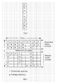
- FIG.2 is schematic diagram illustrating the channel overhead of VC-3/VC-4/VC-4-Xc in an SDH
- FIG.3 is a schematic diagram illustrating the overhead in a frame format of an SDH STM-1 line
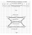
- FIG.4 is a coding format for transporting the discriminators of the individual channels through an HDLC link on the STM-64 port in an SDH network;
- FIG.5 is a schematic diagram illustrating an example of a MESH
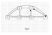
- FIG.6 is a schematic diagram illustrating the two methods for network restoration.
- the term "MESH” used herein refers to a mesh optical network.
- the optical network includes Synchronous Digital Hierarchy (SDH), Synchronous Optical Network (SONET) and Optical Transport Network (OTN).
- SDH Synchronous Digital Hierarchy
- SONET Synchronous Optical Network
- OTN Optical Transport Network
- "Bit-based protocol” refers to a protocol realized by repeatedly transferring a bit-encoded signal sequence through a dedicated communication channel, which has many advantages, for example, the implementation being simple, less software support being required and the transfer time delay being predictable.
- Message-based protocol refers to a protocol realized through a method of transporting message packets, for example, Internet Protocol (IP), which can be used with flexibility, but needs more supporting software, and for which the predictability of the transfer time delay is not good.
- IP Internet Protocol
- Link refers to a fixed connection between two optical network elements generally based on an optical fiber or specific wavelength therein, wherein after being combined through various multiplexing technologies, multiple “channels” are transported through one link, and in the peer optical network element, the combined channels are demultiplexed into the original multiple channels.
- Working path refers to a network connection used for transporting a client signal among different sites
- restoration path refers to a network connection used for restoring the transport of the client signal when the working path fails and preventing the transport of the client signal from being interrupted due to a network failure, wherein to improve the utilization ratio of the network bandwidth, the restoration path can only reserve channel resources, which can be shared among multiple restoration paths.
- both the working path and the restoration path are bidirectional in the optical network, and the establishing process is generally implemented from one end (i.e. "initiating end") to another end (i.e., “terminating end”), thus hereinafter the unidirectional connection identical to the establishing direction of the bidirectional connection is called the "forward direction", while the opposite unidirectional connection is called “reverse direction”.
- “Resource reservation” refers to reserving channel resources and cross connections for the establishment of the network connection in advance so as to prevent the resources being occupied by the establishment of another connection.
- Restoration path activation refers to establishing a cross connection on a predetermined restoration path by utilizing the reserved resources, enabling this path to be used definitely for transporting services.
- Discriminator refers to a value assigned and negotiated for a specific restoration path through a specific link by the upstream and downstream network elements of the link, which is used for indicating, between the upstream and downstream network element, a channel through which the peer can activate the corresponding restoration path, and uniquely determining a restoration path when multiple restoration paths share this reserved channel.
- a discriminator is transported through the associated signaling channel, the coding uniqueness of a discriminator can be on a channel-level or a link-level, and a discriminator can be transported through a bit-based protocol or a message-based protocol.
- Fig.1 is a flow chart illustrating an embodiment of the method for MESH service restoration according to the present invention.
- the MESH restoration method of the present invention includes the steps of:
- a discriminator in the present invention is first used to indicate whether a restoration of the individual channels of a restoration path needs to be performed; and second, used to determine which restoration path the channel resources should be applied to, when the channel resources on a restoration path are shared, i.e. one channel of a link is used for multiple restoration paths.
- the discriminator is related to the shared usage of a channel, and the number of the coded bits concerns with the maximal number of times that the restoration resources are permitted to be shared in a practical network. The greater the number of times is, the higher the utilization ratio of bandwidth is, and the larger a risk of restoration failure due to resource competition upon restoration is; in general, the number of the coded bits is selected from 3 to 10 to achieve a better effect.
- the overhead for transporting the discriminators (which will be explained below) is transferred all along, in a normal status of the network, the discriminators may transfer a specific value (for example, 0) indicating the restoration channels are in an idle status.
- the discriminators may be coded through bit compression coding, each occupying 2-4 bits, and accordingly, each overhead byte can transfer multiple discriminators based on the bit field.
- the overhead occupation can be further compressed through multi-frame coding, e.g., 8-frame coding can compress the required number of the overhead bytes to 1/8, but the time for detecting the overhead will be accordingly prolonged by 8 times.
- a discriminator may also include a code indicating a normal status, i.e. a code indicating that the restoration path needs not to be activated, for example, 0, in which case the discriminator may be referred to as an idle discriminator. That is to say, when a network element receives a code 0 that indicates a normal status and was not just changed from a non-zero code, no operation needs to be performed.
- FIG.2 is a schematic diagram illustrating the channel overhead of VC-3/VC-4/VC-4-Xc in a SDH.
- the channel overhead of Virtual Container-3 (VC-3) /Virtual Container-4 (VC-4) /standard concatenation of Virtual Container-4 (VC-4-Xc) occupies 1 column of totally 9 bytes, wherein, the 5-8th bits of K3 byte are reserved bits in the standard, and these 4 bits can be used for transporting the discriminators.
- N1 byte can also be used for transporting the discriminators. It needs to arrange the values of the discriminators in the overhead bytes of the corresponding channel on the corresponding link at the network element transmitting the discriminators, and the downstream node detects the corresponding values of the overhead to obtain the discriminators and obtain the port (link) and channel identifications from the positions of the overhead.
- Fig.3 shows the overhead in the frame format of the SDH STM-1 line, wherein, the 5 rows by 9 columns in the lower part of the figure represent the overhead of the multiplex section layer, where the "blanks" represent unused overhead.
- all the overhead shown in Fig. 3 are repeated 64 times in succession, i.e. the position of each byte in the figure represents 64 bytes; when being transported in a practical line, these 64 bytes are transmitted in sequence, and then the 64 repetitions of the next overhead byte are transmitted.
- the position of the overhead is generally expressed in (row, column, count of repetitions), for example, (6, 1, 1) means the first repetition of the byte of row 6, column 1, which corresponds to D4 byte.
- (6, 1, 1) means the first repetition of the byte of row 6, column 1, which corresponds to D4 byte.
- overhead position (9, 6, 3) is used, for the remaining overhead, only the position of the first repetition is occupied, and the other overhead positions are not defined.
- a one-to-one correspondence relationship between the positions of the overhead in the server layer overhead and all the channels born by the server layer is created in advance, thus the port and channel identifications can be obtained directly from the positions of the overhead in the frame structure.
- multiplex section overhead (6, 1, 1) of a STM-64 link corresponds to the first channel
- overhead (6, 1, 2) corresponds to the second channel, and so on.
- the transmitting network element needs to employ the corresponding channel numbers of the discriminators to obtain the positions of the overhead according to the above-mentioned correspondence relationship, and set the corresponding overhead values of the corresponding ports as the discriminator values, while the receiving network element monitors the overhead of the server layer and obtains the channel numbers from the overhead positions according to the above-mentioned relationship.
- the overhead bytes are used as dedicated signaling channels to transport the discriminators as mentioned above, the overhead bytes are repeatedly transmitted with a speed of 8000 frames/second in an SDH/SONET, and transport of the discriminators is implemented through setting overhead bytes, thus the discriminators are repeatedly transmitted all along, and the peer network element monitors the change in the overhead values through hardware and reports the change to the control processor by means of interrupt for corresponding processing.
- DCN Data Communication Network
- HDLC High-level Data Link Control
- the signaling channels should be dedicated ones. If the optical network elements cannot support a lot of undefined overhead processing because of the limitation in hardware, transporting the discriminators through the HDLC protocol can save overhead bytes.
- the HDLC protocol belongs to link layer protocols; here only the coding of this protocol is used, rather than the other procedures, so the processing overhead is very little, and the discriminators can be transported rapidly.
- Fig.4 shows a coding format for transporting the channel discriminators through an HDLC link in a STM-64 port, wherein the hexadecimal value 7E is used for identifying the start and the end of the HDLC frame; the length field is used for indicating the byte length of the following discriminator sequence, and if the discriminators adopt 4-bit codes, and 64 channels occupy 32 bytes, the length field is 32; the check code is used for the receiving end to check the integrality of the frame structure.
- the transmitting network element repeatedly transmits the discriminator frame in succession, and when confirming the frame is correct, the receiving network element transmits a acknowledgement frame to the transmitting network element, and on receiving the acknowledgement frame, the transmitting element network may stop transmitting the discriminator frame and for the next time the discriminator value is changed, start the transmission again.
- the acknowledgement frame can be transmitted in combination with the discriminator frame; if it is transmitted alone, the length field is 0, indicating there is no content of the discriminators contained thereafter.
- the discriminators can be transported through any one of the above-mentioned methods, wherein the corresponding transmitting and receiving methods have been described above in detail, and hereinafter, referred to as transporting the discriminators through "associated signaling channels". It needs to be explained that all the associated signaling channels described above are bidirectional, through which the network elements at the both ends of the link can transmit discriminators to the peer.
- a resource reservation is performed first for the working path and the restoration path of the working path.
- the working path and the restoration path can be obtained through a centralized calculation (referring to Wayne D. Grover, "Mesh-based survivable networks-Options and Strategies for Optical, MPLS, SONET, and ATM Networking", p311-313, PRENTICE HALL PTR, ISBN 0-13-494576-X ) or obtained through a distributed protocol (referring to IETF draft, RSVP-TE Extensions in support of End-to-End GMPLS-based Recovery) . All the methods in which the working path and the restoration path can be obtained can be used to implement the present invention.
- Fig.5 shows an example of a MESH, wherein the MESH includes network element A, B, C, D, E, F, G and H, and the connection relationship is denoted by the bold solid lines in the figure, working path 1 passes through network elements A, B and C, and the restoration path thereof passes through A, D, E and C; working path 2 passes through network elements F, G and H, and the restoration path thereof passes through F, D, E and H. All the links and the working paths and the restoration paths of the network connections in this figure are bidirectional.
- the relevant network elements need to create a restoration mapping table for all the restoration paths, which can be configured through network management or implemented through a signaling protocol.
- a signaling protocol is taken as an example to explain the process of creating the restoration mapping table, and the centralized network management configuration method can be regarded as a centralized implementation of this process, which will not be explained separately.
- the signaling process in the reservation stage for restoration path 1 includes the following steps.
- Ingress network element A receives a message for initiating a resource reservation request for restoration path 1 from the network management system, wherein, the information of the message includes:
- Ingress network element A reserves the corresponding resources for restoration path 1, i.e. channel 1 of port 3, and transmits the request message to the next hop D appointed by the source routing;
- network element D reserves resources according to the information presented by the source routing, and transmits the request to the next hop E;
- network element C assigns channel 1 and discriminator value 1 on port 3 for the restoration path, creates a restoration mapping table as shown by Table 2, and transmits the assigned channels of the restoration path and the discriminator values through a response message to network element E in the direction opposite to that of the request message;
- network element E On receiving the response message, network element E obtains the channel and the discriminator value assigned by network element C, assigns channel 1 and discriminator value 1 on port 1 for the restoration path, creates an item of restoration mapping table as shown by the first item of Table 6, and transmits the assigned channels of the restoration path and the discriminator values through a response message to network element D in the direction opposite to that of the request message;
- network element D On receiving the response message, network element D obtains the channel and the discriminator value assigned by network element E, assigns channel 1 and discriminator value 1 on port 1 for the restoration path, creates an item of restoration mapping table as shown by the first item of Table 5, and transmits the assigned channels of the restoration path and the discriminator values through a response message to network element A in the direction opposite to that of the request message;
- network element A On receiving the response message, network element A obtains the channels and the discriminator values assigned by network element D, and creates a restoration mapping table as shown by Table 1, and the signaling processing in the reservation stage for the restoration path is accomplished.
- Table 1 The restoration mapping table of network element A Ingress Port Ingress Channel Ingress Discriminator Value Egress Port Egress Channel Egress Discriminator Value Remark 1 1 - 3 1 1 Restoration path 1 Table 2.
- the restoration mapping table of network element C Ingress Port Ingress Channel Ingress Discriminator Value Egress Port Egress Channel Egress Discriminator Value Remark 3 1 1 2 1 - Restoration path 1 Table 3.
- the restoration mapping table of network element F Ingress Port Ingress Channel Ingress Discriminator Value Egress Port Egress Channel Egress Discriminator Value Remark 1 1 - 2 1 1 Restoration path 2 Table 4.
- the restoration mapping table of network element H Ingress Port Ingress Channel Ingress Discriminator Value Egress Port Egress Channel Egress Discriminator Value Remark 2 1 1 3 1 - Restoration path 2 Table 5.
- the restoration mapping table of network element D Ingress Port Ingress Channel Ingress Discriminator Value Egress Port Egress Channel Egress Discriminator Value Remark 1 1 1 3 1 1 Restoration path 1 2 1 1 3 1 2 Restoration path 2 Table 6.
- the explanations of the contents in the restoration mapping tables are related to the roles of the network elements on the restoration path, which can be classified into ingress network element, intermediate network element and egress network element:
- the ingress network element of the restoration path wherein the ingress port and the ingress channel (optional) refer to the ingress of the network connection, the ingress discriminators are not used, the egress port and the egress channel provide the egress of the restoration channel, and the egress discriminator presents the discriminator value that needs to be transported through the associated signaling channel;
- the intermediate network element of the restoration path wherein the ingress port, the ingress channel and the ingress discriminator value are received through the associated signaling channel, the egress port and the egress channel provide the egress of the restoration path, and the egress discriminator presents the discriminator value that needs to be transported through a dedicated signaling channel;
- the roles of the network elements are different in terms of a specific restoration path; for different restoration paths, a specific network element may play different roles.
- the egress discriminator value of the upstream network element must be equal to the ingress discriminator value of the peer network element (the downstream network element).
- the restoration mapping table created at the shared node when the channel resources on the restoration path are shared will be described.
- the MESH shown in Fig.5 considering that there is no correlation between working path 1 and working path 2 in terms of failure, working path 1 and working path 2 share the resources on link D-E.
- the restoration mapping tables shown by Table 3 and Table 4 are formed at network elements F and network element H
- the restoration mapping tables shown by Table 5 and Table 6 are formed at network element D and network element E, which assign different discriminators for different restoration paths, i.e. for the shared restoration path resources, it needs to assign different discriminator values for different restoration paths.
- the above-mentioned method for creating restoration mapping tables is only schematic, and applicable to the case of binding discriminators with channels.
- the process of creating the restoration mapping tables of the network elements needs to be modified accordingly: in the restoration mapping table of the intermediate network element, the ingress restoration channel, egress restoration port, channel and discriminator are obtained from the ingress restoration port and ingress discriminator value, and in the restoration mapping table of the egress network element, the (ingress) restoration channel, and (egress) port and channel of the working path are obtained from the (ingress) restoration port and discriminator.
- the remark part is not necessary.
- the calculation of the restoration mapping tables can be separated from the configuration implemented at the network elements, wherein the calculation can be a centralized calculation performed by the network management system or planning system, or a distributed calculation performed by means of signaling; while the downloading can be configured station-by-station or performed through signaling. There may be a case of centralized calculation with the configurations downloaded through signaling.
- the associated signaling channels for transporting the discriminators also need to be appointed; the establishment of the associated signaling channels is described in detail above, and the details thereof will not be given here.
- the working path is activated.
- the activation of the working path can be implemented through the signaling protocol of the control plane, for example, the GMPLS extended RSVP-TE protocol.
- the method for activating the working path is well known (referring to J.P. Lang, Y. Rekhter, D. Papadimitriou (Editor), "RSVP-TE Extensions in support of End-to-End GMPLS-based Recovery", Internet Draft, Work in progress, draft -ietf -ccamp -gmpls -recovery -e2e -signaling-01.txt, May 2004 .), thus herein the details thereof will not be given.
- the dedicated signaling channel After activating the working path, in normal conditions (i.e. when the working path normally operates), the dedicated signaling channel transmits an idle discriminator, such as an all-zero code.
- the network elements (including all the network elements acting as an initiating end or terminating end of the restoration path) determine whether the working path is interrupted through alarm monitoring. If the network elements find an alarm and determine the working path is interrupted, the restoration path will be activated. When implementing alarm monitoring, it needs to determine the site and type of an alarm to be monitored by determining the working path is to be restored in terms of segment or of path.
- section restoration it needs to detect the server layer alarm of the working path on all the segments (i.e. links) of the working path.
- SDH/SONET For an SDH/SONET, it needs to monitor the alarm of the multiplex section layer, including Loss of Signaling (LOS), Loss of Frame (LOF), Multiplex Section Alarm Indication Signal (MS-AIS), Multiplex Section Remote Defect Indication (MS-RDI), Multiplex Section Signal Degrade (B2SD) and so on; for an OTN, it needs to detect the alarm such as Signal Fail (SF) and Remote Defect Indication (BRDI). If one of these alarms occurs, it needs to implement a local restoration on the link where the alarm occurs, i.e. select another path between the upstream node and the downstream node of the link to bypass the failed link. Multiple channels for the working path can be restored from the interruption due to a link failure through multiple restoration paths, which need to be activated by driving through the steps described below.
- LOS Loss of Signaling
- LEF Loss of Frame
- AIS Channel/Virtual Path
- B3SD Channel Error threshold-crossing
- RDI Remote Defect Indication
- REI Remote Error Indication
- SF Signal Fail
- SD Signal Degrade
- RAI Remote Alarm Indication
- Fig.6 is a schematic diagram used for explaining the two methods for network restoration.
- the working path of service connection A-F passes through A-B-C-F.
- the path restoration is employed, the restoration path passes through path A-D-E-F without intersecting with the nodes (or the links) of the working path; if the segment restoration is employed, the restoration is not performed in view of the end-to-end path, but in view of the link through which the path passes.
- the working channels on link B-C can be restored through multiple restoration paths: paths B-D-E-C and B-A-D-E-C.
- “Working path of the restoration path” refers to a path for which a restoration can be implemented through the restoration path. That is to say, there is no difference between the restoration paths of a segment and a path.
- the process of activating a restoration path includes the steps of: 1) searching the next network element of the restoration path by the ingress network element of the restoration path, transmitting a discriminator whose value corresponds to a restoration to the next network element through the associated signaling channel, and then establishing a cross connection; 2) searching the still next network element according to the received value of the discriminator if the next network element is an intermediate network element of the restoration path, transmitting the discriminator whose value corresponds to a restoration to the still next network element, and then establishing a cross connection, until the egress network element receives the discriminator whose value corresponds to a restoration, and going to step 3); or going to step 3) directly if the next network element is the egress network element; 3) establishing a cross connection by the egress network element.
- the egress network element preferably transmits an acknowledge discriminator to the network elements one-by-one along the path opposite to
- all the network elements first transmit the discriminators, and then establish cross connections.
- a discriminator whose value indicates the activation needs to be performed by the next network element can be transmitted after the cross-connection has been established.
- the ingress network element When establishing a cross connection, the ingress network element implements a bridge (the signals are simultaneously transmitted to the working path and the restoration path) in the forward direction of the connection (consistent with the direction in the activation), and switches the cross to the restoration path in the reverse direction of the connection; an intermediate network element establishes a bidirectional cross connection; and the process for the egress network element is exactly reverse to that for the ingress network element, it switches the cross to the restoration path in the forward direction of the connection and implements a bridge in the reverse direction.
- a bridge the signals are simultaneously transmitted to the working path and the restoration path in the forward direction of the connection (consistent with the direction in the activation), and switches the cross to the restoration path in the reverse direction of the connection
- an intermediate network element establishes a bidirectional cross connection
- the process for the egress network element is exactly reverse to that for the ingress network element, it switches the cross to the restoration path in the forward direction of the connection and implements a bridge in the reverse direction.
- Network element A finds working path 1 is interrupted through alarm monitoring, and starts the restoration process
- Network element A searches the restoration mapping table of network element A through the ingress port and channel of working path 1 and obtains restoration port 3, channel 1 and the value 1 of the discriminator; starts up the associated signaling channels of port 3, channel 1 to transmits the discriminator (whose value is 1) to peer network element D; since the network connection is bidirectional, it needs to establish a cross connection between ingress port 1, channel 1 and restoration port 1, channel 1 in the forward direction (consistent with the direction in the activation) to implement a bridging of the input signals on the working path and the restoration path; while in the reverse direction, it needs to remove the cross connection of the working path and establish a cross from restoration port 3, channel 1 to ingress port 1, channel 1;
- Intermediate network element D detects the value of the discriminator of network element A transported by the associated signaling channel and finds the discriminator is changed from idle status 0 to 1, then searches the restoration mapping table through the discriminator (referring to Table 5) and obtains the restoration port 3, channel 1 and the value 1 of the egress discriminator, and sets the contents of the restoration overhead of the port according to the value of the discriminator; implements a bidirectional cross connection between ingress port 1, channel 1 and egress port 3, channel 1; and as an initiating network element of the next segment of the restoration path, it transmits a discriminator whose value indicates the restoration path needs to be activated to peer network element E through the associated signaling channel;
- Egress network element C detects the value of the discriminator transported by the associated signaling channel and finds the discriminator is changed from idle status 0 to 1, then searches the restoration mapping table (referring to Table 2) through ingress port 3, channel 1 and discriminator value 1 and obtains the egress port 2 and channel 1, and implements a cross-switching at the egress of the restoration path according to the information, accomplishing the service switching from the working path to the restoration path: in the forward direction, it needs to remove the cross connection of the working path and establish a cross from ingress port 3, channel 1 to egress port 2, channel 1; while in the reverse direction, it needs to add a cross from egress port 2, channel 1 to ingress port 3, channel 1 to implement a bridge;
- Egress network element C transmits the value of the discriminator back to the network elements one-by-one through to ingress network element A in the direction opposite to the restoration path, and ingress network element A confirms that the restoration path is accomplished.
- the restoration of the service from the working path to the restoration path is thus accomplished trough activation of the restoration path implemented by the above-mentioned steps. These steps are implemented only according to the information in the memory, which can guarantee the restoration path is established with a high-speed and the restoration speed similar to that for the ASP protocol of shared multiplex section ring can be achieved.
- the network elements receive the discriminator value and find the value of the discriminator is changed from non-zero to zero, it needs to search an established cross connection to be removed according to the original discriminator value, port and channel information; while the downstream node continues to transmit an idle discriminator value of 0 downstream along the restoration path through to the egress network element. If a corresponding cross connection exists, it also needs to remove the cross connection according to the above method. After removing the cross connections, the individual network elements also need to transmit an idle discriminator value of 0 to the upstream network elements.
- the network connection needs to be switched from the restoration path to the original working path, and the cross connection on the restoration path will be released, and these resources can be used for restoring other networks from a failure.
- the steps for releasing the cross connection on the restoration path include: 1) the ingress network element switching the service from the receiving side to the working path, and transmitting an idle discriminator to an intermediate network element along the restoration path; 2) on receiving the idle discriminator, the intermediate network element searching a channel according to the original discriminator value of the restoration path, and transmits the idle discriminator to the channel; repeating step 2) until the egress network element receives the idle discriminator; 3) the egress network element accomplishing cross connection switching in the forward direction of the bidirectional connection, implementing that both directions of the bidirectional service are switched to the working path, and removing the reverse bridge of the bidirectional connection; 4) the egress network element transferring the idle status overhead in the reverse direction of the restoration path, the intermediate network element removing the cross connections in both directions, and the ingress network element removing the bridge at the transmitting side.
- Working path 1 is restored from a failure, and ingress network element A detects an alarm disappear event, and waits for the timeout of waiting-for-restoration timer;
- step 3 If ingress network element A does not detect any alarm again during the waiting-for-restoration time, the restoration process (step 3) will start; otherwise the process will end, and the ingress network element still waits until no alarm is detected;
- Ingress network element A first switches the reverse direction (in which the network element implements receiving) of the bidirectional connection to the working path, and transmits an idle discriminator to network element D through port 1, channel 1 along the restoration path;
- network element D finds the discriminator value of port 1, channel 1 is changed from 1 to idle status 0, obtains egress port 3, channel 1 through searching the restoration mapping table according to the original discriminator value 1 of the restoration path and sets the discriminator of the channel as an idle status;
- Network element E repeats the actions of network element D, sets the discriminator of egress port 2, channel 1 as an idle status;
- egress network element C On receiving the idle status discriminator, egress network element C accomplishes cross connection switching in the forward direction of the bidirectional connection, implementing that both directions of the bidirectional services are switched to the working path, and removes the reverse bridge of the bidirectional connection;
- Egress network element C transfers the idle status overhead in the opposite direction of the restoration path
- network element E and network element D remove the cross connections of both directions
- network element A removes the bridge in the forward direction of the bidirectional connection.
- the restoration time of the network connection refers to the time from the point that the working path fails to the point that the network connection is restored by the activation of the restoration path, i.e. the interruption time of the network connection.
- the length of the restoration time is related to the following factors:
- alarm monitoring time i.e. the time from the point that the network failure occurs (such as the an optical fiber is cut off) to the point that the alarm monitor finds the failure;
- alarm notification time if the alarm occurs in the middle of the network connection, and the restoration operation needs to be performed at the ingress node of the connection, it may be required that a Notification message should be transferred through a DCN, for example, the GMPLS extended REVP-TE supports transmitting a failure notification to the ingress node and egress node through a Notification message;
- restoration signaling transfer time including transmitting time and line propagation delay: for GMPLS extended REVP-TE signaling protocol, the restoration signaling is transferred through a Path message, and in general, each message contains about 500 bytes; the Path message is instantiated for each channel, wherein the restoration signaling needs only one byte or less;
- cross connection configuration time the network elements need time to configure cross connection after receiving the restoration signaling, and the adjustment operation of the cross connection needs time; in an embodiment of the present invention, a method of forwarding restoration signaling first and then starting up cross connection is used, such that the cross connection operation of each network element on the restoration path can be parallelized.
- the processing time can be saved and the restoration process can be accelerated in terms of Factor 3 and Factor 4. If the GMPLS extended RSVP-TE is over a 576kbits/s DCN composed of overhead bytes D4-12 of an SDH, the time required for transporting the Path messages of the restoration signaling on 64 VC-4 channels of STM-64 is 500*8*64/576000, i.e. about 440 ms.
- the signaling transfer of all the 64 channels will be completed in 125 microseconds theoretically; even if taking into account the detection processing of the network elements, the signaling transfer should be completed in about 1 millisecond; if the above-mentioned DCN is used as a dedicated channel, considering the overhead of HDLC packet header, there are 60 bytes of restoration signaling for the 64 channels, then the transmitting time is 50*8/576000, i.e. about 1 millisecond.
- the processing overhead of the GMPLS extended RSVP-TE protocol is considerably complicated, and the protocol processing time is several milliseconds, while the protocol processing described in an embodiment of the present invention only needs a simple table-lookup process, so the processing time can be neglected, and in contrast, serial processing per channel for the restoration signaling of RSVP-TE will further increase the total overhead.
- IP DCN used by the GMPLS is of a sharing nature
- various Notification messages and link state advertisement by routing protocols that need to be implemented when a failure occurs increases the burdens on the DCN, such that the time of the restoration process based on GMPLS signaling will greatly fluctuate; while transferring the restoration signaling through the dedicated restoration signaling channel as described in an embodiment of the present invention can obviate this problem, realizing stability and predictability of the restoration time.
Landscapes
- Engineering & Computer Science (AREA)
- Computer Networks & Wireless Communication (AREA)
- Signal Processing (AREA)
- Data Exchanges In Wide-Area Networks (AREA)
- Small-Scale Networks (AREA)
Applications Claiming Priority (2)
| Application Number | Priority Date | Filing Date | Title |
|---|---|---|---|
| CNB2004100737870A CN100555922C (zh) | 2004-09-10 | 2004-09-10 | 一种实现网格状光网络业务恢复的方法 |
| PCT/CN2005/001445 WO2006026930A1 (fr) | 2004-09-10 | 2005-09-09 | Procede de restauration d'un service de maillage optique |
Publications (3)
| Publication Number | Publication Date |
|---|---|
| EP1737145A1 true EP1737145A1 (fr) | 2006-12-27 |
| EP1737145A4 EP1737145A4 (fr) | 2007-09-05 |
| EP1737145B1 EP1737145B1 (fr) | 2014-06-18 |
Family
ID=36036080
Family Applications (1)
| Application Number | Title | Priority Date | Filing Date |
|---|---|---|---|
| EP05783726.2A Expired - Lifetime EP1737145B1 (fr) | 2004-09-10 | 2005-09-09 | Procédé de restauration de service pour réseaux maillés optiques |
Country Status (4)
| Country | Link |
|---|---|
| US (1) | US7965938B2 (fr) |
| EP (1) | EP1737145B1 (fr) |
| CN (1) | CN100555922C (fr) |
| WO (1) | WO2006026930A1 (fr) |
Cited By (3)
| Publication number | Priority date | Publication date | Assignee | Title |
|---|---|---|---|---|
| WO2007071189A1 (fr) | 2005-12-22 | 2007-06-28 | Huawei Technologies Co., Ltd. | Procede et dispositif de restauration d'un reseau maille partage |
| WO2008154181A1 (fr) | 2007-06-05 | 2008-12-18 | Cisco Technology, Inc. | Réponse à otuk-bdi pour interfaces otn en vue de restaurer des communications bidirectionnelles |
| EP2911325A1 (fr) * | 2014-02-25 | 2015-08-26 | Alcatel Lucent | Détection de défaillance de GCC rapide |
Families Citing this family (26)
| Publication number | Priority date | Publication date | Assignee | Title |
|---|---|---|---|---|
| CN100555922C (zh) | 2004-09-10 | 2009-10-28 | 华为技术有限公司 | 一种实现网格状光网络业务恢复的方法 |
| CN100452739C (zh) * | 2006-05-30 | 2009-01-14 | 北京邮电大学 | 一种面向网格应用的光并行传输方法 |
| US20100238813A1 (en) | 2006-06-29 | 2010-09-23 | Nortel Networks Limited | Q-in-Q Ethernet rings |
| CN101163030A (zh) * | 2006-10-09 | 2008-04-16 | 华为技术有限公司 | 一种建立区分器映射表的方法 |
| FR2909503B1 (fr) * | 2006-12-04 | 2009-10-09 | Alcatel Sa | Procede d'etablissement d'une connexion bidirectionnelle |
| CA2673206A1 (fr) * | 2006-12-28 | 2008-07-10 | Telefonaktiebolaget Lm Ericsson (Publ) | Systeme de protection |
| US8442030B2 (en) * | 2007-03-01 | 2013-05-14 | Extreme Networks, Inc. | Software control plane for switches and routers |
| CN101399704B (zh) * | 2008-11-05 | 2011-05-11 | 中国移动通信集团江苏有限公司 | 发现未开通上网功能但有需求用户的方法 |
| US20100166420A1 (en) * | 2008-12-22 | 2010-07-01 | Electronics And Telecommunications Research Institute | Apparatus and method for controlling route and resource in packet-optic convergence network |
| JP5267191B2 (ja) * | 2009-02-18 | 2013-08-21 | 富士通株式会社 | 光リングネットワークシステム及び光伝送装置 |
| CN101515827B (zh) * | 2009-03-31 | 2011-12-07 | 中兴通讯股份有限公司 | 一种自动交换光网络业务错联阻错的方法及系统 |
| CN101547382B (zh) * | 2009-05-06 | 2012-01-04 | 烽火通信科技股份有限公司 | 一种格状网中非同源同宿主备业务资源分离的方法 |
| CN102104495B (zh) | 2009-12-18 | 2014-07-09 | 华为技术有限公司 | 共享Mesh保护的实现方法和设备及光网络系统 |
| CN102868544A (zh) * | 2011-07-06 | 2013-01-09 | 中兴通讯股份有限公司 | 一种实现共享网格保护的方法及系统 |
| CN102412994A (zh) * | 2011-11-23 | 2012-04-11 | 福建星网锐捷网络有限公司 | 接收设备、发送设备、线路故障处理方法及系统 |
| US8718039B2 (en) * | 2011-12-22 | 2014-05-06 | Tt Government Solutions, Inc. | Signaling protocol for multi-domain optical networks |
| US8854955B2 (en) | 2012-11-02 | 2014-10-07 | Ciena Corporation | Mesh restoration and bandwidth allocation systems and methods for shared risk connection groups |
| JP6229318B2 (ja) * | 2013-06-05 | 2017-11-15 | 富士通株式会社 | 通信システム、通信制御方法、及び、伝送装置 |
| BR122023005931B1 (pt) * | 2014-10-07 | 2024-01-02 | Sedonasys Systems Ltd | Sistemas para gerenciamento de uma falha e de uma rede de comunicação |
| CN108270648A (zh) * | 2016-12-30 | 2018-07-10 | 中国移动通信集团内蒙古有限公司 | 城域骨干传送网otn组网方法 |
| US10536216B1 (en) * | 2018-07-24 | 2020-01-14 | Ciena Corporation | Service synchronization in retain home path scenarios in a control plane network |
| US11178218B2 (en) * | 2019-01-02 | 2021-11-16 | Citrix Systems, Inc. | Bidirectional communication clusters |
| US10862795B2 (en) * | 2019-01-08 | 2020-12-08 | Fujitsu Limited | Provisioning recovery paths in a mesh network |
| US11283518B2 (en) * | 2019-11-08 | 2022-03-22 | Infinera Corporation | Method and apparatus for a restoration network with dynamic activation of pre-deployed network resources |
| CN113810793A (zh) * | 2020-06-12 | 2021-12-17 | 中兴通讯股份有限公司 | 资源部署方法、设备、管控系统及计算机存储介质 |
| WO2024030135A1 (fr) * | 2022-08-05 | 2024-02-08 | Altiostar Networks, Inc. | Système et procédé de distribution de trafic avec commutateur optique |
Family Cites Families (9)
| Publication number | Priority date | Publication date | Assignee | Title |
|---|---|---|---|---|
| US5986783A (en) * | 1997-02-10 | 1999-11-16 | Optical Networks, Inc. | Method and apparatus for operation, protection, and restoration of heterogeneous optical communication networks |
| KR100537746B1 (ko) * | 2001-01-10 | 2005-12-19 | 학교법인 한국정보통신학원 | 광인터넷에서의 MPλS 보호 및 절체방법 |
| US7103044B1 (en) * | 2001-04-17 | 2006-09-05 | Keller Richard B | Utilizing available SONET overhead bytes for additional signaling channels |
| US6952395B1 (en) * | 2001-06-01 | 2005-10-04 | Calix Networks, Inc. | Optical network restoration |
| US7652983B1 (en) * | 2001-06-25 | 2010-01-26 | At&T Intellectual Property Ii, L.P. | Method for restoration and normalization in a mesh network |
| KR100506206B1 (ko) * | 2002-10-16 | 2005-08-05 | 삼성전자주식회사 | 2-광섬유 링형 광 네트워크 |
| CN1499747A (zh) * | 2002-11-07 | 2004-05-26 | 华为技术有限公司 | 一种实现智能光网络保护和恢复的方法 |
| KR100462408B1 (ko) * | 2002-12-10 | 2004-12-17 | 한국전자통신연구원 | Gmpls를 통한 빠른 재 루트 방법 |
| CN100555922C (zh) | 2004-09-10 | 2009-10-28 | 华为技术有限公司 | 一种实现网格状光网络业务恢复的方法 |
-
2004
- 2004-09-10 CN CNB2004100737870A patent/CN100555922C/zh not_active Expired - Fee Related
-
2005
- 2005-09-09 WO PCT/CN2005/001445 patent/WO2006026930A1/fr not_active Ceased
- 2005-09-09 US US11/568,766 patent/US7965938B2/en active Active
- 2005-09-09 EP EP05783726.2A patent/EP1737145B1/fr not_active Expired - Lifetime
Cited By (7)
| Publication number | Priority date | Publication date | Assignee | Title |
|---|---|---|---|---|
| WO2007071189A1 (fr) | 2005-12-22 | 2007-06-28 | Huawei Technologies Co., Ltd. | Procede et dispositif de restauration d'un reseau maille partage |
| EP1898584A4 (fr) * | 2005-12-22 | 2008-11-26 | Huawei Tech Co Ltd | Procede et dispositif de restauration d'un reseau maille partage |
| US7787362B2 (en) | 2005-12-22 | 2010-08-31 | Huawei Technologies Co., Ltd. | Method and device for recovering a shared mesh network |
| WO2008154181A1 (fr) | 2007-06-05 | 2008-12-18 | Cisco Technology, Inc. | Réponse à otuk-bdi pour interfaces otn en vue de restaurer des communications bidirectionnelles |
| US8666242B2 (en) | 2007-06-05 | 2014-03-04 | Cisco Technology, Inc. | Response to OTUk-BDI for OTN interfaces to restore bidirectional communications |
| EP2911325A1 (fr) * | 2014-02-25 | 2015-08-26 | Alcatel Lucent | Détection de défaillance de GCC rapide |
| WO2015128154A1 (fr) * | 2014-02-25 | 2015-09-03 | Alcatel Lucent | Détection rapide de pannes de gcc |
Also Published As
| Publication number | Publication date |
|---|---|
| EP1737145A4 (fr) | 2007-09-05 |
| US7965938B2 (en) | 2011-06-21 |
| EP1737145B1 (fr) | 2014-06-18 |
| CN100555922C (zh) | 2009-10-28 |
| US20090310960A1 (en) | 2009-12-17 |
| CN1747368A (zh) | 2006-03-15 |
| WO2006026930A1 (fr) | 2006-03-16 |
Similar Documents
| Publication | Publication Date | Title |
|---|---|---|
| EP1737145B1 (fr) | Procédé de restauration de service pour réseaux maillés optiques | |
| US8089864B2 (en) | Network restoration | |
| EP1152631B1 (fr) | Surface de supervision de contrôle des réseaux de routage de longeur d'ondes | |
| US7606886B1 (en) | Method and system for providing operations, administration, and maintenance capabilities in packet over optics networks | |
| US7274869B1 (en) | System and method for providing destination-to-source protection switch setup in optical network topologies | |
| US20040179472A1 (en) | Shared path protection method and system | |
| US8467288B2 (en) | Method of path switching and node apparatus | |
| JP5863565B2 (ja) | 光伝送ノードおよび経路切替方法 | |
| US8965197B2 (en) | Method of switching optical transport network and node device | |
| US20080304407A1 (en) | Efficient Protection Mechanisms For Protecting Multicast Traffic in a Ring Topology Network Utilizing Label Switching Protocols | |
| EP2302836B1 (fr) | Procédé, système et dispositif de récupération de service | |
| EP1735950B1 (fr) | Protection de chemin au niveau ligne dans la couche optique | |
| US8264952B2 (en) | Method and apparatus for providing packet ring protection | |
| EP1198157A1 (fr) | Réseaux de communications de données avec haute performance et fiabilité | |
| CN102356606B (zh) | 数字打包的有效载荷的路径级别保护 | |
| WO2011026442A1 (fr) | Procédé, dispositif de communication optique et système pour le traitement d'informations dans un réseau optique | |
| WO2006063512A1 (fr) | Procede de realisation de l'operation de commutation d'un reseau en anneau a origines et destinations multiples | |
| EP2219328B1 (fr) | Procédé de reroutage conditionnel dans un réseau optique commuté automatique | |
| JP6324179B2 (ja) | 通信装置、光伝送システムおよび光伝送装置 | |
| CN1710993B (zh) | 智能光网络中的业务路径优化方法 | |
| EP1322056A1 (fr) | Méthode et élément de réseau pour éviter les connexions érronées dans un réseau de télécommunications en anneau à protection partagée | |
| US20130121696A1 (en) | Apparatus and method for photonic networks | |
| CN101238660A (zh) | 经由光通信线路发送lcas协议的方法 |
Legal Events
| Date | Code | Title | Description |
|---|---|---|---|
| PUAI | Public reference made under article 153(3) epc to a published international application that has entered the european phase |
Free format text: ORIGINAL CODE: 0009012 |
|
| 17P | Request for examination filed |
Effective date: 20061106 |
|
| AK | Designated contracting states |
Kind code of ref document: A1 Designated state(s): AT BE BG CH CY CZ DE DK EE ES FI FR GB GR HU IE IS IT LI LT LU LV MC NL PL PT RO SE SI SK TR |
|
| A4 | Supplementary search report drawn up and despatched |
Effective date: 20070806 |
|
| DAX | Request for extension of the european patent (deleted) | ||
| 17Q | First examination report despatched |
Effective date: 20110817 |
|
| REG | Reference to a national code |
Ref country code: DE Ref legal event code: R079 Ref document number: 602005043958 Country of ref document: DE Free format text: PREVIOUS MAIN CLASS: H04B0010000000 Ipc: H04J0014020000 |
|
| GRAP | Despatch of communication of intention to grant a patent |
Free format text: ORIGINAL CODE: EPIDOSNIGR1 |
|
| RIC1 | Information provided on ipc code assigned before grant |
Ipc: H04J 14/02 20060101AFI20131121BHEP |
|
| INTG | Intention to grant announced |
Effective date: 20131209 |
|
| GRAS | Grant fee paid |
Free format text: ORIGINAL CODE: EPIDOSNIGR3 |
|
| GRAA | (expected) grant |
Free format text: ORIGINAL CODE: 0009210 |
|
| AK | Designated contracting states |
Kind code of ref document: B1 Designated state(s): AT BE BG CH CY CZ DE DK EE ES FI FR GB GR HU IE IS IT LI LT LU LV MC NL PL PT RO SE SI SK TR |
|
| REG | Reference to a national code |
Ref country code: GB Ref legal event code: FG4D |
|
| REG | Reference to a national code |
Ref country code: CH Ref legal event code: EP |
|
| REG | Reference to a national code |
Ref country code: AT Ref legal event code: REF Ref document number: 673877 Country of ref document: AT Kind code of ref document: T Effective date: 20140715 |
|
| REG | Reference to a national code |
Ref country code: IE Ref legal event code: FG4D |
|
| REG | Reference to a national code |
Ref country code: DE Ref legal event code: R096 Ref document number: 602005043958 Country of ref document: DE Effective date: 20140731 |
|
| PG25 | Lapsed in a contracting state [announced via postgrant information from national office to epo] |
Ref country code: CY Free format text: LAPSE BECAUSE OF FAILURE TO SUBMIT A TRANSLATION OF THE DESCRIPTION OR TO PAY THE FEE WITHIN THE PRESCRIBED TIME-LIMIT Effective date: 20140618 Ref country code: LT Free format text: LAPSE BECAUSE OF FAILURE TO SUBMIT A TRANSLATION OF THE DESCRIPTION OR TO PAY THE FEE WITHIN THE PRESCRIBED TIME-LIMIT Effective date: 20140618 Ref country code: GR Free format text: LAPSE BECAUSE OF FAILURE TO SUBMIT A TRANSLATION OF THE DESCRIPTION OR TO PAY THE FEE WITHIN THE PRESCRIBED TIME-LIMIT Effective date: 20140919 Ref country code: FI Free format text: LAPSE BECAUSE OF FAILURE TO SUBMIT A TRANSLATION OF THE DESCRIPTION OR TO PAY THE FEE WITHIN THE PRESCRIBED TIME-LIMIT Effective date: 20140618 |
|
| REG | Reference to a national code |
Ref country code: NL Ref legal event code: VDEP Effective date: 20140618 |
|
| REG | Reference to a national code |
Ref country code: AT Ref legal event code: MK05 Ref document number: 673877 Country of ref document: AT Kind code of ref document: T Effective date: 20140618 |
|
| REG | Reference to a national code |
Ref country code: LT Ref legal event code: MG4D |
|
| PG25 | Lapsed in a contracting state [announced via postgrant information from national office to epo] |
Ref country code: SE Free format text: LAPSE BECAUSE OF FAILURE TO SUBMIT A TRANSLATION OF THE DESCRIPTION OR TO PAY THE FEE WITHIN THE PRESCRIBED TIME-LIMIT Effective date: 20140618 Ref country code: LV Free format text: LAPSE BECAUSE OF FAILURE TO SUBMIT A TRANSLATION OF THE DESCRIPTION OR TO PAY THE FEE WITHIN THE PRESCRIBED TIME-LIMIT Effective date: 20140618 |
|
| PG25 | Lapsed in a contracting state [announced via postgrant information from national office to epo] |
Ref country code: SK Free format text: LAPSE BECAUSE OF FAILURE TO SUBMIT A TRANSLATION OF THE DESCRIPTION OR TO PAY THE FEE WITHIN THE PRESCRIBED TIME-LIMIT Effective date: 20140618 Ref country code: RO Free format text: LAPSE BECAUSE OF FAILURE TO SUBMIT A TRANSLATION OF THE DESCRIPTION OR TO PAY THE FEE WITHIN THE PRESCRIBED TIME-LIMIT Effective date: 20140618 Ref country code: CZ Free format text: LAPSE BECAUSE OF FAILURE TO SUBMIT A TRANSLATION OF THE DESCRIPTION OR TO PAY THE FEE WITHIN THE PRESCRIBED TIME-LIMIT Effective date: 20140618 Ref country code: PT Free format text: LAPSE BECAUSE OF FAILURE TO SUBMIT A TRANSLATION OF THE DESCRIPTION OR TO PAY THE FEE WITHIN THE PRESCRIBED TIME-LIMIT Effective date: 20141020 Ref country code: EE Free format text: LAPSE BECAUSE OF FAILURE TO SUBMIT A TRANSLATION OF THE DESCRIPTION OR TO PAY THE FEE WITHIN THE PRESCRIBED TIME-LIMIT Effective date: 20140618 Ref country code: ES Free format text: LAPSE BECAUSE OF FAILURE TO SUBMIT A TRANSLATION OF THE DESCRIPTION OR TO PAY THE FEE WITHIN THE PRESCRIBED TIME-LIMIT Effective date: 20140618 |
|
| PG25 | Lapsed in a contracting state [announced via postgrant information from national office to epo] |
Ref country code: PL Free format text: LAPSE BECAUSE OF FAILURE TO SUBMIT A TRANSLATION OF THE DESCRIPTION OR TO PAY THE FEE WITHIN THE PRESCRIBED TIME-LIMIT Effective date: 20140618 Ref country code: IS Free format text: LAPSE BECAUSE OF FAILURE TO SUBMIT A TRANSLATION OF THE DESCRIPTION OR TO PAY THE FEE WITHIN THE PRESCRIBED TIME-LIMIT Effective date: 20141018 Ref country code: NL Free format text: LAPSE BECAUSE OF FAILURE TO SUBMIT A TRANSLATION OF THE DESCRIPTION OR TO PAY THE FEE WITHIN THE PRESCRIBED TIME-LIMIT Effective date: 20140618 Ref country code: AT Free format text: LAPSE BECAUSE OF FAILURE TO SUBMIT A TRANSLATION OF THE DESCRIPTION OR TO PAY THE FEE WITHIN THE PRESCRIBED TIME-LIMIT Effective date: 20140618 |
|
| REG | Reference to a national code |
Ref country code: DE Ref legal event code: R097 Ref document number: 602005043958 Country of ref document: DE |
|
| PLBE | No opposition filed within time limit |
Free format text: ORIGINAL CODE: 0009261 |
|
| STAA | Information on the status of an ep patent application or granted ep patent |
Free format text: STATUS: NO OPPOSITION FILED WITHIN TIME LIMIT |
|
| PG25 | Lapsed in a contracting state [announced via postgrant information from national office to epo] |
Ref country code: DK Free format text: LAPSE BECAUSE OF FAILURE TO SUBMIT A TRANSLATION OF THE DESCRIPTION OR TO PAY THE FEE WITHIN THE PRESCRIBED TIME-LIMIT Effective date: 20140618 Ref country code: MC Free format text: LAPSE BECAUSE OF FAILURE TO SUBMIT A TRANSLATION OF THE DESCRIPTION OR TO PAY THE FEE WITHIN THE PRESCRIBED TIME-LIMIT Effective date: 20140618 Ref country code: IT Free format text: LAPSE BECAUSE OF FAILURE TO SUBMIT A TRANSLATION OF THE DESCRIPTION OR TO PAY THE FEE WITHIN THE PRESCRIBED TIME-LIMIT Effective date: 20140618 Ref country code: LU Free format text: LAPSE BECAUSE OF FAILURE TO SUBMIT A TRANSLATION OF THE DESCRIPTION OR TO PAY THE FEE WITHIN THE PRESCRIBED TIME-LIMIT Effective date: 20140909 |
|
| REG | Reference to a national code |
Ref country code: CH Ref legal event code: PL |
|
| 26N | No opposition filed |
Effective date: 20150319 |
|
| REG | Reference to a national code |
Ref country code: IE Ref legal event code: MM4A |
|
| PG25 | Lapsed in a contracting state [announced via postgrant information from national office to epo] |
Ref country code: SI Free format text: LAPSE BECAUSE OF FAILURE TO SUBMIT A TRANSLATION OF THE DESCRIPTION OR TO PAY THE FEE WITHIN THE PRESCRIBED TIME-LIMIT Effective date: 20140618 Ref country code: CH Free format text: LAPSE BECAUSE OF NON-PAYMENT OF DUE FEES Effective date: 20140930 Ref country code: LI Free format text: LAPSE BECAUSE OF NON-PAYMENT OF DUE FEES Effective date: 20140930 |
|
| PG25 | Lapsed in a contracting state [announced via postgrant information from national office to epo] |
Ref country code: IE Free format text: LAPSE BECAUSE OF NON-PAYMENT OF DUE FEES Effective date: 20140909 |
|
| PG25 | Lapsed in a contracting state [announced via postgrant information from national office to epo] |
Ref country code: BG Free format text: LAPSE BECAUSE OF FAILURE TO SUBMIT A TRANSLATION OF THE DESCRIPTION OR TO PAY THE FEE WITHIN THE PRESCRIBED TIME-LIMIT Effective date: 20140618 |
|
| PG25 | Lapsed in a contracting state [announced via postgrant information from national office to epo] |
Ref country code: BE Free format text: LAPSE BECAUSE OF FAILURE TO SUBMIT A TRANSLATION OF THE DESCRIPTION OR TO PAY THE FEE WITHIN THE PRESCRIBED TIME-LIMIT Effective date: 20140618 Ref country code: HU Free format text: LAPSE BECAUSE OF FAILURE TO SUBMIT A TRANSLATION OF THE DESCRIPTION OR TO PAY THE FEE WITHIN THE PRESCRIBED TIME-LIMIT; INVALID AB INITIO Effective date: 20050909 Ref country code: TR Free format text: LAPSE BECAUSE OF FAILURE TO SUBMIT A TRANSLATION OF THE DESCRIPTION OR TO PAY THE FEE WITHIN THE PRESCRIBED TIME-LIMIT Effective date: 20140618 |
|
| REG | Reference to a national code |
Ref country code: FR Ref legal event code: PLFP Year of fee payment: 12 |
|
| REG | Reference to a national code |
Ref country code: FR Ref legal event code: PLFP Year of fee payment: 13 |
|
| REG | Reference to a national code |
Ref country code: FR Ref legal event code: PLFP Year of fee payment: 14 |
|
| PGFP | Annual fee paid to national office [announced via postgrant information from national office to epo] |
Ref country code: DE Payment date: 20240730 Year of fee payment: 20 |
|
| PGFP | Annual fee paid to national office [announced via postgrant information from national office to epo] |
Ref country code: GB Payment date: 20240801 Year of fee payment: 20 |
|
| PGFP | Annual fee paid to national office [announced via postgrant information from national office to epo] |
Ref country code: FR Payment date: 20240808 Year of fee payment: 20 |
|
| REG | Reference to a national code |
Ref country code: DE Ref legal event code: R071 Ref document number: 602005043958 Country of ref document: DE |
|
| REG | Reference to a national code |
Ref country code: GB Ref legal event code: PE20 Expiry date: 20250908 |