EP1737149A2 - Amplificateur hybride SOA-Raman à multi-bande pour CWDM - Google Patents
Amplificateur hybride SOA-Raman à multi-bande pour CWDM Download PDFInfo
- Publication number
- EP1737149A2 EP1737149A2 EP06115566A EP06115566A EP1737149A2 EP 1737149 A2 EP1737149 A2 EP 1737149A2 EP 06115566 A EP06115566 A EP 06115566A EP 06115566 A EP06115566 A EP 06115566A EP 1737149 A2 EP1737149 A2 EP 1737149A2
- Authority
- EP
- European Patent Office
- Prior art keywords
- raman
- amplifier
- optical
- soa
- pump
- Prior art date
- Legal status (The legal status is an assumption and is not a legal conclusion. Google has not performed a legal analysis and makes no representation as to the accuracy of the status listed.)
- Withdrawn
Links
- 238000001069 Raman spectroscopy Methods 0.000 title claims abstract description 78
- 230000003287 optical effect Effects 0.000 claims abstract description 71
- 239000000835 fiber Substances 0.000 claims abstract description 25
- 239000013307 optical fiber Substances 0.000 claims abstract description 15
- 239000004065 semiconductor Substances 0.000 claims abstract description 12
- 238000000034 method Methods 0.000 claims description 16
- 238000001228 spectrum Methods 0.000 claims description 15
- 230000003321 amplification Effects 0.000 claims description 4
- 230000007423 decrease Effects 0.000 claims description 4
- 238000003199 nucleic acid amplification method Methods 0.000 claims description 4
- 230000001902 propagating effect Effects 0.000 claims description 4
- 238000005086 pumping Methods 0.000 claims description 2
- 230000008878 coupling Effects 0.000 abstract 1
- 238000010168 coupling process Methods 0.000 abstract 1
- 238000005859 coupling reaction Methods 0.000 abstract 1
- 230000005540 biological transmission Effects 0.000 description 11
- 238000005516 engineering process Methods 0.000 description 4
- 239000010432 diamond Substances 0.000 description 3
- 230000010287 polarization Effects 0.000 description 2
- 230000015556 catabolic process Effects 0.000 description 1
- 238000006731 degradation reaction Methods 0.000 description 1
- 230000003993 interaction Effects 0.000 description 1
- 238000012986 modification Methods 0.000 description 1
- 230000004048 modification Effects 0.000 description 1
- 238000009877 rendering Methods 0.000 description 1
- 238000000926 separation method Methods 0.000 description 1
- XLYOFNOQVPJJNP-UHFFFAOYSA-N water Substances O XLYOFNOQVPJJNP-UHFFFAOYSA-N 0.000 description 1
Images

Classifications
-
- H—ELECTRICITY
- H04—ELECTRIC COMMUNICATION TECHNIQUE
- H04B—TRANSMISSION
- H04B10/00—Transmission systems employing electromagnetic waves other than radio-waves, e.g. infrared, visible or ultraviolet light, or employing corpuscular radiation, e.g. quantum communication
- H04B10/29—Repeaters
- H04B10/291—Repeaters in which processing or amplification is carried out without conversion of the main signal from optical form
- H04B10/2912—Repeaters in which processing or amplification is carried out without conversion of the main signal from optical form characterised by the medium used for amplification or processing
- H04B10/2916—Repeaters in which processing or amplification is carried out without conversion of the main signal from optical form characterised by the medium used for amplification or processing using Raman or Brillouin amplifiers
-
- G—PHYSICS
- G02—OPTICS
- G02B—OPTICAL ELEMENTS, SYSTEMS OR APPARATUS
- G02B6/00—Light guides; Structural details of arrangements comprising light guides and other optical elements, e.g. couplings
- G02B6/24—Coupling light guides
- G02B6/42—Coupling light guides with opto-electronic elements
-
- G—PHYSICS
- G02—OPTICS
- G02B—OPTICAL ELEMENTS, SYSTEMS OR APPARATUS
- G02B6/00—Light guides; Structural details of arrangements comprising light guides and other optical elements, e.g. couplings
- G02B6/24—Coupling light guides
- G02B6/26—Optical coupling means
-
- H—ELECTRICITY
- H01—ELECTRIC ELEMENTS
- H01S—DEVICES USING THE PROCESS OF LIGHT AMPLIFICATION BY STIMULATED EMISSION OF RADIATION [LASER] TO AMPLIFY OR GENERATE LIGHT; DEVICES USING STIMULATED EMISSION OF ELECTROMAGNETIC RADIATION IN WAVE RANGES OTHER THAN OPTICAL
- H01S3/00—Lasers, i.e. devices using stimulated emission of electromagnetic radiation in the infrared, visible or ultraviolet wave range
- H01S3/05—Construction or shape of optical resonators; Accommodation of active medium therein; Shape of active medium
- H01S3/06—Construction or shape of active medium
- H01S3/063—Waveguide lasers, i.e. whereby the dimensions of the waveguide are of the order of the light wavelength
- H01S3/067—Fibre lasers
- H01S3/06754—Fibre amplifiers
-
- H—ELECTRICITY
- H01—ELECTRIC ELEMENTS
- H01S—DEVICES USING THE PROCESS OF LIGHT AMPLIFICATION BY STIMULATED EMISSION OF RADIATION [LASER] TO AMPLIFY OR GENERATE LIGHT; DEVICES USING STIMULATED EMISSION OF ELECTROMAGNETIC RADIATION IN WAVE RANGES OTHER THAN OPTICAL
- H01S3/00—Lasers, i.e. devices using stimulated emission of electromagnetic radiation in the infrared, visible or ultraviolet wave range
- H01S3/23—Arrangements of two or more lasers not provided for in groups H01S3/02 - H01S3/22, e.g. tandem arrangements of separate active media
- H01S3/2375—Hybrid lasers
-
- H—ELECTRICITY
- H04—ELECTRIC COMMUNICATION TECHNIQUE
- H04B—TRANSMISSION
- H04B10/00—Transmission systems employing electromagnetic waves other than radio-waves, e.g. infrared, visible or ultraviolet light, or employing corpuscular radiation, e.g. quantum communication
- H04B10/29—Repeaters
- H04B10/291—Repeaters in which processing or amplification is carried out without conversion of the main signal from optical form
- H04B10/2912—Repeaters in which processing or amplification is carried out without conversion of the main signal from optical form characterised by the medium used for amplification or processing
- H04B10/2914—Repeaters in which processing or amplification is carried out without conversion of the main signal from optical form characterised by the medium used for amplification or processing using lumped semiconductor optical amplifiers [SOA]
-
- H—ELECTRICITY
- H04—ELECTRIC COMMUNICATION TECHNIQUE
- H04B—TRANSMISSION
- H04B10/00—Transmission systems employing electromagnetic waves other than radio-waves, e.g. infrared, visible or ultraviolet light, or employing corpuscular radiation, e.g. quantum communication
- H04B10/29—Repeaters
- H04B10/291—Repeaters in which processing or amplification is carried out without conversion of the main signal from optical form
- H04B10/293—Signal power control
- H04B10/294—Signal power control in a multiwavelength system, e.g. gain equalisation
-
- H—ELECTRICITY
- H01—ELECTRIC ELEMENTS
- H01S—DEVICES USING THE PROCESS OF LIGHT AMPLIFICATION BY STIMULATED EMISSION OF RADIATION [LASER] TO AMPLIFY OR GENERATE LIGHT; DEVICES USING STIMULATED EMISSION OF ELECTROMAGNETIC RADIATION IN WAVE RANGES OTHER THAN OPTICAL
- H01S2301/00—Functional characteristics
- H01S2301/04—Gain spectral shaping, flattening
-
- H—ELECTRICITY
- H01—ELECTRIC ELEMENTS
- H01S—DEVICES USING THE PROCESS OF LIGHT AMPLIFICATION BY STIMULATED EMISSION OF RADIATION [LASER] TO AMPLIFY OR GENERATE LIGHT; DEVICES USING STIMULATED EMISSION OF ELECTROMAGNETIC RADIATION IN WAVE RANGES OTHER THAN OPTICAL
- H01S3/00—Lasers, i.e. devices using stimulated emission of electromagnetic radiation in the infrared, visible or ultraviolet wave range
- H01S3/005—Optical devices external to the laser cavity, specially adapted for lasers, e.g. for homogenisation of the beam or for manipulating laser pulses, e.g. pulse shaping
-
- H—ELECTRICITY
- H01—ELECTRIC ELEMENTS
- H01S—DEVICES USING THE PROCESS OF LIGHT AMPLIFICATION BY STIMULATED EMISSION OF RADIATION [LASER] TO AMPLIFY OR GENERATE LIGHT; DEVICES USING STIMULATED EMISSION OF ELECTROMAGNETIC RADIATION IN WAVE RANGES OTHER THAN OPTICAL
- H01S3/00—Lasers, i.e. devices using stimulated emission of electromagnetic radiation in the infrared, visible or ultraviolet wave range
- H01S3/005—Optical devices external to the laser cavity, specially adapted for lasers, e.g. for homogenisation of the beam or for manipulating laser pulses, e.g. pulse shaping
- H01S3/0064—Anti-reflection devices, e.g. optical isolaters
-
- H—ELECTRICITY
- H01—ELECTRIC ELEMENTS
- H01S—DEVICES USING THE PROCESS OF LIGHT AMPLIFICATION BY STIMULATED EMISSION OF RADIATION [LASER] TO AMPLIFY OR GENERATE LIGHT; DEVICES USING STIMULATED EMISSION OF ELECTROMAGNETIC RADIATION IN WAVE RANGES OTHER THAN OPTICAL
- H01S3/00—Lasers, i.e. devices using stimulated emission of electromagnetic radiation in the infrared, visible or ultraviolet wave range
- H01S3/09—Processes or apparatus for excitation, e.g. pumping
- H01S3/091—Processes or apparatus for excitation, e.g. pumping using optical pumping
- H01S3/094—Processes or apparatus for excitation, e.g. pumping using optical pumping by coherent light
- H01S3/094096—Multi-wavelength pumping
-
- H—ELECTRICITY
- H01—ELECTRIC ELEMENTS
- H01S—DEVICES USING THE PROCESS OF LIGHT AMPLIFICATION BY STIMULATED EMISSION OF RADIATION [LASER] TO AMPLIFY OR GENERATE LIGHT; DEVICES USING STIMULATED EMISSION OF ELECTROMAGNETIC RADIATION IN WAVE RANGES OTHER THAN OPTICAL
- H01S3/00—Lasers, i.e. devices using stimulated emission of electromagnetic radiation in the infrared, visible or ultraviolet wave range
- H01S3/23—Arrangements of two or more lasers not provided for in groups H01S3/02 - H01S3/22, e.g. tandem arrangements of separate active media
- H01S3/2383—Parallel arrangements
-
- H—ELECTRICITY
- H01—ELECTRIC ELEMENTS
- H01S—DEVICES USING THE PROCESS OF LIGHT AMPLIFICATION BY STIMULATED EMISSION OF RADIATION [LASER] TO AMPLIFY OR GENERATE LIGHT; DEVICES USING STIMULATED EMISSION OF ELECTROMAGNETIC RADIATION IN WAVE RANGES OTHER THAN OPTICAL
- H01S3/00—Lasers, i.e. devices using stimulated emission of electromagnetic radiation in the infrared, visible or ultraviolet wave range
- H01S3/30—Lasers, i.e. devices using stimulated emission of electromagnetic radiation in the infrared, visible or ultraviolet wave range using scattering effects, e.g. stimulated Brillouin or Raman effects
- H01S3/302—Lasers, i.e. devices using stimulated emission of electromagnetic radiation in the infrared, visible or ultraviolet wave range using scattering effects, e.g. stimulated Brillouin or Raman effects in an optical fibre
-
- H—ELECTRICITY
- H04—ELECTRIC COMMUNICATION TECHNIQUE
- H04B—TRANSMISSION
- H04B2210/00—Indexing scheme relating to optical transmission systems
- H04B2210/25—Distortion or dispersion compensation
- H04B2210/258—Distortion or dispersion compensation treating each wavelength or wavelength band separately
Definitions
- the present invention relates generally to transporting multiple wavelength channels on a single optical fiber over moderate distances and, more particularly, to a multiband hybrid amplifier for use in coarse wavelength division multiplexing transmission systems.
- CWDM Coarse wavelength division multiplexing
- DWDM dense wavelength division multiplexing
- the ITU standard for CWDM defines a maximum of 18 wavelength channels with a channel-to-channel wavelength separation of 20 nm. That large channel spacing permits a 13-nm channel bandwidth, which in turn makes possible the use of inexpensive CWDM optics and directly modulated, un-cooled semiconductor laser transmitters.
- DWDM systems with typical channel spacings of 0.8 or 0.4 nm, require tightly specified and controlled laser transmitters, since the laser wavelength must fall within a small fraction of a nanometer over the entire life of the laser (typically ⁇ 0.1 nm for a system with 0.8-nm channel spacing).
- Their relatively small channel counts make CWDM systems the natural choice for transporting wavelengths at the edge ofthe network, where traffic is not highly aggregated as it is in the network core.
- CWDM is considered an un-amplified technology since the large wavelength spread occupied by all channels in a typical commercial CWDM system (73 nm for a 4-channel system, 153 nm for an 8-channel system) cannot be accommodated by readily available low cost optical amplifiers.
- inexpensive erbium-doped fiber amplifiers have an optical bandwidth of only about 30 nm.
- Being an un-amplified technology limits the reach ofmost commercial CWDM systems to approximately 80 km. That constraint could be overcome with the invention of a low-cost, broadband optical amplifier.
- SOA semiconductor optical amplifiers
- OSNR optical signal-to-noise ration
- Raman amplifiers have been tried in this application.
- a Raman amplifier is based on the nonlinear optical interaction between the optical signal and a high power pump laser.
- the gain medium may be the existing optical fiber or may be a custom highly non-linear fiber.
- a recently disclosed all-Raman amplifier covering the commercially-standard 8 CWDM channel wavelengths exhibited approximately 10 dB lower gain yet required 7 Raman pumps with widely varying pump powers, a total launched power over 1100 mW, and a custom highly nonlinear fiber (HNLF) gain medium.
- HNLF highly nonlinear fiber
- a data transport system includes an optical fiber cable, at least one coarse wavelength division multiplexer (CWDM) for transmitting an optical signal on the fiber within plurality of signal channels in a wavelength range, at least one Raman pump having a pumping wavelength outside any signal channel, coupled to the fiber to amplify the signal, and at least one semiconductor optical amplifier (SOA) having a gain over at least one of the signal channels, connected to the fiber to amplify the signal.
- CWDM coarse wavelength division multiplexer
- SOA semiconductor optical amplifier
- a gain of the at least one Raman pump may increase as a function of wavelength within the wavelength range, and the gain of the at least one SOA may decrease within the wavelength range. The sum of those gains may be more constant over the wavelength range than the individual gains.
- the at least one Raman pump may comprise a plurality of Raman pumps, outputs of which are multiplexed by a pump multiplexer.
- the output of the pump multiplexer may be coupled onto the optical fiber cable via an optical circulator.
- Another embodiment ofthe invention is a hybrid optical amplifier for amplifying an optical signal.
- the optical signal is transmitted on an optical fiber and has a frequency range.
- the amplifier includes at least one Raman pump coupled to the fiber, having a gain within the frequency range and creating a Raman amplified signal.
- the hybrid amplifier further includes a band demultiplexer for splitting the Raman amplified signal propagating in the fiber into a plurality of band signals having band frequency ranges, at least one semiconductor optical amplifier (SOA), each said SOA connected for amplifying a band signal of the plurality of band signals, and having a gain within the band frequency range of the band signal, and a band multiplexer for recombining the band signals after amplification.
- SOA semiconductor optical amplifier
- the at least one Raman pump may comprise three Raman pumps, outputs of which are multiplexed by a pump multiplexer.
- An output of the pump multiplexer may be coupled onto the optical fiber cable via an optical circulator.
- the optical signal may comprise a plurality of wavelength bands, in which case a summed gain of the Raman pumps increases monotonically across each wavelength band.
- the optical signal may include at least two frequency channels having a null frequency range between the channels, and at least one of the Raman pumps in that case may include a pump laser having a frequency within the null frequency range.
- the Raman pumps may include a first pump laser having emission wavelength 1365 nm and optical power coupled into the Raman gain medium 200 mW, a second pump having emission wavelength 1430 nm and optical power coupled into the Raman gain medium 250 mW, and a third pump having emission wavelength 1500 nm and optical power coupled into the Raman gain medium 150 mW.
- the at least one SOA may comprise a plurality of SOAs, one connected for amplifying each band signal.
- the optical signal may comprise at least two frequency bands, wherein the at least one SOA comprises a single SOA amplifying a first of said frequency bands, and a second of said frequency bands is not amplified by an SOA.
- the optical signal may comprise an 8-channel spectrum, and wherein the band demultiplexer may split the spectrum into two 4-channel bands.
- Yet another embodiment of the invention is a method for amplifying a CWDM optical signal having at least first and second frequency bands.
- the method includes the steps of amplifying the CWDM optical signal using at least one Raman pump coupled to the optical fiber cable, splitting the amplified CWDM optical signal into the at least two frequency bands, further amplifying at least one of the frequency bands using a semiconductor optical amplifier (SOA), and recombining the at least two frequency bands.
- SOA semiconductor optical amplifier
- the at least one Raman pump may comprise a plurality of pump lasers, each having a different wavelength.
- the bands of the CWDM optical signal may comprise channels having null frequency ranges between them, in which case a wavelength of at least one of the plurality of pump lasers may be within the null frequency.
- a net gain of the Raman amplifying step and the SOA amplifying step may be flat over the CWDM frequency range to within 5 dB.
- the CWDM optical signal may comprise an 8-channel spectrum split into two 4-channel bands, and each band may be separately amplified by an SOA.
- a wavelength spread occupied by the CWDM optical signal may be approximately 153 nm.
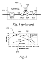
- FIG. 1 is a schematic representation of a prior art hybrid amplifier.
- FIG. 2 is a gain versus wavelength plot representing several components of the amplifier of FIG. 1.
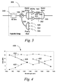
- FIG. 3 is a schematic representation of a hybrid amplifier according to one embodiment of the invention.
- FIG. 4 is a gain versus wavelength plot representing several components of the amplifier of FIG. 3.
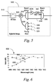
- FIG. 5 is a schematic representation of a hybrid amplifier according to another embodiment of the invention.
- FIG. 6 is a gain versus wavelength plot representing several components of the amplifier of FIG. 5.
- FIG. 7 is a flow chart showing a method according to one embodiment of the invention.
- the presently-described invention is a multi-band hybrid SOA-Raman amplifier capable of amplifying all 8 CWDM channels typically used in today's commercial systems. As described herein, the unique design of this amplifier not only facilitates simultaneous amplification of the 8-channel band, but makes possible relatively long distance transmission via a multi-amplifier cascade.
- the inventors recently measured gain and transmission system bit-error rate performance for a broadband (4 channels from 1510 nm to 1570 nm) hybrid amplifier based on a single SOA and a single Raman pump laser. That amplifier 100, which has been previously demonstrated for DWDM systems, is shown schematically in Fig. 1.
- a backward propagating semiconductor Raman pump laser 120 is coupled to the transmission fiber 110 with a wavelength division multiplexing (WDM) coupler 130, followed by a conventional polarization independent SOA 140 and an optical isolator 150.
- WDM wavelength division multiplexing
- the Raman pump wavelength is chosen to compliment the SOA such that the combined gain of the hybrid amplifier is both increased and flattened as compared to the SOA alone.
- a plot 200 of measured gains of the components of the hybrid amplifier of FIG. 1 is presented in FIG. 2. Specifically, that figure shows the measured gain spectra 230 of the SOA alone (triangles), Raman amplifier 220 alone (diamonds), and the hybrid amplifier 250 (squares).
- the Raman pump laser operated at 1480-nm wavelength with 300-mW coupled into the transmission fiber, and the SOA gain peak was approximately 1510-nm wavelength.
- the transmission fiber which is necessary to provide Raman gain, was 60 km of standard reduced water peak fiber (OFS AllWave® fiber). Similar performance is expected for other common transmission fiber types including standard single-mode fiber.
- the SOA gain 230 decreases monotonically from short wavelength to long wavelength within the 4 channel CWDM band 210.
- the Raman gain 220 has the opposite trend, increasing with increasing wavelength.
- this amplifier arrangement alleviates the power penalty due to cross-gain modulation (saturation) in the SOA.
- the pre-emphasis of the long-wavelength channels by the Raman gain permits positioning of the 4 channel band 210 to the long-wavelength side of the SOA gain peak, where cross-gain modulation is reduced.
- Those three attributes make this amplifier far more promising as a candidate for multi-amplifier cascades.
- the increase in gain and gain flatness helps preserve optical signal-to-noise ratio over a multi-amplifier cascade, and the resistance to cross-gain modulation prevents signal degradation due to crosstalk.
- Raman pump wavelength and SOA gain peak that same arrangement could be implemented to cover any contiguous 4 channel band within the 18-channel CWDM spectrum; however, higher pump power would be required at shorter wavelengths due to increased fiber loss.
- FIG. 3 is a schematic representation of a hybrid two-band amplifier 300.
- Multiple pumps 320, 322, 324, shown in the drawing as P 1 , P 2 and P 3 are multiplexed together in a pump multiplexer 326 and coupled onto the transmission fiber 310 via an optical circulator 330.
- the Raman amplified 8-channel spectrum is split into two 4-channel bands in the band demultiplexer 340, and each band is separately amplified by SOAs (B 1 ) 342 and (B 2 ) 344.
- the SOAs 342, 344 are followed by optical isolators 350, 352, and the amplified bands are recombined in band multiplexer 355.
- the hybrid amplifier 300 of FIG. 3 is shown with three Raman pumps 320, 322, 324, the number of pumps, pump wavelengths and pump powers may vary depending on the desired peak gain and gain shape.
- One exemplary configuration having three Raman pumps is represented in the plot 400 of FIG. 4.
- the curve 420 shows the calculated on-off Raman gain for three pumps 320, 322, 324 with wavelengths 1365 nm, 1430 nm, and 1500 nm, and having pump powers of 200 mW, 250 mW, and 150 mW, respectively.
- the moderate net resulting Raman gain 420 serves the same purpose as the Raman gain in the previously described single-band amplifier: it improves gain, improves optical signal-to-noise ratio (OSNR) and decreases gain tilt across each 4-channel band, while allowing operation in the low-crosstalk region of the SOA spectra.
- the 1500-nm pump although falling within the overall 8-channel band, is situated at the null between the 1490-nm and 1510-nm channels and thus should not result in excessive Rayleigh backscattered pump light impinging on the channel receivers.
- Typical SOA gains for SOAs (B 1 ) 430 (triangles) and (B 2 ) 432 (circles), respectively, are then added to the Raman gain resulting in the overall calculated net gain 450 of the hybrid two-band amplifier (squares).
- the net gain is relatively flat over the 8-channel band, with a peak gain of 21.2 dB at 1530 nm and a minimum gain of 17.7 dB at 1610 nm.
- Raman gain for a single pump wavelength naturally increases with increasing signal wavelength, results in a simpler and less costly Raman implementation for this 2-band hybrid amplifier as compared to an all-Raman design.
- FIG. 5 shows a variation 500 of the two-band hybrid SOA-Raman amplifier which uses only one SOA 542 rather than two.
- the SOA 542 is followed by an optical isolator 550 and is between demultiplexer 540 and multiplexer 555, as in the example of FIG. 3.
- Signals 544 within one of the bands do not pass through an SOA. That simpler design comes at the expense of increased Raman pump powers.
- Three backward propagating pump lasers, P 1 (520) at 1365 nm, P 2 (522) at 1455 nm and P 3 (524) at 1500 nm, have output powers of 300 mW, 320 mW, and 220 mW, respectively.
- the proposed amplifier 500 still employs a dmux-mux pair 540, 555 to split (combine) the 8-channel band before (after) SOA B 1 . That conservative design may not be necessary if SOA B 1 exhibits sufficiently low excess loss and polarization dependant loss (PDL) over the long wavelength half of the spectrum (in which case, the dmux and mux 540, 555 can be omitted).
- PDL polarization dependant loss
- the calculated gain for this amplifier configuration is shown in Fig. 6.
- Diamonds again represent the calculated Raman gain 620.
- the Raman gain increases over the short wavelength 4 channel band (1470 nm, 1490 nm, 1510 nm, and 1530 nm), but remains relatively flat over the long wavelength 4-channel band (1550 nm, 1570 nm, 1590 nm, and 1610 nm).
- the Raman process provides all of the amplification for the long-wavelength sub-band, while the net short wavelength gain 650 (squares) is due to both Raman gain and the gain 630 from SOA B 1 (triangles).
- this design exhibits slightly higher gain variation than the previous two-SOA design.
- the calculated net gain varies between a minimum of 17.4 dB and a maximum of 21.9 dB.
- the invention described herein further contemplates a method 700, shown in FIG. 7, for amplifying a CWDM optical signal having at least first and second frequency bands.
- the wavelength spread occupied by the CWDM optical signal may be approximately 153 nm, the spread of many commercially-available CWDM systems.
- the CWDM optical signal may comprise an 8-channel spectrum split into two 4-channel bands.
- the CWDM optical signal is amplified (step 710) using at least one Raman pump coupled to the optical fiber cable.
- the at least one Raman pump may be a plurality of pump lasers, each having a different wavelength.
- the bands of the CWDM optical signal may comprise channels having null frequency ranges between them, in which case a wavelength of at least one of the plurality of pump lasers may be within that null frequency, to prevent excessive Rayleigh backscattered pump light impinging on the channel receivers.
- the amplified CWDM optical signal is then split (step 720) into frequency bands. At least one of the split frequency bands is further amplified (step 730) using a semiconductor optical amplifier (SOA).
- SOA semiconductor optical amplifier
- the net gain of the Raman amplifying step and the SOA amplifying step is flat over the CWDM frequency range to within 5 dB.
- Each band of the CWDM signal may be separately amplified by an SOA.
- the bands are then recombined (step 740).
- the inventors have proposed several new multi-band hybrid SOA-Raman amplifier designs for CWDM transmission systems. Both implementations are capable of simultaneously amplifying 8 CWDM channels from 1470 -1610 nm. Calculations made by the inventors suggest that those cost effective designs will outperform both all-SOA and all-Raman amplifiers in terms of peak gain, gain shape and crosstalk tolerance, and are therefore well suited to applications that require cascaded amplifiers. Furthermore, the maximum individual pump powers required for each of the two designs (250 mW and 300 mW, respectively) are readily available from commercial semiconductor pump lasers.
Landscapes
- Physics & Mathematics (AREA)
- Electromagnetism (AREA)
- Engineering & Computer Science (AREA)
- Computer Networks & Wireless Communication (AREA)
- Signal Processing (AREA)
- Optics & Photonics (AREA)
- Plasma & Fusion (AREA)
- General Physics & Mathematics (AREA)
- Optical Communication System (AREA)
- Optical Modulation, Optical Deflection, Nonlinear Optics, Optical Demodulation, Optical Logic Elements (AREA)
- Lasers (AREA)
Applications Claiming Priority (2)
| Application Number | Priority Date | Filing Date | Title |
|---|---|---|---|
| US69315805P | 2005-06-23 | 2005-06-23 | |
| US11/260,449 US7446933B2 (en) | 2005-06-23 | 2005-10-27 | Multi-band hybrid SOA-Raman amplifier for CWDM |
Publications (2)
| Publication Number | Publication Date |
|---|---|
| EP1737149A2 true EP1737149A2 (fr) | 2006-12-27 |
| EP1737149A3 EP1737149A3 (fr) | 2007-12-05 |
Family
ID=37011933
Family Applications (1)
| Application Number | Title | Priority Date | Filing Date |
|---|---|---|---|
| EP06115566A Withdrawn EP1737149A3 (fr) | 2005-06-23 | 2006-06-16 | Amplificateur hybride SOA-Raman à multi-bande pour CWDM |
Country Status (5)
| Country | Link |
|---|---|
| US (6) | US7446933B2 (fr) |
| EP (1) | EP1737149A3 (fr) |
| JP (1) | JP2007006500A (fr) |
| KR (1) | KR20060134856A (fr) |
| CA (1) | CA2550633A1 (fr) |
Cited By (1)
| Publication number | Priority date | Publication date | Assignee | Title |
|---|---|---|---|---|
| US7463412B2 (en) * | 2005-06-23 | 2008-12-09 | At&T Corp. | Multi-band hybrid SOA-raman amplifier for CWDM |
Families Citing this family (19)
| Publication number | Priority date | Publication date | Assignee | Title |
|---|---|---|---|---|
| WO2006001229A1 (fr) * | 2004-06-23 | 2006-01-05 | Nippon Telegraph And Telephone Corporation | Système de communication par répéteur linéaire et fibre optique |
| US7643758B1 (en) * | 2006-01-04 | 2010-01-05 | Cisco Technology, Inc. | CWDM system architecture with amplification |
| US7443575B1 (en) * | 2006-04-27 | 2008-10-28 | At&T Corp | Discrete hybrid SOA-Raman amplifier with broad gain bandwidth |
| US7567377B2 (en) * | 2006-02-03 | 2009-07-28 | At&T Corp. | Multiband amplifier based on discrete SOA-Raman amplifiers |
| US20070281626A1 (en) * | 2006-06-05 | 2007-12-06 | Dobosz Paul J | Vehicle telematics satellite data transceiver utilizing fm radio circuitry |
| US8699881B1 (en) | 2006-11-28 | 2014-04-15 | At&T Intellectual Property Ii, L.P. | Method and apparatus for providing passive optical networks with extended reach and/or split |
| US8224183B1 (en) | 2006-11-28 | 2012-07-17 | At&T Intellectual Property Ii, L.P. | Method and apparatus for enabling multiple passive optical networks to share one or more sources |
| US8238751B1 (en) * | 2006-11-28 | 2012-08-07 | At&T Intellectual Property Ii, L.P. | Method and apparatus for enabling multiple optical line termination devices to share a feeder fiber |
| KR100931824B1 (ko) | 2007-12-14 | 2009-12-15 | 충남대학교산학협력단 | 반도체 양자점 집적광소자 |
| JP4973559B2 (ja) * | 2008-03-24 | 2012-07-11 | 富士通株式会社 | 光増幅器および光サージ抑圧方法 |
| JP2010021341A (ja) * | 2008-07-10 | 2010-01-28 | Fujitsu Ltd | 光増幅システムおよび光増幅方法 |
| HU229773B1 (hu) | 2009-09-02 | 2014-06-30 | Eszköz sebészeti beavatkozáshoz | |
| US8761611B2 (en) * | 2010-07-20 | 2014-06-24 | Futurewei Technologies, Inc. | Wavelength assignment for multiple operator support |
| JP5626083B2 (ja) | 2011-04-11 | 2014-11-19 | 富士通株式会社 | 光増幅装置 |
| US8964284B2 (en) * | 2012-04-18 | 2015-02-24 | Infinera Corporation | Banded semiconductor optical amplifier |
| US20170272197A1 (en) * | 2016-03-17 | 2017-09-21 | Telekom Malaysia Berhad | Extender For Optical Access Communication Network |
| CN107275915B (zh) * | 2017-04-27 | 2019-04-16 | 中国科学院国家授时中心 | 一种基于混合型8字腔锁模的掺铒光纤飞秒激光器 |
| US11095388B2 (en) | 2017-09-29 | 2021-08-17 | Nec Corporation | Optical amplification device and light amplification method |
| CN112655122B (zh) * | 2018-08-30 | 2025-04-25 | Ofs菲特尔有限责任公司 | 宽增益带宽c波段光纤放大器 |
Family Cites Families (32)
| Publication number | Priority date | Publication date | Assignee | Title |
|---|---|---|---|---|
| EP2306605B1 (fr) * | 1998-07-23 | 2012-05-23 | The Furukawa Electric Co., Ltd. | Unité de pompage pour un amplificateur Raman et amplificateur Raman comportant la même |
| US6052219A (en) * | 1999-02-16 | 2000-04-18 | Tyco Submarine Systems Ltd. | Wide bandwidth Raman amplifier capable of employing pump energy spectrally overlapping the signal |
| JP3600063B2 (ja) * | 1999-04-30 | 2004-12-08 | 日本電信電話株式会社 | 分布増幅型ファイバラマン増幅器を用いた光ファイバ通信システム |
| JP3573329B2 (ja) * | 1999-05-20 | 2004-10-06 | 日本電信電話株式会社 | 光増幅器及びそれを用いた光ファイバ通信システム |
| US6657778B1 (en) * | 1999-07-30 | 2003-12-02 | Mitsubishi Denkikabushiki Kaisha | Optical amplification repeater and optical amplification repeating and transmitting system |
| JP2001102666A (ja) * | 1999-09-28 | 2001-04-13 | Fujitsu Ltd | 光増幅器 |
| US6307668B1 (en) * | 1999-10-04 | 2001-10-23 | Optigain, Inc. | Ultra-wide bandwidth fiber based optical amplifier |
| US6747793B1 (en) * | 1999-11-15 | 2004-06-08 | Axsun Technologies, Inc. | System with integrated semiconductor optical amplifier array and switching matrix |
| JP4821037B2 (ja) * | 2000-08-25 | 2011-11-24 | 富士通株式会社 | ラマン増幅を用いた光増幅器およびラマン励起光源 |
| JP2002076482A (ja) * | 2000-08-31 | 2002-03-15 | Fujitsu Ltd | 光増幅器,光増幅方法及び光増幅システム |
| US6560010B1 (en) * | 2000-12-14 | 2003-05-06 | Genoa Corporation | Broadband gain-clamped semiconductor optical amplifier devices |
| WO2002067481A1 (fr) * | 2001-02-20 | 2002-08-29 | University Of Maryland, Baltimore County | Systeme optique integre largement accordable et procede associe |
| US20020191277A1 (en) * | 2001-06-14 | 2002-12-19 | Jds Uniphase Corporation | Method and apparatus for amplifying an optical signal |
| KR100395430B1 (ko) * | 2001-10-29 | 2003-08-21 | 이동한 | 라만 광섬유증폭기와 반도체 광증폭기의 결합장치 |
| US20040208566A1 (en) * | 2002-01-09 | 2004-10-21 | Jin Yu | Coarse WDM system of large capacity with un-cooled lasers |
| CA2422206C (fr) * | 2002-03-15 | 2011-06-14 | Tyco Telecommunications (Us) Inc. | Amplificateur hybride raman/a fibre dopee a l'erbium et systeme de transmission a profil de dispersion |
| US7075712B2 (en) * | 2002-05-30 | 2006-07-11 | Fujitsu Limited | Combining and distributing amplifiers for optical network and method |
| JP2004086143A (ja) * | 2002-06-28 | 2004-03-18 | Sumitomo Electric Ind Ltd | 光伝送システム |
| US7149433B2 (en) * | 2002-06-28 | 2006-12-12 | Infineria Corporation | Upgrade of optical amplifier site to a digital optical network site in an optical transmission network |
| EP1566002B1 (fr) * | 2002-11-29 | 2007-02-28 | Pirelli & C. S.p.A. | Systeme de communication optique |
| US7421207B2 (en) * | 2002-12-13 | 2008-09-02 | Pivotal Decisions Llc | Single fiber duplex optical transport |
| JP2004289811A (ja) * | 2003-03-04 | 2004-10-14 | Sumitomo Electric Ind Ltd | 光伝送システム |
| JP4439193B2 (ja) * | 2003-03-20 | 2010-03-24 | 富士通株式会社 | 半導体光増幅器及び光増幅方法 |
| JP4176527B2 (ja) * | 2003-03-31 | 2008-11-05 | 富士通株式会社 | ラマン増幅器およびそれを用いた光伝送システム |
| KR100593999B1 (ko) * | 2003-10-27 | 2006-06-30 | 삼성전자주식회사 | 메트로 파장분할다중 네트웍 |
| US7324268B2 (en) * | 2003-11-21 | 2008-01-29 | Bti Photonic Systems Inc. | Optical signal amplifier and method |
| KR100605927B1 (ko) * | 2004-01-28 | 2006-08-01 | 삼성전자주식회사 | 메트로 파장분할다중 네트웍 |
| US7088498B2 (en) * | 2004-06-29 | 2006-08-08 | Sprint Communications Company L.P. | Optical amplification of CWDM channels using optical amplifiers having fluoride-based optical fiber |
| KR100622015B1 (ko) * | 2004-10-07 | 2006-09-19 | 한국전자통신연구원 | 증폭된 자발방출광(ase) 반사형 이득고정형 광섬유증폭기 |
| KR100592880B1 (ko) * | 2004-12-10 | 2006-06-26 | 한국전자통신연구원 | 병렬 구조 라만 광증폭기 |
| US7446933B2 (en) * | 2005-06-23 | 2008-11-04 | At&T Corp | Multi-band hybrid SOA-Raman amplifier for CWDM |
| US7567377B2 (en) * | 2006-02-03 | 2009-07-28 | At&T Corp. | Multiband amplifier based on discrete SOA-Raman amplifiers |
-
2005
- 2005-10-27 US US11/260,449 patent/US7446933B2/en not_active Expired - Lifetime
-
2006
- 2006-06-16 EP EP06115566A patent/EP1737149A3/fr not_active Withdrawn
- 2006-06-19 CA CA002550633A patent/CA2550633A1/fr not_active Abandoned
- 2006-06-22 KR KR1020060056437A patent/KR20060134856A/ko not_active Withdrawn
- 2006-06-23 JP JP2006173279A patent/JP2007006500A/ja active Pending
- 2006-10-05 US US11/543,650 patent/US7463412B2/en not_active Expired - Lifetime
- 2006-10-05 US US11/543,591 patent/US7342714B2/en not_active Expired - Lifetime
-
2008
- 2008-01-14 US US12/008,752 patent/US7626757B2/en not_active Expired - Lifetime
- 2008-04-21 US US12/148,639 patent/US7746547B2/en active Active
- 2008-12-02 US US12/315,353 patent/US7738164B2/en not_active Expired - Lifetime
Non-Patent Citations (2)
| Title |
|---|
| IANNONE P P ET AL: "Amplified CWDM systems" LEOS 2003. 16TH. ANNUAL MEETING OF THE IEEE LASERS & ELECTRO-OPTICS SOCIETY. TUCSON, AZ, OCT. 27 - 28, 2003, ANNUAL MEETING OF THE IEEE LASERS AND ELECTRO-OPTICS SOCIETY, NEW YORK, NY : IEEE, US, vol. VOL. 1 OF 2, 26 October 2003 (2003-10-26), pages 678-679, XP010674751 ISBN: 0-7803-7888-1 * |
| LANNONE P P ET AL: "200 km CWDM transmission using a hybrid amplifier" OPTICAL FIBER COMMUNICATION CONFERENCE, 2005. TECHNICAL DIGEST. OFC/NFOEC ANAHEIM, CA, USA MARCH 6-11, 2005, PISCATAWAY, NJ, USA,IEEE, 6 March 2005 (2005-03-06), pages 171-173, XP010831876 ISBN: 1-55752-783-0 * |
Cited By (1)
| Publication number | Priority date | Publication date | Assignee | Title |
|---|---|---|---|---|
| US7463412B2 (en) * | 2005-06-23 | 2008-12-09 | At&T Corp. | Multi-band hybrid SOA-raman amplifier for CWDM |
Also Published As
| Publication number | Publication date |
|---|---|
| US20060291037A1 (en) | 2006-12-28 |
| KR20060134856A (ko) | 2006-12-28 |
| JP2007006500A (ja) | 2007-01-11 |
| CA2550633A1 (fr) | 2006-12-23 |
| US20080112044A1 (en) | 2008-05-15 |
| US7463412B2 (en) | 2008-12-09 |
| US20070230960A1 (en) | 2007-10-04 |
| EP1737149A3 (fr) | 2007-12-05 |
| US7446933B2 (en) | 2008-11-04 |
| US20090080893A1 (en) | 2009-03-26 |
| US7626757B2 (en) | 2009-12-01 |
| US20090251768A1 (en) | 2009-10-08 |
| US7746547B2 (en) | 2010-06-29 |
| US20070086079A1 (en) | 2007-04-19 |
| US7738164B2 (en) | 2010-06-15 |
| US7342714B2 (en) | 2008-03-11 |
Similar Documents
| Publication | Publication Date | Title |
|---|---|---|
| US7746547B2 (en) | Multi-band hybrid SOA-Raman amplifier for CWDM | |
| US6259555B1 (en) | Multi-band amplification system for dense wavelength division multiplexing | |
| US5696615A (en) | Wavelength division multiplexed optical communication systems employing uniform gain optical amplifiers | |
| US6807376B2 (en) | Gain equalizer which includes a plurality of optical filters for equalizing the gain of an optical amplifier | |
| US6961522B1 (en) | Automatic raman gain and tilt control for ultra-long-distance dense WDM optical communication system | |
| US8064770B2 (en) | System and method for spectral loading an optical transmission system | |
| US7126747B2 (en) | Hybrid optical amplifier coupling Raman fiber amplifier and semiconductor optical amplifier | |
| JP3771010B2 (ja) | 光増幅のための方法及び該方法を実施するためのシステム | |
| US20020191277A1 (en) | Method and apparatus for amplifying an optical signal | |
| KR100810859B1 (ko) | 엘밴드 광신호의 효율적 광증폭 이득향상 장치 | |
| US7567377B2 (en) | Multiband amplifier based on discrete SOA-Raman amplifiers | |
| US6456428B1 (en) | Optical amplifier | |
| US7324268B2 (en) | Optical signal amplifier and method | |
| US6657777B1 (en) | Interleaved lumped raman amplifier structure based on highly nonlinear fibers for densely spaced WDM channels | |
| US7692850B1 (en) | Lumped-Raman amplification structure for very wideband applications | |
| US6268955B1 (en) | Optical amplifier and wave length division multiplexed light transmission system | |
| US7443575B1 (en) | Discrete hybrid SOA-Raman amplifier with broad gain bandwidth | |
| US6621626B1 (en) | Modular optical amplifier structure for highly dense interleaved WDM systems | |
| US20050162732A1 (en) | Metro wavelength division multiplexing network | |
| Masuda et al. | Ultra-wide-band Raman amplifier using tellurite and silica fibres | |
| US7088498B2 (en) | Optical amplification of CWDM channels using optical amplifiers having fluoride-based optical fiber | |
| US20050089336A1 (en) | Metro wavelength division multiplexing network | |
| US6965712B1 (en) | Low cost amplification in DWDM networks |
Legal Events
| Date | Code | Title | Description |
|---|---|---|---|
| PUAI | Public reference made under article 153(3) epc to a published international application that has entered the european phase |
Free format text: ORIGINAL CODE: 0009012 |
|
| AK | Designated contracting states |
Kind code of ref document: A2 Designated state(s): AT BE BG CH CY CZ DE DK EE ES FI FR GB GR HU IE IS IT LI LT LU LV MC NL PL PT RO SE SI SK TR |
|
| AX | Request for extension of the european patent |
Extension state: AL BA HR MK YU |
|
| PUAL | Search report despatched |
Free format text: ORIGINAL CODE: 0009013 |
|
| AK | Designated contracting states |
Kind code of ref document: A3 Designated state(s): AT BE BG CH CY CZ DE DK EE ES FI FR GB GR HU IE IS IT LI LT LU LV MC NL PL PT RO SE SI SK TR |
|
| AX | Request for extension of the european patent |
Extension state: AL BA HR MK YU |
|
| 17P | Request for examination filed |
Effective date: 20080422 |
|
| AKX | Designation fees paid |
Designated state(s): DE FR GB |
|
| GRAP | Despatch of communication of intention to grant a patent |
Free format text: ORIGINAL CODE: EPIDOSNIGR1 |
|
| STAA | Information on the status of an ep patent application or granted ep patent |
Free format text: STATUS: THE APPLICATION IS DEEMED TO BE WITHDRAWN |
|
| 18D | Application deemed to be withdrawn |
Effective date: 20110405 |