EP1737637B1 - Dispositif pour revetir partiellement par extrusion des elements d'insertion metalliques dans un outil de moulage par injection - Google Patents
Dispositif pour revetir partiellement par extrusion des elements d'insertion metalliques dans un outil de moulage par injection Download PDFInfo
- Publication number
- EP1737637B1 EP1737637B1 EP05716142A EP05716142A EP1737637B1 EP 1737637 B1 EP1737637 B1 EP 1737637B1 EP 05716142 A EP05716142 A EP 05716142A EP 05716142 A EP05716142 A EP 05716142A EP 1737637 B1 EP1737637 B1 EP 1737637B1
- Authority
- EP
- European Patent Office
- Prior art keywords
- sealing elements
- insert
- flexible sealing
- mold
- mould
- Prior art date
- Legal status (The legal status is an assumption and is not a legal conclusion. Google has not performed a legal analysis and makes no representation as to the accuracy of the status listed.)
- Expired - Lifetime
Links
Images



Classifications
-
- B—PERFORMING OPERATIONS; TRANSPORTING
- B29—WORKING OF PLASTICS; WORKING OF SUBSTANCES IN A PLASTIC STATE IN GENERAL
- B29C—SHAPING OR JOINING OF PLASTICS; SHAPING OF MATERIAL IN A PLASTIC STATE, NOT OTHERWISE PROVIDED FOR; AFTER-TREATMENT OF THE SHAPED PRODUCTS, e.g. REPAIRING
- B29C45/00—Injection moulding, i.e. forcing the required volume of moulding material through a nozzle into a closed mould; Apparatus therefor
- B29C45/14—Injection moulding, i.e. forcing the required volume of moulding material through a nozzle into a closed mould; Apparatus therefor incorporating preformed parts or layers, e.g. injection moulding around inserts or for coating articles
- B29C45/14336—Coating a portion of the article, e.g. the edge of the article
- B29C45/14418—Sealing means between mould and article
-
- B—PERFORMING OPERATIONS; TRANSPORTING
- B29—WORKING OF PLASTICS; WORKING OF SUBSTANCES IN A PLASTIC STATE IN GENERAL
- B29C—SHAPING OR JOINING OF PLASTICS; SHAPING OF MATERIAL IN A PLASTIC STATE, NOT OTHERWISE PROVIDED FOR; AFTER-TREATMENT OF THE SHAPED PRODUCTS, e.g. REPAIRING
- B29C45/00—Injection moulding, i.e. forcing the required volume of moulding material through a nozzle into a closed mould; Apparatus therefor
- B29C45/14—Injection moulding, i.e. forcing the required volume of moulding material through a nozzle into a closed mould; Apparatus therefor incorporating preformed parts or layers, e.g. injection moulding around inserts or for coating articles
- B29C2045/1486—Details, accessories and auxiliary operations
- B29C2045/14934—Preventing penetration of injected material between insert and adjacent mould wall
-
- B—PERFORMING OPERATIONS; TRANSPORTING
- B29—WORKING OF PLASTICS; WORKING OF SUBSTANCES IN A PLASTIC STATE IN GENERAL
- B29C—SHAPING OR JOINING OF PLASTICS; SHAPING OF MATERIAL IN A PLASTIC STATE, NOT OTHERWISE PROVIDED FOR; AFTER-TREATMENT OF THE SHAPED PRODUCTS, e.g. REPAIRING
- B29C33/00—Moulds or cores; Details thereof or accessories therefor
- B29C33/0038—Moulds or cores; Details thereof or accessories therefor with sealing means or the like
- B29C33/0044—Moulds or cores; Details thereof or accessories therefor with sealing means or the like for sealing off parts of inserts projecting into the mould cavity
-
- B—PERFORMING OPERATIONS; TRANSPORTING
- B29—WORKING OF PLASTICS; WORKING OF SUBSTANCES IN A PLASTIC STATE IN GENERAL
- B29K—INDEXING SCHEME ASSOCIATED WITH SUBCLASSES B29B, B29C OR B29D, RELATING TO MOULDING MATERIALS OR TO MATERIALS FOR MOULDS, REINFORCEMENTS, FILLERS OR PREFORMED PARTS, e.g. INSERTS
- B29K2705/00—Use of metals, their alloys or their compounds, for preformed parts, e.g. for inserts
Definitions
- the invention relates to a device for partially encapsulating metallic insert with an injection mold, which is formed from at least two tool areas, which are each provided with at least one mold plate whose engravings in the closed state of the injection mold at least one mold-forming cavity in which the insert is molded, and at least one free-end, which receives only the insert form, wherein between each mold-forming cavity and a free-standing a sealing area is present, which is formed by oppositely arranged in the mold plates, flexible sealing elements made of plastic.
- the known devices for encapsulating metal parts in the injection molding technique have, inter alia, the disadvantage that a burr-free encapsulation of an insert due to existing tolerances of the metallic insert and the wear of the metallic sealing edges in the injection mold often can hardly be avoided.
- the object of the invention is to provide a new device for partial encapsulation of metallic inserts, with a largely burr-free encapsulation is possible even with unavoidable tolerances of the metallic insert.
- the flexible sealing elements each project out of the planes formed by the mold plate surfaces. This excess of the flexible sealing elements leads to a squeezing and filling of existing bumps, gaps od. Like., Especially in the cut surfaces of the insert.
- the flexible sealing elements are arranged exchangeably in the mold plates.
- the preferred embodiment of the invention is that the flexible sealing elements are each arranged in a receiving region of an insert component, which is mounted exchangeably in a cavity of the mold plate.
- an injection molding machine is generally designated by the reference numeral 10.
- Fig. 1 can be seen schematically illustrated the injection molding machine 10 with an injection mold 11, wherein additionally a feed hopper 12 for the plastic granules and a screw conveyor 13 are shown, in which the plastic granules is liquefied during transport.
- Fig. 2 only the injection mold 11 is shown, which is formed from the tool halves 14 and 15.
- a plan view of mold plates 16,17 of the tool halves 14 and 15 show the 3 and 4 ,
- the mold plates 16 and 17 have opposite guide pins / guide holes 18 through which on the one hand a fixed assignment of the two mold plates 16 and 17 to each other and on the other hand, the opening and closing without relative displacement is possible.
- Fig. 4 the ejector side is shown.
- tether 19 is used, which is produced by a cutting process, used in the automotive industry.
- the length of the tether 19 is about 155 mm, the thickness of about 3.55 mm and the width of about 12.3 mm.
- the tether 19 is provided with a plastic casing 21.
- a first free end 22 can be seen, in which only a receiving space 23 for an end portion 24 of the tether 19 is present.
- the sealing between the mold-forming cavity 20 and the first free end 22 takes place here only by the prior art via metallic sealing surface regions D, D 'of the opposite mold plates 16, 17 and over a surface region D "of the tether 19.
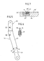
- the mold plate 17, as seen Fig. 4 in conjunction with the sectional view according to section line VIIIc-VIIIc in Fig. 8c shows an insert member 27, in which a flexible sealing element 28 is arranged in a cavity 29.
- the insert member 27 is interchangeable by means of screws 32 arranged in the mold plate 17, but also the flexible sealing element 28 is screwed in a manner not shown in the insert member 27.
- the flexible sealing element 28, the insert component 27 and in part also the mold plate 17 have a contiguous receiving region 30 for the end region 26 of the tether 19, wherein the part of the receiving region 30 which is arranged in the flexible sealing element 28, with respect to the dimensions of the tether 19 a slight undersize.
- the opposite mold plate 16 is provided with a congruent mold-forming cavity 20 ', to which also above an insert member 27' with a flexible sealing element 28 'is connected.
- Fig. 7 - A partial sectional view according to section line VII-VII in Fig. 3 - To recognize the exact arrangement of the mold-forming cavity 20 ', the insert member 27' and the flexible sealing element 28 '.
- a shoulder 31 is arranged between the flexible sealing element 28 'and the mold-forming cavity 20', by which a mechanical support of the flexible sealing element 28 'is to take place during the closure state of the injection mold. Due to this training ultimately results in accordance with the sectional view Fig.
- FIG. 9 In which the sealing zone between the mold-forming cavity 20,20 'and the second free-end 25 is shown.
- the left partial view can be seen in the open position of the tool halves 16 and 17, that the excessively illustrated in section tether 19 has shape and mecanicunregularmontkeiten and has already been pressed into a receiving portion 30 of the flexible sealing element 28 tends to undersize.
- the closed state due to the sealing forces acting on the sealing elements 28, 28 ', the situation arises that the material of the flexible sealing elements 28, 28' projecting beyond the molding plate plane flows into existing free spaces F due to the elastic behavior of the flexible sealing elements 28, 28 '. so that despite irregularities in the shape of the tether 19, a complete seal between the mold-forming cavity 20,20 'and the second Freilicht 25 results.
Landscapes
- Engineering & Computer Science (AREA)
- Manufacturing & Machinery (AREA)
- Mechanical Engineering (AREA)
- Moulds For Moulding Plastics Or The Like (AREA)
- Injection Moulding Of Plastics Or The Like (AREA)
Abstract
Claims (5)
- Dispositif pour revêtir partiellement par extrusion des éléments d'insertion métalliques dans un outil de moulage par injection, qui est formé d'au moins deux zones d'outil dotées respectivement d'au moins un support de matrice dont les gravures, à l'état de fermeture de l'outil de moulage par extrusion, forment au moins une cavité de moulage dans laquelle l'élément d'insertion est revêtu par injection et au moins une position libre qui loge uniquement l'élément d'insertion, une zone d'étanchéité étant présente entre chaque cavité de moulage et une position libre et formée par des éléments d'étanchéité flexibles (28, 28') en plastique disposés en vis-à-vis dans les plaques de moulage (16, 17),
caractérisé en ce que les zones de logement des éléments d'étanchéité (28, 28') pour élément d'insertion (19) présentent une dimension inférieure aux dimensions de l'élément d'insertion (19), les éléments d'étanchéité flexibles (28, 28') étant formés de polymères très performants résistant à la température. - Dispositif selon la revendication 1,
caractérisé en ce que les éléments d'étanchéité flexibles (28, 28') débordent chacun légèrement des plans formés par les surfaces des plaques de moulage. - Dispositif selon la revendication 1,
caractérisé en ce que les éléments d'étanchéité flexibles (28, 28') sont disposés pour être remplaçables. - Dispositif selon la revendication 1, caractérisé en ce que les éléments d'étanchéité flexibles (28, 28') sont disposés respectivement dans une zone de logement (29, 29') d'une pièce d'insertion (27, 27') qui est fixée pour être remplaçable dans une cavité du support de matrice (16,17).
- Dispositif selon la revendication 3,
caractérisé en ce que les pièces d'insertion (27, 27') présentent respectivement un épaulement (31) débordant dans la cavité de moulage (20, 20') dans la région entre la cavité de moulage (20, 20') et les éléments d'étanchéité flexibles (28, 28') pour l'appui de ces derniers.
Priority Applications (1)
| Application Number | Priority Date | Filing Date | Title |
|---|---|---|---|
| PL05716142T PL1737637T3 (pl) | 2004-04-01 | 2005-03-17 | Urządzenie do częściowego obtryskiwania wkładek metalowych pryz użyciu formy wtryskowej |
Applications Claiming Priority (3)
| Application Number | Priority Date | Filing Date | Title |
|---|---|---|---|
| DE202004005370U DE202004005370U1 (de) | 2004-04-01 | 2004-04-01 | Vorrichtung zum teilweisen Umspritzen metallischer Einleger mit einem Spritzgießwerkzeug |
| DE102004016832A DE102004016832B4 (de) | 2004-04-01 | 2004-04-01 | Vorrichtung zum teilweisen Umspritzen metallischer Einleger mit einem Spritzgießwerkzeug |
| PCT/EP2005/002835 WO2005097456A1 (fr) | 2004-04-01 | 2005-03-17 | Dispositif pour revetir partiellement par extrusion des elements d'insertion metalliques dans un outil de moulage par injection |
Publications (2)
| Publication Number | Publication Date |
|---|---|
| EP1737637A1 EP1737637A1 (fr) | 2007-01-03 |
| EP1737637B1 true EP1737637B1 (fr) | 2012-08-08 |
Family
ID=38860774
Family Applications (1)
| Application Number | Title | Priority Date | Filing Date |
|---|---|---|---|
| EP05716142A Expired - Lifetime EP1737637B1 (fr) | 2004-04-01 | 2005-03-17 | Dispositif pour revetir partiellement par extrusion des elements d'insertion metalliques dans un outil de moulage par injection |
Country Status (4)
| Country | Link |
|---|---|
| EP (1) | EP1737637B1 (fr) |
| DE (2) | DE102004016832B4 (fr) |
| PL (1) | PL1737637T3 (fr) |
| WO (1) | WO2005097456A1 (fr) |
Cited By (1)
| Publication number | Priority date | Publication date | Assignee | Title |
|---|---|---|---|---|
| DE102016106568A1 (de) | 2016-04-11 | 2017-10-12 | Dr. Ing. H.C. F. Porsche Aktiengesellschaft | Metallgitter und Verfahren zum Herstellen eines Metallgitters |
Families Citing this family (5)
| Publication number | Priority date | Publication date | Assignee | Title |
|---|---|---|---|---|
| DE102004016832B4 (de) * | 2004-04-01 | 2013-09-19 | Kunststoffinstitut für die mittelständische Wirtschaft NRW GmbH | Vorrichtung zum teilweisen Umspritzen metallischer Einleger mit einem Spritzgießwerkzeug |
| WO2007109329A2 (fr) * | 2006-03-21 | 2007-09-27 | Delphi Technologies, Inc. | Membre structurel intégré destiné à un véhicule et procédé de fabrication |
| FR2934194B1 (fr) * | 2008-07-24 | 2011-03-11 | Plastic Omnium Cie | Procede de fabrication d'un element de vehicule, notamment d'une face avant technique |
| DE102009011731A1 (de) * | 2009-03-09 | 2010-09-16 | Wilo Se | Dichtelement zur Abdichtung elektrischer Kontaktelemente beim Spritzgießen |
| DE102015111893A1 (de) * | 2015-07-22 | 2017-01-26 | Dr. Ing. H.C. F. Porsche Aktiengesellschaft | Spritzgusswerkzeug |
Family Cites Families (12)
| Publication number | Priority date | Publication date | Assignee | Title |
|---|---|---|---|---|
| GB605978A (en) * | 1946-01-07 | 1948-08-04 | Fairey Aviat Co Ltd | Improvements in or relating to insert moulding |
| US4405083A (en) * | 1982-03-19 | 1983-09-20 | Northern Telecom Limited | Moulding apparatus for encapsulating cable splices |
| DE3707196C1 (de) * | 1987-03-06 | 1988-09-29 | United Carr Gmbh Trw | Einschaeumbares Befestigungselement fuer eine geschaeumte Hartschaumverkleidung |
| US4732553A (en) * | 1987-07-06 | 1988-03-22 | Libbey-Owens-Ford Co. | Seal construction for a mold structure for encapsulating glass with a gasket |
| IT1228923B (it) | 1987-08-04 | 1991-07-10 | Vamp Srl | Composizione ritardante di fiamma per polimeri e prodotti polimerici autoestinguenti cosi' ottenuti. |
| US4854599A (en) * | 1987-08-21 | 1989-08-08 | Libbey-Owens-Ford Co. | Seal construction for a mold structure for encapsulating glass with a gasket |
| US4915395A (en) * | 1987-08-21 | 1990-04-10 | Libbey-Owens-Ford Co. | Seal construction for a mold structure for encapsulating glass with a gasket |
| FR2667441B1 (fr) * | 1990-09-27 | 1997-03-28 | Sgs Thomson Microelectronics | Procede de moulage pour boitiers de circuit integre et moule. |
| DE4137805C2 (de) * | 1991-11-16 | 2000-07-06 | Festo Ag & Co | Verfahren zur Herstellung eines Kolbenschiebers sowie Vorrichtung zur Durchführung des Verfahrens |
| US5916600A (en) * | 1996-09-06 | 1999-06-29 | Donnelly Corporation | Mold assembly for holding a sheet of glass during molding |
| JP2000329137A (ja) * | 1999-05-19 | 2000-11-28 | Kanegafuchi Chem Ind Co Ltd | 樹脂ローラ及びその製造方法 |
| DE102004016832B4 (de) * | 2004-04-01 | 2013-09-19 | Kunststoffinstitut für die mittelständische Wirtschaft NRW GmbH | Vorrichtung zum teilweisen Umspritzen metallischer Einleger mit einem Spritzgießwerkzeug |
-
2004
- 2004-04-01 DE DE102004016832A patent/DE102004016832B4/de not_active Expired - Fee Related
- 2004-04-01 DE DE202004005370U patent/DE202004005370U1/de not_active Expired - Lifetime
-
2005
- 2005-03-17 WO PCT/EP2005/002835 patent/WO2005097456A1/fr not_active Ceased
- 2005-03-17 PL PL05716142T patent/PL1737637T3/pl unknown
- 2005-03-17 EP EP05716142A patent/EP1737637B1/fr not_active Expired - Lifetime
Cited By (1)
| Publication number | Priority date | Publication date | Assignee | Title |
|---|---|---|---|---|
| DE102016106568A1 (de) | 2016-04-11 | 2017-10-12 | Dr. Ing. H.C. F. Porsche Aktiengesellschaft | Metallgitter und Verfahren zum Herstellen eines Metallgitters |
Also Published As
| Publication number | Publication date |
|---|---|
| WO2005097456A1 (fr) | 2005-10-20 |
| EP1737637A1 (fr) | 2007-01-03 |
| DE202004005370U1 (de) | 2004-06-09 |
| PL1737637T3 (pl) | 2012-12-31 |
| DE102004016832A1 (de) | 2005-11-03 |
| DE102004016832B4 (de) | 2013-09-19 |
Similar Documents
| Publication | Publication Date | Title |
|---|---|---|
| EP0730936B2 (fr) | Moule pour presse à vibrations | |
| DE102016104019B3 (de) | Vorrichtung zur Herstellung von Gussteilen, wie Aluminiumguss, im Druckgießverfahren oder Niederdruckgießverfahren | |
| DE7234490U (de) | Spritzgussform | |
| DE102007060081A1 (de) | Anordnung aus Trägerteil und Gewindeeinsatz, Verfahren zum Herstellen der Anordnung und Vorrichtung zum Spritzgießen des Gewindeeinsatzes | |
| DE102004016832B4 (de) | Vorrichtung zum teilweisen Umspritzen metallischer Einleger mit einem Spritzgießwerkzeug | |
| EP2628587B1 (fr) | Outil de formage | |
| DE102009031604A1 (de) | Sandgusswerkzeug | |
| DE2937605A1 (de) | Vorrichtung zum umgiessen oder umspritzen der raender von flaechigen bauteilen | |
| EP3075504B2 (fr) | Dispositif de fabrication d'éléments de formage en béton dans une machine à mouler | |
| EP0690956B1 (fr) | Procede de fabrication d'un couvercle coule en metal leger et couvercle ainsi obtenu | |
| EP2134528B1 (fr) | Moule avec cadre, à structure modulaire | |
| DE10343483B4 (de) | Formwerkzeug zum Einformen von Näpfen in eine Packstoffbahn | |
| EP1787784B1 (fr) | Moule pour la fabrication de pièces par moulage par injection, par moulage sous pression ou par un procédé de dépôt | |
| DE102007001756B4 (de) | Verfahren und Spritzgussform zum Spritzgießen von hohlen Formteilen aus Kunststoff | |
| CH621513A5 (fr) | ||
| WO2011095490A2 (fr) | Outil de formage pour fabriquer des pièces moulées par exemple en matière plastique, en particulier dans un matériau composite renforcé par des fibres | |
| DE102007015216B4 (de) | Vorrichtung und Verfahren zur Herstellung eines Hohlkörpers aus mindestens zwei Schichten Kunststoff | |
| EP1517776B1 (fr) | Procede de fabrication d'un papillon dans un corps de papillon continu par moulage par injection de matiere plastique | |
| AT508398A1 (de) | Formwerkzeug | |
| EP1623811B1 (fr) | Moule d'injection pour produire des pièces en matière plastique, en particulier moule d'injection pour produire un angle de connexion entre des profilés en matière plastique | |
| DE10253466C5 (de) | Presswerkzeug für ein Kunststoffbauteil | |
| DE102017215694A1 (de) | SMC-Werkzeug, Verfahren zur Herstellung eines SMC-Bauteils und SMC-Bauteil | |
| DE3906810A1 (de) | Presswerkzeug zur herstellung von formkoerpern, insbesondere blattfedern aus faserverbundwerkstoffen | |
| EP4201631A1 (fr) | Insert de nivellement pour outils de moulage du verre | |
| DE102024111039A1 (de) | Spritzgießwerkzeugplatte und Verwendung eines Halteelements dafür |
Legal Events
| Date | Code | Title | Description |
|---|---|---|---|
| PUAI | Public reference made under article 153(3) epc to a published international application that has entered the european phase |
Free format text: ORIGINAL CODE: 0009012 |
|
| 17P | Request for examination filed |
Effective date: 20060915 |
|
| AK | Designated contracting states |
Kind code of ref document: A1 Designated state(s): AT BE BG CH CY CZ DE DK EE ES FI FR GB GR HU IE IS IT LI LT LU MC NL PL PT RO SE SI SK TR |
|
| RIN1 | Information on inventor provided before grant (corrected) |
Inventor name: FEDLER, MICHAEL, MARIUS |
|
| DAX | Request for extension of the european patent (deleted) | ||
| 17Q | First examination report despatched |
Effective date: 20110519 |
|
| GRAP | Despatch of communication of intention to grant a patent |
Free format text: ORIGINAL CODE: EPIDOSNIGR1 |
|
| RIC1 | Information provided on ipc code assigned before grant |
Ipc: B29K 75/00 20060101ALI20120322BHEP Ipc: B29C 45/14 20060101AFI20120322BHEP |
|
| RTI1 | Title (correction) |
Free format text: DEVICE FOR PARTIALLY EXTRUSION-COATING METALLIC INSERTS IN AN INJECTION MOULD |
|
| GRAS | Grant fee paid |
Free format text: ORIGINAL CODE: EPIDOSNIGR3 |
|
| GRAA | (expected) grant |
Free format text: ORIGINAL CODE: 0009210 |
|
| AK | Designated contracting states |
Kind code of ref document: B1 Designated state(s): AT BE BG CH CY CZ DE DK EE ES FI FR GB GR HU IE IS IT LI LT LU MC NL PL PT RO SE SI SK TR |
|
| REG | Reference to a national code |
Ref country code: GB Ref legal event code: FG4D Free format text: NOT ENGLISH |
|
| REG | Reference to a national code |
Ref country code: AT Ref legal event code: REF Ref document number: 569501 Country of ref document: AT Kind code of ref document: T Effective date: 20120815 Ref country code: CH Ref legal event code: EP |
|
| REG | Reference to a national code |
Ref country code: IE Ref legal event code: FG4D Free format text: LANGUAGE OF EP DOCUMENT: GERMAN |
|
| REG | Reference to a national code |
Ref country code: DE Ref legal event code: R096 Ref document number: 502005012985 Country of ref document: DE Effective date: 20121011 |
|
| REG | Reference to a national code |
Ref country code: NL Ref legal event code: VDEP Effective date: 20120808 |
|
| REG | Reference to a national code |
Ref country code: PL Ref legal event code: T3 |
|
| REG | Reference to a national code |
Ref country code: LT Ref legal event code: MG4D Effective date: 20120808 |
|
| PG25 | Lapsed in a contracting state [announced via postgrant information from national office to epo] |
Ref country code: IS Free format text: LAPSE BECAUSE OF FAILURE TO SUBMIT A TRANSLATION OF THE DESCRIPTION OR TO PAY THE FEE WITHIN THE PRESCRIBED TIME-LIMIT Effective date: 20121208 Ref country code: CY Free format text: LAPSE BECAUSE OF FAILURE TO SUBMIT A TRANSLATION OF THE DESCRIPTION OR TO PAY THE FEE WITHIN THE PRESCRIBED TIME-LIMIT Effective date: 20120808 Ref country code: LT Free format text: LAPSE BECAUSE OF FAILURE TO SUBMIT A TRANSLATION OF THE DESCRIPTION OR TO PAY THE FEE WITHIN THE PRESCRIBED TIME-LIMIT Effective date: 20120808 Ref country code: FI Free format text: LAPSE BECAUSE OF FAILURE TO SUBMIT A TRANSLATION OF THE DESCRIPTION OR TO PAY THE FEE WITHIN THE PRESCRIBED TIME-LIMIT Effective date: 20120808 |
|
| PG25 | Lapsed in a contracting state [announced via postgrant information from national office to epo] |
Ref country code: GR Free format text: LAPSE BECAUSE OF FAILURE TO SUBMIT A TRANSLATION OF THE DESCRIPTION OR TO PAY THE FEE WITHIN THE PRESCRIBED TIME-LIMIT Effective date: 20121109 Ref country code: SE Free format text: LAPSE BECAUSE OF FAILURE TO SUBMIT A TRANSLATION OF THE DESCRIPTION OR TO PAY THE FEE WITHIN THE PRESCRIBED TIME-LIMIT Effective date: 20120808 Ref country code: SI Free format text: LAPSE BECAUSE OF FAILURE TO SUBMIT A TRANSLATION OF THE DESCRIPTION OR TO PAY THE FEE WITHIN THE PRESCRIBED TIME-LIMIT Effective date: 20120808 Ref country code: PT Free format text: LAPSE BECAUSE OF FAILURE TO SUBMIT A TRANSLATION OF THE DESCRIPTION OR TO PAY THE FEE WITHIN THE PRESCRIBED TIME-LIMIT Effective date: 20121210 |
|
| PG25 | Lapsed in a contracting state [announced via postgrant information from national office to epo] |
Ref country code: NL Free format text: LAPSE BECAUSE OF FAILURE TO SUBMIT A TRANSLATION OF THE DESCRIPTION OR TO PAY THE FEE WITHIN THE PRESCRIBED TIME-LIMIT Effective date: 20120808 |
|
| PG25 | Lapsed in a contracting state [announced via postgrant information from national office to epo] |
Ref country code: DK Free format text: LAPSE BECAUSE OF FAILURE TO SUBMIT A TRANSLATION OF THE DESCRIPTION OR TO PAY THE FEE WITHIN THE PRESCRIBED TIME-LIMIT Effective date: 20120808 Ref country code: RO Free format text: LAPSE BECAUSE OF FAILURE TO SUBMIT A TRANSLATION OF THE DESCRIPTION OR TO PAY THE FEE WITHIN THE PRESCRIBED TIME-LIMIT Effective date: 20120808 Ref country code: ES Free format text: LAPSE BECAUSE OF FAILURE TO SUBMIT A TRANSLATION OF THE DESCRIPTION OR TO PAY THE FEE WITHIN THE PRESCRIBED TIME-LIMIT Effective date: 20121119 Ref country code: CZ Free format text: LAPSE BECAUSE OF FAILURE TO SUBMIT A TRANSLATION OF THE DESCRIPTION OR TO PAY THE FEE WITHIN THE PRESCRIBED TIME-LIMIT Effective date: 20120808 Ref country code: EE Free format text: LAPSE BECAUSE OF FAILURE TO SUBMIT A TRANSLATION OF THE DESCRIPTION OR TO PAY THE FEE WITHIN THE PRESCRIBED TIME-LIMIT Effective date: 20120808 |
|
| PG25 | Lapsed in a contracting state [announced via postgrant information from national office to epo] |
Ref country code: SK Free format text: LAPSE BECAUSE OF FAILURE TO SUBMIT A TRANSLATION OF THE DESCRIPTION OR TO PAY THE FEE WITHIN THE PRESCRIBED TIME-LIMIT Effective date: 20120808 |
|
| PLBE | No opposition filed within time limit |
Free format text: ORIGINAL CODE: 0009261 |
|
| STAA | Information on the status of an ep patent application or granted ep patent |
Free format text: STATUS: NO OPPOSITION FILED WITHIN TIME LIMIT |
|
| 26N | No opposition filed |
Effective date: 20130510 |
|
| PG25 | Lapsed in a contracting state [announced via postgrant information from national office to epo] |
Ref country code: BG Free format text: LAPSE BECAUSE OF FAILURE TO SUBMIT A TRANSLATION OF THE DESCRIPTION OR TO PAY THE FEE WITHIN THE PRESCRIBED TIME-LIMIT Effective date: 20121108 |
|
| REG | Reference to a national code |
Ref country code: DE Ref legal event code: R097 Ref document number: 502005012985 Country of ref document: DE Effective date: 20130510 |
|
| BERE | Be: lapsed |
Owner name: MURTFELDT KUNSTSTOFFE G.M.B.H. & CO. KG Effective date: 20130331 |
|
| PG25 | Lapsed in a contracting state [announced via postgrant information from national office to epo] |
Ref country code: MC Free format text: LAPSE BECAUSE OF NON-PAYMENT OF DUE FEES Effective date: 20130331 |
|
| REG | Reference to a national code |
Ref country code: CH Ref legal event code: PL |
|
| GBPC | Gb: european patent ceased through non-payment of renewal fee |
Effective date: 20130317 |
|
| REG | Reference to a national code |
Ref country code: IE Ref legal event code: MM4A |
|
| PG25 | Lapsed in a contracting state [announced via postgrant information from national office to epo] |
Ref country code: CH Free format text: LAPSE BECAUSE OF NON-PAYMENT OF DUE FEES Effective date: 20130331 Ref country code: BE Free format text: LAPSE BECAUSE OF NON-PAYMENT OF DUE FEES Effective date: 20130331 Ref country code: GB Free format text: LAPSE BECAUSE OF NON-PAYMENT OF DUE FEES Effective date: 20130317 Ref country code: IE Free format text: LAPSE BECAUSE OF NON-PAYMENT OF DUE FEES Effective date: 20130317 Ref country code: LI Free format text: LAPSE BECAUSE OF NON-PAYMENT OF DUE FEES Effective date: 20130331 |
|
| PG25 | Lapsed in a contracting state [announced via postgrant information from national office to epo] |
Ref country code: TR Free format text: LAPSE BECAUSE OF FAILURE TO SUBMIT A TRANSLATION OF THE DESCRIPTION OR TO PAY THE FEE WITHIN THE PRESCRIBED TIME-LIMIT Effective date: 20120808 |
|
| PG25 | Lapsed in a contracting state [announced via postgrant information from national office to epo] |
Ref country code: LU Free format text: LAPSE BECAUSE OF NON-PAYMENT OF DUE FEES Effective date: 20130317 Ref country code: HU Free format text: LAPSE BECAUSE OF FAILURE TO SUBMIT A TRANSLATION OF THE DESCRIPTION OR TO PAY THE FEE WITHIN THE PRESCRIBED TIME-LIMIT; INVALID AB INITIO Effective date: 20050317 |
|
| REG | Reference to a national code |
Ref country code: FR Ref legal event code: PLFP Year of fee payment: 12 |
|
| REG | Reference to a national code |
Ref country code: FR Ref legal event code: PLFP Year of fee payment: 13 |
|
| REG | Reference to a national code |
Ref country code: FR Ref legal event code: PLFP Year of fee payment: 14 |
|
| PGFP | Annual fee paid to national office [announced via postgrant information from national office to epo] |
Ref country code: PL Payment date: 20190308 Year of fee payment: 15 Ref country code: FR Payment date: 20190326 Year of fee payment: 15 Ref country code: IT Payment date: 20190321 Year of fee payment: 15 |
|
| PGFP | Annual fee paid to national office [announced via postgrant information from national office to epo] |
Ref country code: AT Payment date: 20190319 Year of fee payment: 15 |
|
| REG | Reference to a national code |
Ref country code: AT Ref legal event code: MM01 Ref document number: 569501 Country of ref document: AT Kind code of ref document: T Effective date: 20200317 |
|
| PG25 | Lapsed in a contracting state [announced via postgrant information from national office to epo] |
Ref country code: AT Free format text: LAPSE BECAUSE OF NON-PAYMENT OF DUE FEES Effective date: 20200317 Ref country code: FR Free format text: LAPSE BECAUSE OF NON-PAYMENT OF DUE FEES Effective date: 20200331 |
|
| PG25 | Lapsed in a contracting state [announced via postgrant information from national office to epo] |
Ref country code: IT Free format text: LAPSE BECAUSE OF NON-PAYMENT OF DUE FEES Effective date: 20200317 |
|
| PG25 | Lapsed in a contracting state [announced via postgrant information from national office to epo] |
Ref country code: PL Free format text: LAPSE BECAUSE OF NON-PAYMENT OF DUE FEES Effective date: 20200317 |
|
| P01 | Opt-out of the competence of the unified patent court (upc) registered |
Effective date: 20230718 |
|
| PGFP | Annual fee paid to national office [announced via postgrant information from national office to epo] |
Ref country code: DE Payment date: 20231215 Year of fee payment: 20 |
|
| REG | Reference to a national code |
Ref country code: DE Ref legal event code: R071 Ref document number: 502005012985 Country of ref document: DE |