EP1737702B9 - System zum abkoppeln eines steuerpedals von der vorrichtung, mit der es verbunden ist - Google Patents
System zum abkoppeln eines steuerpedals von der vorrichtung, mit der es verbunden ist Download PDFInfo
- Publication number
- EP1737702B9 EP1737702B9 EP05730881A EP05730881A EP1737702B9 EP 1737702 B9 EP1737702 B9 EP 1737702B9 EP 05730881 A EP05730881 A EP 05730881A EP 05730881 A EP05730881 A EP 05730881A EP 1737702 B9 EP1737702 B9 EP 1737702B9
- Authority
- EP
- European Patent Office
- Prior art keywords
- rotable
- rotable body
- rod
- pedal
- axis
- Prior art date
- Legal status (The legal status is an assumption and is not a legal conclusion. Google has not performed a legal analysis and makes no representation as to the accuracy of the status listed.)
- Expired - Lifetime
Links
Images


Classifications
-
- B—PERFORMING OPERATIONS; TRANSPORTING
- B60—VEHICLES IN GENERAL
- B60R—VEHICLES, VEHICLE FITTINGS, OR VEHICLE PARTS, NOT OTHERWISE PROVIDED FOR
- B60R21/00—Arrangements or fittings on vehicles for protecting or preventing injuries to occupants or pedestrians in case of accidents or other traffic risks
- B60R21/02—Occupant safety arrangements or fittings, e.g. crash pads
- B60R21/09—Control elements or operating handles movable from an operative to an out-of-the way position, e.g. pedals, switch knobs, window cranks
-
- B—PERFORMING OPERATIONS; TRANSPORTING
- B60—VEHICLES IN GENERAL
- B60T—VEHICLE BRAKE CONTROL SYSTEMS OR PARTS THEREOF; BRAKE CONTROL SYSTEMS OR PARTS THEREOF, IN GENERAL; ARRANGEMENT OF BRAKING ELEMENTS ON VEHICLES IN GENERAL; PORTABLE DEVICES FOR PREVENTING UNWANTED MOVEMENT OF VEHICLES; VEHICLE MODIFICATIONS TO FACILITATE COOLING OF BRAKES
- B60T7/00—Brake-action initiating means
- B60T7/02—Brake-action initiating means for personal initiation
- B60T7/04—Brake-action initiating means for personal initiation foot actuated
- B60T7/06—Disposition of pedal
- B60T7/065—Disposition of pedal with means to prevent injuries in case of collision
-
- Y—GENERAL TAGGING OF NEW TECHNOLOGICAL DEVELOPMENTS; GENERAL TAGGING OF CROSS-SECTIONAL TECHNOLOGIES SPANNING OVER SEVERAL SECTIONS OF THE IPC; TECHNICAL SUBJECTS COVERED BY FORMER USPC CROSS-REFERENCE ART COLLECTIONS [XRACs] AND DIGESTS
- Y10—TECHNICAL SUBJECTS COVERED BY FORMER USPC
- Y10T—TECHNICAL SUBJECTS COVERED BY FORMER US CLASSIFICATION
- Y10T74/00—Machine element or mechanism
- Y10T74/20—Control lever and linkage systems
- Y10T74/20528—Foot operated
Definitions
- the invention relates to a system to disconnect a device control pedal from the device to which it is connected, particularly applicable to pedals such as the pedal of a vehicle brake device.
- EP1134128 and EP1344691 disclose respective devices which enable a vehicle pedal to be disconnected from the device to which said pedal is connected, if the vehicle crashes. With said devices the pedals move away in the opposite direction to that of the driver's position, protecting him/her from the damage the pedals may cause him/her if part of the vehicle structure is distorted and displaces the pedals in the driver's direction.
- the pedal is connected to the device by a rod whose end is connected to a rotable body coupled to the pedal and rotatable around an axis. If a crash occurs and distorts part of the vehicle structure, said rotable body, which is directly connected to the vehicle structure by a side arm joined to the body, is forced to rotate causing the breakage of the end of the rod in the device of document EP 1134128 ; and in the breakage or the separation of the coupling means of the device of document EP 1344691 , provided on the rotable body and responsible for keeping the rod and the rotable body joined together in normal conditions.
- the system to disconnect a device control pedal from the device to which it is connected is particularly applicable to vehicle pedals intended to receive the action of the foot and to transmit the force thereof to the device.
- the pedal is connected to the device by a rod whose end is attached to a first rotable body coupled to the pedal and rotatable around an axis.
- the system is characterized in that it further comprises a second rotable body provided with a pusher element, so that when the second rotable body rotates due to a head-on collision of the vehicle, the rod is displaced due to the action of the pusher element so that it is separated from the first rotable body coupled to the pedal.
- the spin axis of the second rotable body is coincident with the spin axis of the first rotable body coupled to the pedal.
- a portion of the end of the rod attached to the first rotable body is housed in a groove which an end of the first rotable body is provided with, and the system further comprises retention means intended to maintain the rod in said groove.
- the second rotable body comprises an essentially flat portion provided with a through-hole which is traversed by said end of the first rotable body, and the pusher element of the second rotable body is formed by a curved wall, the height of its upper edge being variable and adapted to displace, by way of a cam, the rod attached to the first rotable body when the second rotable body rotates around its axis.
- the retention means are comprised of a tubular body, coaxial to the first rotable body and arranged externally with respect thereto, the tubular body being provided with a prolongation, essentially parallel to its axis, which can be plastically deformed until it is broken when subjected to strain greater than a certain value, which extends through the through-hole of the essentially flat portion of the second rotable body and which is adapted to clasp the rod, preventing it from coming out of the groove of the end of the first rotable body wherein it is housed.
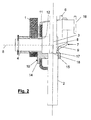
- the example system represented in Fig. 1 comprises a pedal 1 which is adapted to control a device (not shown) using a rod 2, one of the whose ends is connected to said device, whilst its opposite end 3 is connected to the pedal 1, so that when the pedal 1 receives the action of a driver's foot, and displaces it, the force applied to the pedal is transmitted via the rod 2 to said device.
- the rod 2 is connected to the pedal 1 by a first rotable body 4, coupled to the pedal and rotatable around an axis 5.
- the end 3 of the rod is tightly housed in a groove 8 which the end 9 of the first rotable body is provided with.
- the rotatable nature of the first rotable body 4 permits adapting the connection of the rod 2, whose inclination is constant in normal conditions of use, to the different positions which the pedal may adopt according to its degree of actuation by the driver.
- the pedal swings around a spin axis (not shown), when it receives the action of the driver's foot, the rod 2 does not vary its inclination even when being pushed by the pedal, transmitting the force to the device whereto the pedal is connected, e.g. a brake device.
- the system further comprises a second rotable body 6, which can rotate around the same axis 5 as the first rotable body.
- this second rotable body 6 is formed by a plate which comprises an essentially flat portion 11, sandwiched, and rotatable as has been explained above, between the pedal 1 and the rod 2 in its coupling position to the first rotable body 4.
- a through-hole 12 in the flat portion 11 of the plate permits the end 9 of the first rotable body 4 to traverse the plate, thus permitting the coupling of the end 3 of the rod 2.
- the flat portion 11 of said second rotable body 6 is further provided with a pusher element 7, formed by a curved wall 13, the height of the upper edge whereof increasing depending on the rotation direction of the second rotable body 6, so that, if the second rotable body rotates, the upper edge of the curved wall acts by way of a cam on the end 3 of the rod 2, displacing it from the groove 8 of the end 9 of the first rotable body.
- the second rotable body 6 is provided with a piston pin 16, which is pushed when a collision or crash occurs, causing it to rotate around the axis 5 of the second rotable body 6 in the direction indicated by the arrow of Fig. 1 .
- the upper edge of the wall 13 pushes the end 3 of the rod out of the groove 8 which houses it, disconnecting the pedal 1 from the device.
- the force exerted on the rod 2 is essentially normal for the flat portion 11 of the plate of the second rotable body or, in other words, normal for the body of the pedal 1, in addition to it being a second rotable body 6, other than that which supports or connects the rod 2 to the pedal 1, which causes both to disconnect or uncouple.
- the system comprises retention means 10, formed by a tubular body 14 arranged on the outer surface of the first rotable body 4.
- the tubular body 14 is provided with a prolongation 15, parallel to the spin axis 5, which extends through the through-hole 12 of the flat portion 11 of the second rotable body.
- the prolongation 15 is adapted to retain the end 3 of the rod 2 in the groove 8 which houses it. To do this, the prolongation 15 is provided with a through-hole which is traversed by the rod 2.
- the inner wall of the prolongation 15 through-hole is provided with a recess or step 17, intended to receive the support of a projection of the rod 2.
- the end 3 of the rod 2 has a smaller diameter than the main portion of said rod, which produces a step 18 on its outer surface, which acts as a projection and rests on said step 17.
Landscapes
- Engineering & Computer Science (AREA)
- Mechanical Engineering (AREA)
- Transportation (AREA)
- Mechanical Control Devices (AREA)
- Braking Elements And Transmission Devices (AREA)
- Arrangement And Mounting Of Devices That Control Transmission Of Motive Force (AREA)
- Mechanical Operated Clutches (AREA)
- Selective Calling Equipment (AREA)
- Auxiliary Drives, Propulsion Controls, And Safety Devices (AREA)
Claims (5)
- System zum Lösen eines Vorrichtungssteuerungspedals (1) von der Vorrichtung, mit der es verbunden ist, welches insbesondere an Pedalen von Fahrzeugen anwendbar ist, welche dazu vorgesehen sind, die Einwirkung des Fußes aufzunehmen, und die Kraft desselben auf die Vorrichtung zu übertragen, wobei das genannte Pedal (1) mit der Vorrichtung durch eine Stange (2) verbunden ist, dessen Ende (3) mit einem ersten drehbaren Körper (4) verbunden ist, der drehbar mit dem Pedal um eine Achse (5) herum gekoppelt ist, dadurch gekennzeichnet, dass das System desweiteren einen zweiten drehbaren Körper (6) umfasst, der mit einem Stoßelement (7) versehen ist, so dass, wenn sich der zweite drehbare Körper aufgrund einer Frontalkollision des Fahrzeugs dreht, die Stange (2) sich aufgrund der Einwirkung des Stoßelements (7) verschiebt, so dass sie vom ersten, mit dem Pedal gekoppelten drehbaren Körper (4) getrennt wird.
- System nach Anspruch 1, dadurch gekennzeichnet, dass die Drehachse des zweiten drehbaren Körpers (6) mit der Drehachse (5) des ersten drehbaren Körpers (4), der mit dem Pedal (1) gekoppelt ist, übereinstimmt.
- System nach den vorhergehenden Ansprüchen, dadurch gekennzeichnet, dass ein Teil des Endes (3) der Stange (2), das mit dem ersten drehbaren Körper (4) verbunden ist, in einer Nut (8) aufgenommen ist, mit der ein Ende (9) des ersten drehbaren Körpers (4) versehen ist, und dass das System desweiteren Rückhaltemittel (10) umfasst, welche dazu vorgesehen sind, die Stange (2) in der genannten Nut zu halten.
- System nach den vorhergehenden Ansprüchen, dadurch gekennzeichnet, dass der zweite drehbare Körper (6) einen im wesentlichen flachen Teil (11) umfasst, der mit einer Durchgangsbohrung (12) versehen ist, wodurch das genannte Ende (9) des ersten drehbaren Körpers (4) heraustritt, und dass das Stoßelement (7) des zweiten drehbaren Körpers (6) durch eine gekrümmte Wand (13) geformt ist, wobei die Höhe seines oberen Randes variabel und angepasst ist, um die Stange (2), die mit dem ersten drehbaren Körper (4) verbunden ist, durch eine Nocke zu verschieben, wenn sich der zweite drehbare Körper (6) um seine Achse herum dreht.
- System nach Anspruch 4, dadurch gekennzeichnet, dass die Rückhaltemittel (10) aus einem röhrenförmigen Körper (14) bestehen, der koaxial zum ersten drehbaren Körper (4) ist, und bezüglich des genannten ersten drehbaren Körpers extern angeordnet ist, wobei der röhrenförmige Körper (14) mit einer Verlängerung (15) versehen ist, die im wesentlichen parallel zu seiner Achse ist, die aus einem Material besteht, welches plastisch verformt werden kann, bis es bricht, wenn es einer Belastung ausgesetzt wird, die größer als ein bestimmter Wert ist, welche sich durch die Durchgangsbohrung (12) des flachen Teils (11) des zweiten drehbaren Körpers (6) ausbreitet, und welche angepasst ist, die Stange (2) zu umklammern, so dass diese nicht aus der Nut (8) des Endes (9) des ersten drehbaren Körpers (4) heraustritt, in der sie aufgenommen ist.
Applications Claiming Priority (2)
| Application Number | Priority Date | Filing Date | Title |
|---|---|---|---|
| ES200400930A ES2244328B1 (es) | 2004-04-16 | 2004-04-16 | Sistema para desvincular un pedal de gobierno de un dispositivo del propio dispositivo al que esta vinculado. |
| PCT/EP2005/003644 WO2005100091A1 (en) | 2004-04-16 | 2005-04-07 | A system to disconnect a control pedal from the device to which it is connected |
Publications (3)
| Publication Number | Publication Date |
|---|---|
| EP1737702A1 EP1737702A1 (de) | 2007-01-03 |
| EP1737702B1 EP1737702B1 (de) | 2009-05-06 |
| EP1737702B9 true EP1737702B9 (de) | 2009-10-21 |
Family
ID=34964130
Family Applications (1)
| Application Number | Title | Priority Date | Filing Date |
|---|---|---|---|
| EP05730881A Expired - Lifetime EP1737702B9 (de) | 2004-04-16 | 2005-04-07 | System zum abkoppeln eines steuerpedals von der vorrichtung, mit der es verbunden ist |
Country Status (6)
| Country | Link |
|---|---|
| US (1) | US7730989B2 (de) |
| EP (1) | EP1737702B9 (de) |
| AT (1) | ATE430669T1 (de) |
| DE (1) | DE602005014350D1 (de) |
| ES (2) | ES2244328B1 (de) |
| WO (1) | WO2005100091A1 (de) |
Families Citing this family (7)
| Publication number | Priority date | Publication date | Assignee | Title |
|---|---|---|---|---|
| FR2903743B1 (fr) * | 2006-07-11 | 2010-10-01 | Peugeot Citroen Automobiles Sa | Systeme de liaison d'un bras mobile en rotation avec une tige mobile. |
| ES2327192B1 (es) | 2007-02-06 | 2010-07-21 | Flexngate Automotive Iberica, S.A. | Dispositivo para la conexion articulada entre un pedal de gobierno de un vehic8ulo y un correspondiente bastago de accionamiento. |
| EP2292475B2 (de) * | 2008-01-08 | 2016-08-31 | GM Global Technology Operations LLC | Sicherheitspedalsystem |
| US7987743B2 (en) * | 2008-12-19 | 2011-08-02 | Ventra Group, Inc. | Positive release crash pedal mechanism |
| DE102009059000B4 (de) * | 2009-12-17 | 2011-12-08 | Autoliv Development Ab | Pedalanordnung für ein Kraftfahrzeug |
| CN102849015B (zh) * | 2012-09-29 | 2016-01-20 | 北京汽车股份有限公司 | 压溃式踏板溃缩机构及具有该机构的汽车 |
| US9889826B2 (en) | 2014-02-19 | 2018-02-13 | Ventra Group Co. | Variable ratio brake pedal |
Family Cites Families (9)
| Publication number | Priority date | Publication date | Assignee | Title |
|---|---|---|---|---|
| US6327930B1 (en) * | 1996-12-11 | 2001-12-11 | Toyota Jidosha Kabushiki Kaisha | Pedal displacement-control structure for a vehicle |
| DE69931286T2 (de) * | 1998-01-13 | 2006-11-02 | Nissan Motor Co., Ltd., Yokohama | Fahrzeugbremspedalanordnung |
| JP3804373B2 (ja) * | 1999-12-06 | 2006-08-02 | マツダ株式会社 | 自動車のペダル支持構造 |
| KR20010064605A (ko) * | 1999-12-29 | 2001-07-09 | 이계안 | 자동차의 운전자 다리 보호 구조 |
| GB0006365D0 (en) * | 2000-03-17 | 2000-05-03 | Bck Technology Ltd | Vehicle foot pedal retraction device |
| FR2823169B1 (fr) | 2001-04-04 | 2003-08-08 | Renault Sas | Ensemble de pedale de frein pour un vehicule automobile |
| GB0118227D0 (en) * | 2001-07-26 | 2001-09-19 | Bck Technology Ltd | Motor vehicle brake or clutch pedal |
| FR2835796B1 (fr) * | 2002-02-11 | 2004-03-19 | Peugeot Citroen Automobiles Sa | Pedale de frein destinee a equiper un vehicule automobile |
| GB0205838D0 (en) | 2002-03-13 | 2002-04-24 | Bck Technology Ltd | Arrangements for permitting vehicle foot pedal retraction and vehicle incorporating same |
-
2004
- 2004-04-16 ES ES200400930A patent/ES2244328B1/es not_active Expired - Fee Related
-
2005
- 2005-04-07 EP EP05730881A patent/EP1737702B9/de not_active Expired - Lifetime
- 2005-04-07 WO PCT/EP2005/003644 patent/WO2005100091A1/en not_active Ceased
- 2005-04-07 AT AT05730881T patent/ATE430669T1/de not_active IP Right Cessation
- 2005-04-07 ES ES05730881T patent/ES2324105T3/es not_active Expired - Lifetime
- 2005-04-07 US US11/578,577 patent/US7730989B2/en not_active Expired - Fee Related
- 2005-04-07 DE DE602005014350T patent/DE602005014350D1/de not_active Expired - Lifetime
Also Published As
| Publication number | Publication date |
|---|---|
| WO2005100091A1 (en) | 2005-10-27 |
| DE602005014350D1 (de) | 2009-06-18 |
| ES2324105T3 (es) | 2009-07-30 |
| US7730989B2 (en) | 2010-06-08 |
| ES2244328B1 (es) | 2007-02-16 |
| ATE430669T1 (de) | 2009-05-15 |
| EP1737702B1 (de) | 2009-05-06 |
| ES2244328A1 (es) | 2005-12-01 |
| US20070235997A1 (en) | 2007-10-11 |
| EP1737702A1 (de) | 2007-01-03 |
Similar Documents
| Publication | Publication Date | Title |
|---|---|---|
| EP2317034B1 (de) | Griffeinheit für fahrzeugtüren | |
| CN109562778B (zh) | 用于机动车辆的转向柱 | |
| EP0928726B1 (de) | Fahrzeugbremspedalanordnung | |
| EP1737702B9 (de) | System zum abkoppeln eines steuerpedals von der vorrichtung, mit der es verbunden ist | |
| KR101525833B1 (ko) | 차량용 브레이크 또는 클러치 페달 | |
| JP2003148539A (ja) | 運動エネルギ吸収装置 | |
| US20140060239A1 (en) | Vehicle pedal assembly with securing device in case of impact | |
| JP2003513850A (ja) | 高さ調整装置を有する車両用シート | |
| US8430428B2 (en) | Steering column assembly comprising a mounting capsule | |
| KR102227401B1 (ko) | 자율주행을 위한 브레이크 제어 모듈 | |
| US6951152B2 (en) | Crash release arrangement and method for an automotive pedal mounting | |
| EP0100855B1 (de) | Fernsteuerungsvorrichtung | |
| JPS63134373A (ja) | ブレーカウエイかじ取り組立体 | |
| US8381862B2 (en) | Pedal arrangement for a motor vehicle | |
| CN103029669B (zh) | 用于车辆踏板的安全装置及包括该安全装置的车辆 | |
| EP1986891B1 (de) | System zum trennen eines steuerpedals einer vorrichtung von einer vorrichtung, mit der das pedal verbunden ist | |
| CN102656077A (zh) | 可调式安全转向柱 | |
| EP0968852B1 (de) | Kupplungsvorrichtung | |
| KR20050057405A (ko) | 차량용 페달 장착 장치 | |
| EP1378688B1 (de) | Schaltsperreinrichtung für Automatikgetriebe | |
| US9796363B2 (en) | Brake pedal assembly | |
| EP2132061B1 (de) | Vorrichtung zur trennung des lenkpedals von einem fahrzeugmechanismus bei einem unfall | |
| EP1571520B1 (de) | Kniehebelmechanismus | |
| EP1510425B1 (de) | Mechanismus für Freischaltung des Bremspedals eines Fahrzeuges bei Kollision | |
| JPH0463746A (ja) | 固定装置およびこれを用いた乗り物用安全ベルト締め装置 |
Legal Events
| Date | Code | Title | Description |
|---|---|---|---|
| PUAI | Public reference made under article 153(3) epc to a published international application that has entered the european phase |
Free format text: ORIGINAL CODE: 0009012 |
|
| 17P | Request for examination filed |
Effective date: 20061102 |
|
| AK | Designated contracting states |
Kind code of ref document: A1 Designated state(s): AT BE BG CH CY CZ DE DK EE ES FI FR GB GR HU IE IS IT LI LT LU MC NL PL PT RO SE SI SK TR |
|
| DAX | Request for extension of the european patent (deleted) | ||
| 17Q | First examination report despatched |
Effective date: 20080229 |
|
| GRAP | Despatch of communication of intention to grant a patent |
Free format text: ORIGINAL CODE: EPIDOSNIGR1 |
|
| GRAS | Grant fee paid |
Free format text: ORIGINAL CODE: EPIDOSNIGR3 |
|
| GRAA | (expected) grant |
Free format text: ORIGINAL CODE: 0009210 |
|
| AK | Designated contracting states |
Kind code of ref document: B1 Designated state(s): AT BE BG CH CY CZ DE DK EE ES FI FR GB GR HU IE IS IT LI LT LU MC NL PL PT RO SE SI SK TR |
|
| REG | Reference to a national code |
Ref country code: GB Ref legal event code: FG4D |
|
| REG | Reference to a national code |
Ref country code: CH Ref legal event code: EP |
|
| REG | Reference to a national code |
Ref country code: IE Ref legal event code: FG4D |
|
| REF | Corresponds to: |
Ref document number: 602005014350 Country of ref document: DE Date of ref document: 20090618 Kind code of ref document: P |
|
| REG | Reference to a national code |
Ref country code: ES Ref legal event code: FG2A Ref document number: 2324105 Country of ref document: ES Kind code of ref document: T3 |
|
| PG25 | Lapsed in a contracting state [announced via postgrant information from national office to epo] |
Ref country code: AT Free format text: LAPSE BECAUSE OF FAILURE TO SUBMIT A TRANSLATION OF THE DESCRIPTION OR TO PAY THE FEE WITHIN THE PRESCRIBED TIME-LIMIT Effective date: 20090506 Ref country code: FI Free format text: LAPSE BECAUSE OF FAILURE TO SUBMIT A TRANSLATION OF THE DESCRIPTION OR TO PAY THE FEE WITHIN THE PRESCRIBED TIME-LIMIT Effective date: 20090506 Ref country code: LT Free format text: LAPSE BECAUSE OF FAILURE TO SUBMIT A TRANSLATION OF THE DESCRIPTION OR TO PAY THE FEE WITHIN THE PRESCRIBED TIME-LIMIT Effective date: 20090506 Ref country code: PT Free format text: LAPSE BECAUSE OF FAILURE TO SUBMIT A TRANSLATION OF THE DESCRIPTION OR TO PAY THE FEE WITHIN THE PRESCRIBED TIME-LIMIT Effective date: 20090906 |
|
| NLV1 | Nl: lapsed or annulled due to failure to fulfill the requirements of art. 29p and 29m of the patents act | ||
| PG25 | Lapsed in a contracting state [announced via postgrant information from national office to epo] |
Ref country code: PL Free format text: LAPSE BECAUSE OF FAILURE TO SUBMIT A TRANSLATION OF THE DESCRIPTION OR TO PAY THE FEE WITHIN THE PRESCRIBED TIME-LIMIT Effective date: 20090506 Ref country code: SE Free format text: LAPSE BECAUSE OF FAILURE TO SUBMIT A TRANSLATION OF THE DESCRIPTION OR TO PAY THE FEE WITHIN THE PRESCRIBED TIME-LIMIT Effective date: 20090806 Ref country code: SI Free format text: LAPSE BECAUSE OF FAILURE TO SUBMIT A TRANSLATION OF THE DESCRIPTION OR TO PAY THE FEE WITHIN THE PRESCRIBED TIME-LIMIT Effective date: 20090506 Ref country code: NL Free format text: LAPSE BECAUSE OF FAILURE TO SUBMIT A TRANSLATION OF THE DESCRIPTION OR TO PAY THE FEE WITHIN THE PRESCRIBED TIME-LIMIT Effective date: 20090506 Ref country code: IS Free format text: LAPSE BECAUSE OF FAILURE TO SUBMIT A TRANSLATION OF THE DESCRIPTION OR TO PAY THE FEE WITHIN THE PRESCRIBED TIME-LIMIT Effective date: 20090906 |
|
| PG25 | Lapsed in a contracting state [announced via postgrant information from national office to epo] |
Ref country code: CZ Free format text: LAPSE BECAUSE OF FAILURE TO SUBMIT A TRANSLATION OF THE DESCRIPTION OR TO PAY THE FEE WITHIN THE PRESCRIBED TIME-LIMIT Effective date: 20090506 Ref country code: DK Free format text: LAPSE BECAUSE OF FAILURE TO SUBMIT A TRANSLATION OF THE DESCRIPTION OR TO PAY THE FEE WITHIN THE PRESCRIBED TIME-LIMIT Effective date: 20090506 Ref country code: RO Free format text: LAPSE BECAUSE OF FAILURE TO SUBMIT A TRANSLATION OF THE DESCRIPTION OR TO PAY THE FEE WITHIN THE PRESCRIBED TIME-LIMIT Effective date: 20090506 Ref country code: EE Free format text: LAPSE BECAUSE OF FAILURE TO SUBMIT A TRANSLATION OF THE DESCRIPTION OR TO PAY THE FEE WITHIN THE PRESCRIBED TIME-LIMIT Effective date: 20090506 |
|
| PG25 | Lapsed in a contracting state [announced via postgrant information from national office to epo] |
Ref country code: SK Free format text: LAPSE BECAUSE OF FAILURE TO SUBMIT A TRANSLATION OF THE DESCRIPTION OR TO PAY THE FEE WITHIN THE PRESCRIBED TIME-LIMIT Effective date: 20090506 Ref country code: BE Free format text: LAPSE BECAUSE OF FAILURE TO SUBMIT A TRANSLATION OF THE DESCRIPTION OR TO PAY THE FEE WITHIN THE PRESCRIBED TIME-LIMIT Effective date: 20090506 |
|
| PLBE | No opposition filed within time limit |
Free format text: ORIGINAL CODE: 0009261 |
|
| STAA | Information on the status of an ep patent application or granted ep patent |
Free format text: STATUS: NO OPPOSITION FILED WITHIN TIME LIMIT |
|
| PG25 | Lapsed in a contracting state [announced via postgrant information from national office to epo] |
Ref country code: BG Free format text: LAPSE BECAUSE OF FAILURE TO SUBMIT A TRANSLATION OF THE DESCRIPTION OR TO PAY THE FEE WITHIN THE PRESCRIBED TIME-LIMIT Effective date: 20090806 |
|
| 26N | No opposition filed |
Effective date: 20100209 |
|
| PG25 | Lapsed in a contracting state [announced via postgrant information from national office to epo] |
Ref country code: GR Free format text: LAPSE BECAUSE OF FAILURE TO SUBMIT A TRANSLATION OF THE DESCRIPTION OR TO PAY THE FEE WITHIN THE PRESCRIBED TIME-LIMIT Effective date: 20090807 |
|
| PG25 | Lapsed in a contracting state [announced via postgrant information from national office to epo] |
Ref country code: MC Free format text: LAPSE BECAUSE OF NON-PAYMENT OF DUE FEES Effective date: 20100430 |
|
| REG | Reference to a national code |
Ref country code: CH Ref legal event code: PL |
|
| PG25 | Lapsed in a contracting state [announced via postgrant information from national office to epo] |
Ref country code: IE Free format text: LAPSE BECAUSE OF NON-PAYMENT OF DUE FEES Effective date: 20100407 |
|
| PG25 | Lapsed in a contracting state [announced via postgrant information from national office to epo] |
Ref country code: CH Free format text: LAPSE BECAUSE OF NON-PAYMENT OF DUE FEES Effective date: 20100430 Ref country code: LI Free format text: LAPSE BECAUSE OF NON-PAYMENT OF DUE FEES Effective date: 20100430 |
|
| PG25 | Lapsed in a contracting state [announced via postgrant information from national office to epo] |
Ref country code: IT Free format text: LAPSE BECAUSE OF NON-PAYMENT OF DUE FEES Effective date: 20100407 |
|
| PGRI | Patent reinstated in contracting state [announced from national office to epo] |
Ref country code: IT Effective date: 20110616 |
|
| PG25 | Lapsed in a contracting state [announced via postgrant information from national office to epo] |
Ref country code: CY Free format text: LAPSE BECAUSE OF FAILURE TO SUBMIT A TRANSLATION OF THE DESCRIPTION OR TO PAY THE FEE WITHIN THE PRESCRIBED TIME-LIMIT Effective date: 20090506 |
|
| PG25 | Lapsed in a contracting state [announced via postgrant information from national office to epo] |
Ref country code: LU Free format text: LAPSE BECAUSE OF NON-PAYMENT OF DUE FEES Effective date: 20100407 Ref country code: HU Free format text: LAPSE BECAUSE OF FAILURE TO SUBMIT A TRANSLATION OF THE DESCRIPTION OR TO PAY THE FEE WITHIN THE PRESCRIBED TIME-LIMIT Effective date: 20091107 |
|
| REG | Reference to a national code |
Ref country code: FR Ref legal event code: PLFP Year of fee payment: 12 |
|
| REG | Reference to a national code |
Ref country code: FR Ref legal event code: PLFP Year of fee payment: 13 |
|
| REG | Reference to a national code |
Ref country code: FR Ref legal event code: PLFP Year of fee payment: 14 |
|
| PGFP | Annual fee paid to national office [announced via postgrant information from national office to epo] |
Ref country code: TR Payment date: 20200320 Year of fee payment: 16 Ref country code: FR Payment date: 20200330 Year of fee payment: 16 |
|
| PGFP | Annual fee paid to national office [announced via postgrant information from national office to epo] |
Ref country code: ES Payment date: 20200508 Year of fee payment: 16 Ref country code: DE Payment date: 20200429 Year of fee payment: 16 |
|
| PGFP | Annual fee paid to national office [announced via postgrant information from national office to epo] |
Ref country code: GB Payment date: 20200430 Year of fee payment: 16 Ref country code: IT Payment date: 20200427 Year of fee payment: 16 |
|
| REG | Reference to a national code |
Ref country code: DE Ref legal event code: R119 Ref document number: 602005014350 Country of ref document: DE |
|
| GBPC | Gb: european patent ceased through non-payment of renewal fee |
Effective date: 20210407 |
|
| PG25 | Lapsed in a contracting state [announced via postgrant information from national office to epo] |
Ref country code: FR Free format text: LAPSE BECAUSE OF NON-PAYMENT OF DUE FEES Effective date: 20210430 Ref country code: GB Free format text: LAPSE BECAUSE OF NON-PAYMENT OF DUE FEES Effective date: 20210407 Ref country code: DE Free format text: LAPSE BECAUSE OF NON-PAYMENT OF DUE FEES Effective date: 20211103 |
|
| REG | Reference to a national code |
Ref country code: ES Ref legal event code: FD2A Effective date: 20220630 |
|
| PG25 | Lapsed in a contracting state [announced via postgrant information from national office to epo] |
Ref country code: ES Free format text: LAPSE BECAUSE OF NON-PAYMENT OF DUE FEES Effective date: 20210408 |
|
| PG25 | Lapsed in a contracting state [announced via postgrant information from national office to epo] |
Ref country code: IT Free format text: LAPSE BECAUSE OF NON-PAYMENT OF DUE FEES Effective date: 20210430 |