EP1737798B1 - Transferring element of a pusher mechanism of a glass forming machine - Google Patents
Transferring element of a pusher mechanism of a glass forming machine Download PDFInfo
- Publication number
- EP1737798B1 EP1737798B1 EP05714862A EP05714862A EP1737798B1 EP 1737798 B1 EP1737798 B1 EP 1737798B1 EP 05714862 A EP05714862 A EP 05714862A EP 05714862 A EP05714862 A EP 05714862A EP 1737798 B1 EP1737798 B1 EP 1737798B1
- Authority
- EP
- European Patent Office
- Prior art keywords
- jaw
- transferring element
- arm
- nozzle
- base
- Prior art date
- Legal status (The legal status is an assumption and is not a legal conclusion. Google has not performed a legal analysis and makes no representation as to the accuracy of the status listed.)
- Expired - Lifetime
Links
- 230000007246 mechanism Effects 0.000 title claims abstract description 20
- 238000007496 glass forming Methods 0.000 title claims abstract description 12
- 239000011521 glass Substances 0.000 description 13
- 238000007664 blowing Methods 0.000 description 2
- 238000004519 manufacturing process Methods 0.000 description 2
- 230000006978 adaptation Effects 0.000 description 1
- 239000003779 heat-resistant material Substances 0.000 description 1
- 238000009434 installation Methods 0.000 description 1
- 239000000463 material Substances 0.000 description 1
Images




Classifications
-
- C—CHEMISTRY; METALLURGY
- C03—GLASS; MINERAL OR SLAG WOOL
- C03B—MANUFACTURE, SHAPING, OR SUPPLEMENTARY PROCESSES
- C03B9/00—Blowing glass; Production of hollow glass articles
- C03B9/30—Details of blowing glass; Use of materials for the moulds
- C03B9/44—Means for discharging combined with glass-blowing machines, e.g. take-outs
- C03B9/453—Means for pushing newly formed glass articles onto a conveyor, e.g. sweep-out mechanisms; Dead-plate mechanisms
Definitions
- the invention concerns a transferring element of a pusher mechanism of a glass forming machine comprising at least one jaw with a base and an arm while a nozzle for feeding of pressurized air from a central source leads to the area of the jaw.
- Pusher mechanism of a glass forming machine is used to move formed glass products or groups of products from the fixed dead plate of the glass forming machine to a moving conveyor belt.
- the pusher mechanism is provided with a transferring element the task of which is to grasp glass products on the dead plate of the glass forming machine and to transfer them to a moving conveyor belt along a pre-defined path.
- the transferring element of the pusher mechanism of the glass forming machine is equipped with the corresponding number of jaws.
- Each jaw has its base from which the arm for grasping the products protrudes.
- the arm usually forms an angle of 90° with the base.
- Document US 5,527,372 discloses a transferring element of a pusher mechanism provided with jaws comprising of several arms that protrude from a common base.
- the arms represent integral parts of the base and this is why they cannot be rearranged.
- Each arm is equipped with a nozzle for directing pressurized air horizontally against the product in such a way that a greater part of the flowing air is routed over the surface of the transferred product horizontally along the corner between the arm and base of each jaw. A smaller part of the flowing air is routed over the surface of the product horizontally on the opposite side of the product.
- the flowing air that flows round the product in the horizontal direction exerts a force on the product that holds the product in the corresponding jaw. This solution only uses horizontal flowing along the product to exert the retaining force.
- a disadvantage of this solution is the limited area of the product that can be actively used for the exertion of the retaining force.
- the size of this active area depends on the horizontal dimension of the product and not on its vertical dimension.
- Apparatus according to US 6 494 063 serves for pushing at least one of two hollow glass articles from a dead plate of a glass forming machine onto a conveyor belt.
- a pusher serves for this purpose, and includes a base portion and, for each glass article which is to be pushed, at least one thrust finger extending transversely to the base portion. Each thrust finger defines with the base portion a pocket for receiving the glass article.
- a nozzle is arranged in the region of a corner of the associated pocket. From each nozzle compressed air can be blown such that a pressure below atmospheric pressure which draws the glass article into the pocket is created between the pusher and the glass article. The compressed air is blown from the corner out between the base portion and the glass article.
- the associated piston-cylinder units are attached to a support structure and can be pivoted therewith in a reciprocating manner about a vertical axis by an angle of approximately 105 DEG between a dead plate and a conveyor belt.
- Compressed air nozzles for the purpose of producing negative pressure in corners of the transfer mechanism are supplied with compressed air from a first advance chamber by way of a supply duct of the transfer mechanism and one of the piston rods and the associated piston. This is performed by way of a first directional control valve from a first compressed air source of relatively low pressure.
- the transfer mechanism is advanced by virtue of the piston-cylinder unit by way of a second directional control valve from a second compressed air source of relatively high pressure.
- the transfer mechanism is retracted by influencing retraction chambers with compressed air which is taken from the second compressed air source by way of a third directional control valve.
- a transferring element of a pusher mechanism of a glass forming machine comprising at least one jaw with a base and an arm while a nozzle for feeding of pressurized air from a central source leads to the area of the jaw, the nozzle (23) is arranged in the corner between the base (12) and the arm (13) according to the invention, the principle of which comprises of the fact that the nozzle is arranged in the lower part of the corner and is directed upwards, parallel to the arm
- the advantage of the transferring element according to this invention is the possibility to exert a much greater retaining force than in the case of the known mechanisms with horizontal blowing.
- the jaw is mounted on a holder in an adjustable way.
- the holder is equipped with at least one horizontal clamping form groove in which a nut of a clamping bolt is installed in an adjustable way to ensure adjustable clamping of the jaw to the holder.
- the nozzle is connected to a distribution channel in the jaw, which is connected to a distribution channel in the holder via a distribution space.
- the jaw base is equipped with a replaceable lateral contact insert and the jaw arm is equipped with a replaceable front contact insert.
- fig. 1 schematically presents an embodiment of the transferring element according to the invention.
- this transferring element is presented together with a dead plate and conveyor belt, including representation of transferred glass products.
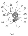
- Fig. 4 presents detail of an embodiment of one jaw of the transferring element.
- Fig. 5 presents the transferring element with various alternatives of design of the jaw.
- Fig. 6 shows the transferring element with examples of the shape of transferred products.
- Fig. 7 presents a schematic graphic representation of the area that pressurized air acts on.
- the pusher mechanism of a glass forming machine is used to transfer formed glass products 2 or groups of products 2 from the fixed dead plate 1 of the glass forming machine on a moving conveyor belt 3.
- Various design alternatives of the pusher mechanism are well-known and they will not be described in detail since the invention deals with the transferring element of the pusher mechanism only. This is why it is just the transferring element 10 of the pusher mechanism that is displayed in the drawings.
- Figs. 1 to 3 present a transferring element 10 designed for transferring three products 2 (glass bottles) at the same time from the fixed dead plate 1 to the conveyor belt 3 which moves in the direction indicated by the arrow 41 (see fig. 2 ).
- Fig. 2 also shows the direction 42 of the movement of products 2 during transferring.
- the transferring element 10 comprises of a holder 11 that has two clamping form grooves 27 arranged in parallel above each other for adjustable installation of the jaw 20.
- the clamping form grooves 27 there are square nuts 29 (see figs. 3 and 4 ) into which fixing bolts 24 are screwed that hold the jaws 20 in a selected place on the holder 11 after tightening.
- Each jaw 20 has a base 12 and an arm 13 arranged in a perpendicular way to it.
- the base 12 of the jaw 20 is equipped with a replaceable lateral contact insert 21 and the arm 13 of the jaw 20 is equipped with a replaceable front contact insert 22.
- the replaceable contact inserts 21, 22 are made of heat-resistant material and they protect the hot glass product 2 from being damaged by the jaw 20.
- each jaw 20 is equipped with a nozzle 23 that is oriented upwards, parallel to the arm 13 and product axis 2.
- Each nozzle 23 is connected through a distribution channel 34 in the jaw 20 to the distribution space 33 of an elongated shape into which the corresponding outlet from the common distribution channel 32 created in the holder 11 leads.
- the elongated shape of the distribution space 33 makes it possible for the distribution channel 34 in the jaw 20 to be connected to the distribution channel 32 in the holder 11 even if the jaw 20 is moved in the adjustment direction 43 (see fig. 3 ).
- the distribution space 33 is sealed with a gasket 26 along the perimeter. Pressurized air is brought to the distribution channel 32 in the holder 11 through the central supply line 31. Technological borings that are necessary for the production of channels are blinded with plugs.
- the transferring element 10 is equipped with L-shaped jaws 20 that are fixed to the holder 11 in an adjustable way and have a base 12 and an arm 13 that is oriented in the perpendicular direction to the base 12.
- fig. 5 shows that the jaws 20 can also be U-shaped as besides the arm 13 there is an auxiliary arm 14 connected to the base 12.
- the arm 13 is connected directly to the holder 11 so the holder body 11 directly forms the base 12 of this jaw 20.
- the nozzle 23 according to the invention can be also used in transferring elements 10 where the jaws 20 are connected to the holder 11 in a fixed way or where the jaws 20 and the holder 11 are made of one piece of material.
- the corner between the base 12 and the arm 13 forms a vacuum channel 28 (see fig. 6 ) in the lower part of which the nozzle 23 is installed.
- Cross section of the vacuum channel 28 can be modified by forming of the base 12 and arm 13 of the jaw 20 or by forming of the replaceable contact inserts 21, 22.
- pressurized air is routed from a source (not shown) via a central supply line 31 to the distribution channel 32 in the holder 11.
- Pressurized air is routed through the distribution channel 32 in the holder 11 to the distribution channels 34 in the jaws 20.
- pressurized air leaves the nozzle 23 and flows upwards through the vacuum channel 28 formed by the walls of the jaw 20 in the corner between the base 12 and arm 13 and the side wall of the product 2.
- This vertical stream 30 of air (see figs. 1 and 7 ) is parallel to the vertical axis of the product 2.
- the speed of the air stream 30 increases considerably, which results in a drop of the total air pressure in the area after the nozzle 23, i.e. in the vacuum channel 28.
- the result of this phenomenon is force 40 that draws the product 2 into the jaw 20.
- the force 40 exerted by the vertical stream 30 of air is higher than the one in the case of known structures with horizontal blowing as the air stream 30 flows vertically around the product 2 and acts on a larger area 44 of the product 2 (see fig. 7 ).
- the inlet of pressurized air to the transferring element 10 is closed when the transferring element 10 with the jaws 20 has transferred the products 2 in the direction 42 (see fig. 2 ) from the fixed dead plate 1 onto the moving conveyor belt 3. Due to the interruption of the supply of pressurized air, the force 40 that drew the products 2 into the jaws 20 ceases to act, so the products 2 can be carried by the conveyor belt 3 to the next production operation.
- the transferring element 10 according to the invention can also transfer products 2 with a non-circular cross-section. Examples of such products are presented schematically in fig. 6 .
- the angle ⁇ (see fig. 6 ) between the arm 13 of the jaw 20 and the base 12 of the jaw 20 is generally 90°.
- ⁇ can be used.
Landscapes
- Engineering & Computer Science (AREA)
- Chemical & Material Sciences (AREA)
- Manufacturing & Machinery (AREA)
- Materials Engineering (AREA)
- Organic Chemistry (AREA)
- Re-Forming, After-Treatment, Cutting And Transporting Of Glass Products (AREA)
- Manipulator (AREA)
- Encapsulation Of And Coatings For Semiconductor Or Solid State Devices (AREA)
- Steering Control In Accordance With Driving Conditions (AREA)
- Window Of Vehicle (AREA)
- Perforating, Stamping-Out Or Severing By Means Other Than Cutting (AREA)
Applications Claiming Priority (2)
| Application Number | Priority Date | Filing Date | Title |
|---|---|---|---|
| CZ20040513A CZ296595B6 (cs) | 2004-04-19 | 2004-04-19 | Presouvací clen mechanizmu odstávky sklárského tvarovacího stroje |
| PCT/CZ2005/000030 WO2005100271A1 (en) | 2004-04-19 | 2005-03-29 | Transferring element of a pusher mechanism of a glass forming machine |
Publications (2)
| Publication Number | Publication Date |
|---|---|
| EP1737798A1 EP1737798A1 (en) | 2007-01-03 |
| EP1737798B1 true EP1737798B1 (en) | 2008-07-09 |
Family
ID=34963690
Family Applications (1)
| Application Number | Title | Priority Date | Filing Date |
|---|---|---|---|
| EP05714862A Expired - Lifetime EP1737798B1 (en) | 2004-04-19 | 2005-03-29 | Transferring element of a pusher mechanism of a glass forming machine |
Country Status (8)
| Country | Link |
|---|---|
| EP (1) | EP1737798B1 (cs) |
| AT (1) | ATE400534T1 (cs) |
| CZ (1) | CZ296595B6 (cs) |
| DE (1) | DE602005008028D1 (cs) |
| EA (1) | EA008355B1 (cs) |
| ES (1) | ES2310336T3 (cs) |
| UA (1) | UA83130C2 (cs) |
| WO (1) | WO2005100271A1 (cs) |
Families Citing this family (4)
| Publication number | Priority date | Publication date | Assignee | Title |
|---|---|---|---|---|
| US7320230B2 (en) * | 2005-11-07 | 2008-01-22 | Emhart Glass Sa | Pushout mechanism for I.S. machine |
| US7765833B2 (en) | 2006-03-20 | 2010-08-03 | Poco Graphite, Inc. | Apparatus for adjustable stacker bar assembly having quick change features |
| EP3216769B1 (en) * | 2016-03-07 | 2018-08-29 | BDF Industries S.p.A. | A handling unit for hollow glass articles |
| CN107777354B (zh) * | 2017-11-24 | 2023-06-06 | 山东三金玻璃机械有限公司 | 一种制瓶机拨瓶装置及吸附瓶体输送方法 |
Family Cites Families (4)
| Publication number | Priority date | Publication date | Assignee | Title |
|---|---|---|---|---|
| GB9023103D0 (en) * | 1990-10-24 | 1990-12-05 | Emhart Ind | Push out device for a glassware forming machine |
| US5527372A (en) * | 1994-08-24 | 1996-06-18 | Emhart Glass Machinery Investments Inc. | Pusher mechanism for I.S. glass forming machine |
| DE29902149U1 (de) * | 1999-02-06 | 1999-08-05 | Fa. Hermann Heye, 31683 Obernkirchen | Vorrichtung zum Überschieben hohler Glasgegenstände auf ein Transportband |
| DE19957079B4 (de) * | 1999-11-26 | 2004-03-11 | Heye International Gmbh | Vorrichtung zum Überschieben von Glasgegenständen |
-
2004
- 2004-04-19 CZ CZ20040513A patent/CZ296595B6/cs not_active IP Right Cessation
-
2005
- 2005-03-29 EA EA200601640A patent/EA008355B1/ru not_active IP Right Cessation
- 2005-03-29 DE DE602005008028T patent/DE602005008028D1/de not_active Expired - Lifetime
- 2005-03-29 EP EP05714862A patent/EP1737798B1/en not_active Expired - Lifetime
- 2005-03-29 AT AT05714862T patent/ATE400534T1/de not_active IP Right Cessation
- 2005-03-29 ES ES05714862T patent/ES2310336T3/es not_active Expired - Lifetime
- 2005-03-29 UA UAA200610987A patent/UA83130C2/ru unknown
- 2005-03-29 WO PCT/CZ2005/000030 patent/WO2005100271A1/en not_active Ceased
Also Published As
| Publication number | Publication date |
|---|---|
| EA008355B1 (ru) | 2007-04-27 |
| CZ296595B6 (cs) | 2006-04-12 |
| EA200601640A1 (ru) | 2007-02-27 |
| UA83130C2 (ru) | 2008-06-10 |
| DE602005008028D1 (de) | 2008-08-21 |
| WO2005100271A1 (en) | 2005-10-27 |
| ES2310336T3 (es) | 2009-01-01 |
| EP1737798A1 (en) | 2007-01-03 |
| CZ2004513A3 (cs) | 2006-02-15 |
| ATE400534T1 (de) | 2008-07-15 |
Similar Documents
| Publication | Publication Date | Title |
|---|---|---|
| US9010520B2 (en) | Module for transferring a component between two positions | |
| KR102020573B1 (ko) | 성형 기기 | |
| US8418946B2 (en) | Crusher for crushing a silicon lump, and silicon lump crushing apparatus having a plurality of crushers | |
| CN105945111B (zh) | 一种片料件自动压型设备 | |
| US6494063B1 (en) | Apparatus for pushing hollow glass articles onto a conveyor belt | |
| ITBO980244A1 (it) | Macchina automatica per la produzione, per il controllo, per il riempi mento e per la tappatura di flaconi di materia termoplastica. | |
| US20120223468A1 (en) | Device for handling workpieces | |
| CN108297344A (zh) | 一种轴承滚轮自动嵌入注塑生产线 | |
| CN101497399A (zh) | 自动分料机 | |
| US5056648A (en) | Push cut device | |
| EP3121017B1 (en) | Machine for printing simultaneously on two parallel surfaces | |
| US4265073A (en) | Apparatus for forming and overwrapping batches of products | |
| EP1737798B1 (en) | Transferring element of a pusher mechanism of a glass forming machine | |
| CA2360729C (en) | Device and method for pushing glass objects | |
| GB2117019A (en) | Positioning of flat textile articles | |
| JPH0397631A (ja) | ガラス容器の押し出し装置 | |
| CN104148784A (zh) | 一种超短热管自动焊接机 | |
| JP2003212566A (ja) | I.s.成形機 | |
| JP2003201131A (ja) | 搬出機構 | |
| CN204545884U (zh) | 一种螺丝机供料机构 | |
| CN207748410U (zh) | 凸轮轴输送机 | |
| DE602006020217D1 (de) | Schubverfahren und Vorrichtung zum Überführen von Glasartikeln | |
| CN201102329Y (zh) | 垫块铣切机原料夹紧装置 | |
| JP4499632B2 (ja) | 自動プレス設備 | |
| CZ14538U1 (cs) | Přesouvací člen mechanizmu odstávky sklářského tvarovacího stroje |
Legal Events
| Date | Code | Title | Description |
|---|---|---|---|
| PUAI | Public reference made under article 153(3) epc to a published international application that has entered the european phase |
Free format text: ORIGINAL CODE: 0009012 |
|
| 17P | Request for examination filed |
Effective date: 20060905 |
|
| AK | Designated contracting states |
Kind code of ref document: A1 Designated state(s): AT BE BG CH CY CZ DE DK EE ES FI FR GB GR HU IE IS IT LI LT LU MC NL PL PT RO SE SI SK TR |
|
| DAX | Request for extension of the european patent (deleted) | ||
| GRAP | Despatch of communication of intention to grant a patent |
Free format text: ORIGINAL CODE: EPIDOSNIGR1 |
|
| GRAS | Grant fee paid |
Free format text: ORIGINAL CODE: EPIDOSNIGR3 |
|
| GRAA | (expected) grant |
Free format text: ORIGINAL CODE: 0009210 |
|
| AK | Designated contracting states |
Kind code of ref document: B1 Designated state(s): AT BE BG CH CY CZ DE DK EE ES FI FR GB GR HU IE IS IT LI LT LU MC NL PL PT RO SE SI SK TR |
|
| REG | Reference to a national code |
Ref country code: GB Ref legal event code: FG4D |
|
| REG | Reference to a national code |
Ref country code: CH Ref legal event code: EP |
|
| REF | Corresponds to: |
Ref document number: 602005008028 Country of ref document: DE Date of ref document: 20080821 Kind code of ref document: P |
|
| REG | Reference to a national code |
Ref country code: IE Ref legal event code: FG4D |
|
| REG | Reference to a national code |
Ref country code: CH Ref legal event code: NV Representative=s name: WERNER BRUDERER PATENTANWALT |
|
| REG | Reference to a national code |
Ref country code: ES Ref legal event code: FG2A Ref document number: 2310336 Country of ref document: ES Kind code of ref document: T3 |
|
| NLV1 | Nl: lapsed or annulled due to failure to fulfill the requirements of art. 29p and 29m of the patents act | ||
| PG25 | Lapsed in a contracting state [announced via postgrant information from national office to epo] |
Ref country code: NL Free format text: LAPSE BECAUSE OF FAILURE TO SUBMIT A TRANSLATION OF THE DESCRIPTION OR TO PAY THE FEE WITHIN THE PRESCRIBED TIME-LIMIT Effective date: 20080709 Ref country code: IS Free format text: LAPSE BECAUSE OF FAILURE TO SUBMIT A TRANSLATION OF THE DESCRIPTION OR TO PAY THE FEE WITHIN THE PRESCRIBED TIME-LIMIT Effective date: 20081109 Ref country code: LT Free format text: LAPSE BECAUSE OF FAILURE TO SUBMIT A TRANSLATION OF THE DESCRIPTION OR TO PAY THE FEE WITHIN THE PRESCRIBED TIME-LIMIT Effective date: 20080709 |
|
| PG25 | Lapsed in a contracting state [announced via postgrant information from national office to epo] |
Ref country code: FI Free format text: LAPSE BECAUSE OF FAILURE TO SUBMIT A TRANSLATION OF THE DESCRIPTION OR TO PAY THE FEE WITHIN THE PRESCRIBED TIME-LIMIT Effective date: 20080709 Ref country code: BG Free format text: LAPSE BECAUSE OF FAILURE TO SUBMIT A TRANSLATION OF THE DESCRIPTION OR TO PAY THE FEE WITHIN THE PRESCRIBED TIME-LIMIT Effective date: 20081009 Ref country code: SI Free format text: LAPSE BECAUSE OF FAILURE TO SUBMIT A TRANSLATION OF THE DESCRIPTION OR TO PAY THE FEE WITHIN THE PRESCRIBED TIME-LIMIT Effective date: 20080709 Ref country code: PT Free format text: LAPSE BECAUSE OF FAILURE TO SUBMIT A TRANSLATION OF THE DESCRIPTION OR TO PAY THE FEE WITHIN THE PRESCRIBED TIME-LIMIT Effective date: 20081209 |
|
| PG25 | Lapsed in a contracting state [announced via postgrant information from national office to epo] |
Ref country code: BE Free format text: LAPSE BECAUSE OF FAILURE TO SUBMIT A TRANSLATION OF THE DESCRIPTION OR TO PAY THE FEE WITHIN THE PRESCRIBED TIME-LIMIT Effective date: 20080709 |
|
| PG25 | Lapsed in a contracting state [announced via postgrant information from national office to epo] |
Ref country code: DK Free format text: LAPSE BECAUSE OF FAILURE TO SUBMIT A TRANSLATION OF THE DESCRIPTION OR TO PAY THE FEE WITHIN THE PRESCRIBED TIME-LIMIT Effective date: 20080709 Ref country code: EE Free format text: LAPSE BECAUSE OF FAILURE TO SUBMIT A TRANSLATION OF THE DESCRIPTION OR TO PAY THE FEE WITHIN THE PRESCRIBED TIME-LIMIT Effective date: 20080709 |
|
| PLBE | No opposition filed within time limit |
Free format text: ORIGINAL CODE: 0009261 |
|
| STAA | Information on the status of an ep patent application or granted ep patent |
Free format text: STATUS: NO OPPOSITION FILED WITHIN TIME LIMIT |
|
| PG25 | Lapsed in a contracting state [announced via postgrant information from national office to epo] |
Ref country code: RO Free format text: LAPSE BECAUSE OF FAILURE TO SUBMIT A TRANSLATION OF THE DESCRIPTION OR TO PAY THE FEE WITHIN THE PRESCRIBED TIME-LIMIT Effective date: 20080709 Ref country code: SK Free format text: LAPSE BECAUSE OF FAILURE TO SUBMIT A TRANSLATION OF THE DESCRIPTION OR TO PAY THE FEE WITHIN THE PRESCRIBED TIME-LIMIT Effective date: 20080709 Ref country code: CZ Free format text: LAPSE BECAUSE OF FAILURE TO SUBMIT A TRANSLATION OF THE DESCRIPTION OR TO PAY THE FEE WITHIN THE PRESCRIBED TIME-LIMIT Effective date: 20080709 |
|
| 26N | No opposition filed |
Effective date: 20090414 |
|
| PGFP | Annual fee paid to national office [announced via postgrant information from national office to epo] |
Ref country code: TR Payment date: 20090306 Year of fee payment: 5 |
|
| PG25 | Lapsed in a contracting state [announced via postgrant information from national office to epo] |
Ref country code: MC Free format text: LAPSE BECAUSE OF NON-PAYMENT OF DUE FEES Effective date: 20090331 |
|
| REG | Reference to a national code |
Ref country code: CH Ref legal event code: PL |
|
| REG | Reference to a national code |
Ref country code: IE Ref legal event code: MM4A |
|
| PG25 | Lapsed in a contracting state [announced via postgrant information from national office to epo] |
Ref country code: CH Free format text: LAPSE BECAUSE OF NON-PAYMENT OF DUE FEES Effective date: 20090331 Ref country code: SE Free format text: LAPSE BECAUSE OF FAILURE TO SUBMIT A TRANSLATION OF THE DESCRIPTION OR TO PAY THE FEE WITHIN THE PRESCRIBED TIME-LIMIT Effective date: 20081009 Ref country code: IE Free format text: LAPSE BECAUSE OF NON-PAYMENT OF DUE FEES Effective date: 20090329 Ref country code: LI Free format text: LAPSE BECAUSE OF NON-PAYMENT OF DUE FEES Effective date: 20090331 |
|
| REG | Reference to a national code |
Ref country code: ES Ref legal event code: FD2A Effective date: 20090330 |
|
| PG25 | Lapsed in a contracting state [announced via postgrant information from national office to epo] |
Ref country code: PL Free format text: LAPSE BECAUSE OF FAILURE TO SUBMIT A TRANSLATION OF THE DESCRIPTION OR TO PAY THE FEE WITHIN THE PRESCRIBED TIME-LIMIT Effective date: 20080709 |
|
| PGFP | Annual fee paid to national office [announced via postgrant information from national office to epo] |
Ref country code: IT Payment date: 20100326 Year of fee payment: 6 |
|
| PG25 | Lapsed in a contracting state [announced via postgrant information from national office to epo] |
Ref country code: AT Free format text: LAPSE BECAUSE OF NON-PAYMENT OF DUE FEES Effective date: 20090329 |
|
| PGFP | Annual fee paid to national office [announced via postgrant information from national office to epo] |
Ref country code: GB Payment date: 20100303 Year of fee payment: 6 |
|
| PG25 | Lapsed in a contracting state [announced via postgrant information from national office to epo] |
Ref country code: ES Free format text: LAPSE BECAUSE OF NON-PAYMENT OF DUE FEES Effective date: 20090330 |
|
| PGFP | Annual fee paid to national office [announced via postgrant information from national office to epo] |
Ref country code: FR Payment date: 20100416 Year of fee payment: 6 |
|
| PGFP | Annual fee paid to national office [announced via postgrant information from national office to epo] |
Ref country code: DE Payment date: 20100521 Year of fee payment: 6 |
|
| PG25 | Lapsed in a contracting state [announced via postgrant information from national office to epo] |
Ref country code: GR Free format text: LAPSE BECAUSE OF FAILURE TO SUBMIT A TRANSLATION OF THE DESCRIPTION OR TO PAY THE FEE WITHIN THE PRESCRIBED TIME-LIMIT Effective date: 20081010 |
|
| PG25 | Lapsed in a contracting state [announced via postgrant information from national office to epo] |
Ref country code: LU Free format text: LAPSE BECAUSE OF NON-PAYMENT OF DUE FEES Effective date: 20090329 |
|
| PG25 | Lapsed in a contracting state [announced via postgrant information from national office to epo] |
Ref country code: HU Free format text: LAPSE BECAUSE OF FAILURE TO SUBMIT A TRANSLATION OF THE DESCRIPTION OR TO PAY THE FEE WITHIN THE PRESCRIBED TIME-LIMIT Effective date: 20090110 |
|
| PG25 | Lapsed in a contracting state [announced via postgrant information from national office to epo] |
Ref country code: CY Free format text: LAPSE BECAUSE OF FAILURE TO SUBMIT A TRANSLATION OF THE DESCRIPTION OR TO PAY THE FEE WITHIN THE PRESCRIBED TIME-LIMIT Effective date: 20080709 |
|
| GBPC | Gb: european patent ceased through non-payment of renewal fee |
Effective date: 20110329 |
|
| REG | Reference to a national code |
Ref country code: FR Ref legal event code: ST Effective date: 20111130 |
|
| PG25 | Lapsed in a contracting state [announced via postgrant information from national office to epo] |
Ref country code: DE Free format text: LAPSE BECAUSE OF NON-PAYMENT OF DUE FEES Effective date: 20111001 Ref country code: FR Free format text: LAPSE BECAUSE OF NON-PAYMENT OF DUE FEES Effective date: 20110331 |
|
| REG | Reference to a national code |
Ref country code: DE Ref legal event code: R119 Ref document number: 602005008028 Country of ref document: DE Effective date: 20111001 |
|
| PG25 | Lapsed in a contracting state [announced via postgrant information from national office to epo] |
Ref country code: IT Free format text: LAPSE BECAUSE OF NON-PAYMENT OF DUE FEES Effective date: 20110329 Ref country code: GB Free format text: LAPSE BECAUSE OF NON-PAYMENT OF DUE FEES Effective date: 20110329 |
|
| PG25 | Lapsed in a contracting state [announced via postgrant information from national office to epo] |
Ref country code: TR Free format text: LAPSE BECAUSE OF NON-PAYMENT OF DUE FEES Effective date: 20100329 |