EP1738112B1 - Raketentriebwerk mit dämpfung von schwingungen der brennkammer durch resonatoren - Google Patents
Raketentriebwerk mit dämpfung von schwingungen der brennkammer durch resonatoren Download PDFInfo
- Publication number
- EP1738112B1 EP1738112B1 EP05732027.7A EP05732027A EP1738112B1 EP 1738112 B1 EP1738112 B1 EP 1738112B1 EP 05732027 A EP05732027 A EP 05732027A EP 1738112 B1 EP1738112 B1 EP 1738112B1
- Authority
- EP
- European Patent Office
- Prior art keywords
- combustion chamber
- chamber
- resonators
- injection
- resonator
- Prior art date
- Legal status (The legal status is an assumption and is not a legal conclusion. Google has not performed a legal analysis and makes no representation as to the accuracy of the status listed.)
- Expired - Lifetime
Links
- 238000002485 combustion reaction Methods 0.000 title claims description 74
- 238000013016 damping Methods 0.000 title claims description 20
- 238000002347 injection Methods 0.000 claims description 55
- 239000007924 injection Substances 0.000 claims description 55
- 239000000446 fuel Substances 0.000 claims description 36
- 230000010355 oscillation Effects 0.000 claims description 6
- 238000011144 upstream manufacturing Methods 0.000 claims description 6
- 239000012530 fluid Substances 0.000 claims 4
- 239000007789 gas Substances 0.000 description 7
- 238000001816 cooling Methods 0.000 description 6
- 239000000567 combustion gas Substances 0.000 description 3
- 230000006378 damage Effects 0.000 description 3
- 238000005516 engineering process Methods 0.000 description 3
- 239000001257 hydrogen Substances 0.000 description 3
- 150000002431 hydrogen Chemical class 0.000 description 3
- 229910052739 hydrogen Inorganic materials 0.000 description 3
- 230000002238 attenuated effect Effects 0.000 description 2
- 238000010276 construction Methods 0.000 description 2
- 230000000694 effects Effects 0.000 description 2
- 239000007788 liquid Substances 0.000 description 2
- MYMOFIZGZYHOMD-UHFFFAOYSA-N Dioxygen Chemical compound O=O MYMOFIZGZYHOMD-UHFFFAOYSA-N 0.000 description 1
- UFHFLCQGNIYNRP-UHFFFAOYSA-N Hydrogen Chemical compound [H][H] UFHFLCQGNIYNRP-UHFFFAOYSA-N 0.000 description 1
- 239000006096 absorbing agent Substances 0.000 description 1
- 238000010521 absorption reaction Methods 0.000 description 1
- 230000006978 adaptation Effects 0.000 description 1
- 238000004891 communication Methods 0.000 description 1
- 230000006735 deficit Effects 0.000 description 1
- 239000002737 fuel gas Substances 0.000 description 1
- 238000010438 heat treatment Methods 0.000 description 1
- 238000000034 method Methods 0.000 description 1
- 238000013021 overheating Methods 0.000 description 1
Images

Classifications
-
- F—MECHANICAL ENGINEERING; LIGHTING; HEATING; WEAPONS; BLASTING
- F23—COMBUSTION APPARATUS; COMBUSTION PROCESSES
- F23R—GENERATING COMBUSTION PRODUCTS OF HIGH PRESSURE OR HIGH VELOCITY, e.g. GAS-TURBINE COMBUSTION CHAMBERS
- F23R3/00—Continuous combustion chambers using liquid or gaseous fuel
- F23R3/28—Continuous combustion chambers using liquid or gaseous fuel characterised by the fuel supply
-
- F—MECHANICAL ENGINEERING; LIGHTING; HEATING; WEAPONS; BLASTING
- F23—COMBUSTION APPARATUS; COMBUSTION PROCESSES
- F23M—CASINGS, LININGS, WALLS OR DOORS SPECIALLY ADAPTED FOR COMBUSTION CHAMBERS, e.g. FIREBRIDGES; DEVICES FOR DEFLECTING AIR, FLAMES OR COMBUSTION PRODUCTS IN COMBUSTION CHAMBERS; SAFETY ARRANGEMENTS SPECIALLY ADAPTED FOR COMBUSTION APPARATUS; DETAILS OF COMBUSTION CHAMBERS, NOT OTHERWISE PROVIDED FOR
- F23M20/00—Details of combustion chambers, not otherwise provided for, e.g. means for storing heat from flames
- F23M20/005—Noise absorbing means
-
- F—MECHANICAL ENGINEERING; LIGHTING; HEATING; WEAPONS; BLASTING
- F23—COMBUSTION APPARATUS; COMBUSTION PROCESSES
- F23C—METHODS OR APPARATUS FOR COMBUSTION USING FLUID FUEL OR SOLID FUEL SUSPENDED IN A CARRIER GAS OR AIR
- F23C2900/00—Special features of, or arrangements for combustion apparatus using fluid fuels or solid fuels suspended in air; Combustion processes therefor
- F23C2900/9901—Combustion process using hydrogen, hydrogen peroxide water or brown gas as fuel
-
- F—MECHANICAL ENGINEERING; LIGHTING; HEATING; WEAPONS; BLASTING
- F23—COMBUSTION APPARATUS; COMBUSTION PROCESSES
- F23R—GENERATING COMBUSTION PRODUCTS OF HIGH PRESSURE OR HIGH VELOCITY, e.g. GAS-TURBINE COMBUSTION CHAMBERS
- F23R2900/00—Special features of, or arrangements for continuous combustion chambers; Combustion processes therefor
- F23R2900/00014—Reducing thermo-acoustic vibrations by passive means, e.g. by Helmholtz resonators
Definitions
- the present invention relates to a rocket engine with a device for damping vibrations of a combustion chamber, wherein at least one resonator is vibrationally connected to the combustion chamber.
- Damping chambers are arranged in the region of the injection head in a fuel distribution space and connected via passage channels with the combustion chamber vibration technology.
- the fuel distribution space which serves for example for the distribution of hydrogen, although an active cooling of the damping chambers is ensured.
- this relatively complex design measures are necessary. Nevertheless, it can not be ruled out that hot combustion chamber combustion gases penetrate directly into the damping chambers via the passage channels and lead to impairment or even destruction of the damping chambers.
- the apparatus includes a resonator positioned between a diffuser outlet and fuel-air mixers disposed within the combustor.
- the resonator is formed by a plurality of resonator tubes disposed around the combustor and each having an end open toward the interior of the combustor.
- DE 101 63 561 A1 discloses a rocket engine comprising a combustion chamber, means for damping vibrations of the combustion chamber and an antechamber, the vibration damping means comprising at least one resonator vibrationally connected to the combustion chamber, the combustion chamber being upstream of an injection head; wherein in the injection head at least one injection element for introducing a fuel flow is provided in the combustion chamber, and wherein the prechamber is connected via at least one passage passage with the combustion chamber vibration technology.
- the object of the present invention is therefore to provide an improved possibility for damping vibrations of a combustion chamber with the aid of resonators.
- the invention relates to a device for damping vibrations of a combustion chamber, wherein at least one resonator is vibrationally connected to the combustion chamber.
- the at least one resonator is vibrationally connected to an antechamber and the prechamber is connected in terms of vibration technology via at least one passage channel to the combustion chamber.
- This ensures that the one or more resonators that are used to dampen the vibrations, no longer directly with the combustion chamber, or with the interior of the combustion chamber in communication. Rather, there is only an indirect connection via the intermediate antechamber.
- the resonators can be arranged in areas that are subjected to a lower temperature load or lower temperature changes. Nevertheless, the vibrations of the combustion chamber via the passage channel and the antechamber can reach up to the resonators and thus the vibrations of the combustion chamber can be effectively damped.
- a first embodiment of the invention provides that the combustion chamber adjoins an injection head with at least one injection element, which is designed to introduce a gaseous fuel flow into the combustion chamber, and the pre-chamber is arranged in terms of flow before the at least one injection element. It can be provided a single fuel stream, which is supplied to the combustion chamber. It is also possible to provide two or more fuel streams which are supplied to the combustion chamber through the injection elements and, if appropriate, are already mixed in or immediately after the injection elements.
- the pre-chamber is arranged in this alternative in an area that passes at least one of the fuel streams before it flows through the injector or the injection elements. So that are the injection elements between the combustion chamber or the interior of the combustion chamber and the antechamber.
- the combustion chamber adjoins an injection head with at least one injection element, which is designed to introduce a fuel flow into the combustion chamber, and the pre-chamber is arranged in terms of flow in the region of the at least one injection element.
- the pre-chamber is in an area that passes at least one of the fuel streams, while it flows through the injection element or elements.
- the injection elements and the pre-chamber are fluidly arranged side by side in front of the combustion chamber or the interior of the combustion chamber.
- At least one of the fuel streams can serve to keep the temperature of the resonators largely constant by actively cooling the resonators.
- the prechamber fluidly communicate with a fuel flow before it reaches the interior of the combustion chamber.
- the fuel flow is thereby not only diverted around a resonator as in the case of DE 34 32 607 A1 but it reaches the interior of the resonator, so that the resonance volume of the resonator itself can be kept substantially constant at the temperature of the fuel flow.
- the resonator as well as the antechamber with a gaseous fuel flow in conjunction since then on the fuel flow, a particularly good vibration control connection between the resonator and the combustion chamber can be ensured.
- the passage channel is formed as part of an injection element. In principle, however, it is also possible to provide separate passageways which guarantee a vibration-technical connection between the interior of the combustion chamber and the prechamber.
- the resonators can be designed, for example, as Helmholtz resonators or as ⁇ / 4 resonators. Such resonators are basically well known from the prior art.
- acoustic resonators known from the cited prior art.
- Helmoltz resonators Both resonator types consist of small volumes, which are directly connected to the chamber in the prior art devices. In these resonators, a dissipation of the vibration energy takes place when the excited frequency of the chamber coincides with the natural frequency of the resonator.
- Resonators are narrow-band absorbers and must therefore be tuned to the frequency to be damped.
- Helmholtz resonators are used for attenuation in a wider frequency range compared to the ⁇ / 4 resonators, which must be tuned to a discrete frequency.
- arranged resonators in the region of the injection head form undesirable sudströmzonen in this area, whereby an additional heat flow in the direction of the injection head is formed, which may affect the stability of the injection head.
- the present invention provides a resonator assembly which is independent of the hot combustion gases and thus the temperature in the combustion chamber. At the same time a negative influence on the arrangement of the injection elements and the combustion chamber cooling is avoided.
- the invention is particularly applicable to mainstream engines and other gaseous injection engines of one or two or more fuel components.
- mainstream propulsion systems gaseous exhaust gases from a fuel turbine are returned to a fuel stream (main stream) and sent into the combustion chamber along with the fuel stream.
- a gaseous fuel such as hydrogen.
- the fuel is passed in liquid form through cooling channels of the rocket engine and converted into gaseous state due to the heat absorption.
- gaseous fuel streams which are passed through injection elements in the interior of a combustion chamber and burned there.
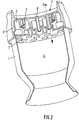
- Fig. 1 to 3 show examples of a mainstream rocket engine.
- the engine each has a combustion chamber 1, which is bounded upstream by an injection plate 2 of an injection head 3.
- injection elements 4 are arranged, which serve to direct one or more fuel flows into the interior 9 of the combustion chamber 1.
- the injection head 3 is bounded upstream by a cover plate 6.
- the injection elements 4 are either tubular, but they can also be formed by a combination of tubes and one or more coaxial sleeves.
- the injection elements 4 or the tubes or sleeves are connected to the injection plate 2 and / or the cover plate 6.
- the main flow of a gaseous fuel and turbine exhaust gases (gas) reach an antechamber 7 in front of the injection head and are then passed through the injection elements 4 into the interior 9 of the combustion chamber 1.
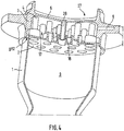
- Fig. 4 shows an expander-cycle engine, in which a gaseous fuel stream such as hydrogen (gH2) is passed into an antechamber 17 and from there via annular gaps 8 between a pipe 28 and a sleeve of a coaxial injection element 4 in the interior 9 of the combustion chamber passes , Via another chamber 27 and the tube 28, another, for example, liquid fuel stream such as liquid oxygen enters the interior 9 of the combustion chamber first
- a gaseous fuel stream such as hydrogen (gH2)
- Fig. 1 shows an arrangement of a Helmholtz resonator 5 in the wall of the antechamber 7.
- the Helmholtz resonator 5 as a circular circumferential Chamber may be formed in the wall of the prechamber 7, which is connected via an annular passage gap with the prechamber 7, as in Fig. 1 shown.
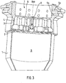
- Fig. 2 shows an alternative embodiment, wherein ⁇ / 4 resonators 5 are arranged in the form of unilaterally open cylinders in the cover plate 6 of the injection head 3. As in Fig. 2 shown, a plurality of ⁇ / 4 resonators 5 may be arranged uniformly distributed. In the case of Fig. 2 the ⁇ / 4 resonators 5 are arranged annularly around the central axis of the cover plate 6.
- ⁇ / 4 resonators 5a, 5b in the wall of the prechamber 7 is provided.
- the ⁇ / 4 resonators 5a, 5b are formed as holes in the wall of the prechamber 7. These ⁇ / 4 resonators 5a, 5b can also be distributed uniformly.
- the ⁇ / 4 resonators 5a, 5b are arranged in two superimposed rings in the wall of the prechamber 7.
- ⁇ / 4 resonators 5, 5a, 5b are basically identical in design, in order to damp exactly one defined oscillation frequency.
- the ⁇ / 4 resonators 5, 5a, 5b may be formed differently, so that in each case a group of ⁇ / 4 resonators 5, 5a, 5b is adapted to a specific oscillation frequency.
- the lower ⁇ / 4 resonators 5a are formed as shorter holes and thus adapted to higher vibration frequencies than the upper ⁇ / 4 resonators 5b, which are formed as longer holes.
- the determination of the geometrical dimensions has to take into account the respective temperature conditions of the gas in the region of the resonators, since this has a direct influence on the speed of sound and thus also on the frequency.
- ⁇ / 4 resonators 5 are provided as holes in the wall of the injection head 3 in the region of an antechamber 17, which encloses the injection elements 4.
- the ⁇ / 4 resonators 5 can be uniformly distributed, for example, annularly, be arranged in the wall of the injection head 3 and there may also be several groups of ⁇ / 4 resonators 5 with different adaptation to different vibration frequencies.
- gaseous fuel such as gH2 enters the pre-chamber 17 and is introduced via annular gaps 8 into the interior 9 of the combustion chamber 1.
- This flow path of the gaseous fuel is a vibration connection between the interior 9 of the combustion chamber 1 and the antechamber 17, analogous to the above statements to the FIGS. 1 to 3 ,
- these vibrations reach the ⁇ / 4 resonators 5 in the wall of the antechamber 17 and can be effectively attenuated there by the resonator effect of the ⁇ / 4 resonators 5.
- the essential advantage of the invention is the largely constant temperature of the gas in the resonators 5, 5a, 5b during the entire duration of the operation of the engine. Furthermore, there is a simplification of the construction in the high-temperature region of the combustion chamber 1, since in the region of the wall of the combustion chamber 1 and in the injection plate in addition to the usual cooling no further arrangements such as resonators more must be provided. In addition, the construction according to the present invention enables a much higher number of resonator examples to be accommodated, since the individual embodiments according to FIGS FIGS.
- Helmholtz resonators 5 and / or ⁇ / 4 resonators 5a, 5b in the wall of the prechamber 7 and / or ⁇ / 4 resonators 5 can be provided in the cover plate 6.
Landscapes
- Engineering & Computer Science (AREA)
- Chemical & Material Sciences (AREA)
- Combustion & Propulsion (AREA)
- Mechanical Engineering (AREA)
- General Engineering & Computer Science (AREA)
- Combustion Methods Of Internal-Combustion Engines (AREA)
Description
- Die vorliegende Erfindung betrifft ein Raketentriebwerk mit einer Einrichtung zum Dämpfen von Schwingungen einer Brennkammer, wobei mindestens ein Resonator schwingungstechnisch mit der Brennkammer verbunden ist.
- Solche Einrichtungen sind grundsätzlich aus dem Stand der Technik bekannt. Sowohl
DE 34 32 607 A1 als auchUS 5,353,598 A beschreiben Einrichtungen zum Dämpfen von Schwingungen einer Brennkammer, wobei mindestens ein Resonator bzw. eine Dämpfungskammer unmittelbar oder über Durchtrittskanäle mit der Brennkammer eines Raketentriebwerkes verbunden ist. - Nachteilig an den Einrichtungen nach
US 5,353,598 A ist jedoch, dass die Resonatoren direkt mit der Brennkammer des Raketentriebwerkes verbunden sind. Damit kann es zu einer Überhitzung der Resonatoren aufgrund von eintretenden heißen Verbrennungsgasen aus dem Brennkammerraum kommen. Die Folge ist, dass die Resonatoren ihre Resonanzwirkung verlieren und entsprechend nicht mehr zur Dämpfung von Schwingungen der Brennkammer beitragen können. - Bei der
DE 34 32 607 A1 sind Dämpfungskammern im Bereich des Einspritzkopfes in einem Treibstoffverteilerraum angeordnet und über Durchtrittskanäle mit der Brennkammer schwingungstechnisch verbunden. Durch die Anordnung im Treibstoffverteilerraum, der beispielsweise zur Verteilung von Wasserstoff dient, wird zwar eine Aktivkühlung der Dämpfungskammern gewährleistet. Hierzu sind aber relativ aufwändige konstruktive Maßnahmen notwendig. Es kann trotzdem nicht ausgeschlossen werden, dass heiße Brennkammer-Verbrennungsgase über die Durchtrittskanäle unmittelbar in die Dämpfungskammern eindringen und zu einer Beeinträchtigung oder gar Zerstörung der Dämpfungskammern führen. - Aus der
US 5,685,157 B ist eine Vorrichtung zur Schwingungsdämpfung von Druckstößen in einem Verbrenner einer Gasturbine gezeigt. Die Vorrichtung umfasst einen Resonator, der zwischen einem Diffusorauslass und im Innern des Verbrenners angeordneten Treibstoff-Luftmischern positioniert ist. Der Resonator ist durch eine Vielzahl von Resonatorröhren gebildet, die um den Verbrenner herum angeordnet sind und jeweils ein zum Innern des Verbrenners hin offenes Ende aufweisen. -
DE 101 63 561 A1 offenbart ein Raketentriebwerk, das eine Brennkammer, eine Einrichtung zum Dämpfen von Schwingungen der Brennkammer und eine Vorkammer umfasst, wobei die Einrichtung zum Dämpfen von Schwingungen mindestens einen Resonator aufweist, der schwingungstechnisch mit der Brennkammer verbunden ist, wobei die Brennkammer stromaufwärts an einen Einspritzkopf angrenzt, wobei in dem Einspritzkopf mindestens ein Einspritzelement zum Einleiten einer Treibstoffströmung in die Brennkammer vorgesehen ist, und wobei die Vorkammer über mindestens einen Durchtrittskanal mit der Brennkammer schwingungstechnisch verbunden ist. Aufgabe der vorliegenden Erfindung ist daher die Bereitstellung einer verbesserten Möglichkeit zum Dämpfen von Schwingungen einer Brennkammer mit Hilfe von Resonatoren. - Diese Aufgabe wird mit den Merkmalen von Anspruch 1 und von Anspruch 2 gelöst.
- Gegenstand der Erfindung ist eine Einrichtung zum Dämpfen von Schwingungen einer Brennkammer, wobei mindestens ein Resonator schwingungstechnisch mit der Brennkammer verbunden ist. Gemäß der Erfindung ist vorgesehen, dass der mindestens eine Resonator mit einer Vorkammer schwingungstechnisch verbunden ist und die Vorkammer über mindestens einen Durchtrittskanal mit der Brennkammer schwingungstechnisch verbunden ist. Damit wird erreicht, dass der oder die Resonatoren, die zur Dämpfung der Schwingungen verwendet werden, nicht mehr unmittelbar mit der Brennkammer, bzw. mit dem Innenraum der Brennkammer, in Verbindung stehen. Vielmehr besteht nur eine mittelbare Verbindung über die zwischengeschaltete Vorkammer. Damit können die Resonatoren in Bereichen angeordnet werden, die einer geringeren Temperaturbelastung bzw. geringeren Temperaturänderungen unterworfen sind. Trotzdem können die Schwingungen der Brennkammer über den Durchtrittskanal und die Vorkammer bis zu den Resonatoren gelangen und damit die Schwingungen der Brennkammer effektiv gedämpft werden.
- Ein erstes Ausführungsbeispiel der Erfindung sieht vor, dass die Brennkammer an einen Einspritzkopf mit mindestens einem Einspritzelement angrenzt, der zum Einleiten einer gasförmigen Treibstoffströmung in die Brennkammer ausgebildet ist, und die Vorkammer strömungstechnisch vor dem mindestens einen Einspritzelement angeordnet ist. Es kann dabei ein einziger Treibstoffstrom vorgesehen sein, der der Brennkammer zugeführt wird. Es können auch zwei oder mehrere Treibstoffströme vorgesehen sein, die durch die Einspritzelemente der Brennkammer zugeführt werden und ggf. bereits in oder unmittelbar nach den Einspritzelementen vermischt werden. Die Vorkammer ist bei dieser Alternative in einem Bereich angeordnet, den mindestens einer der Treibstoffströme passiert, bevor er das oder die Einspritzelemente durchströmt. Damit liegen also die Einspritzelemente zwischen der Brennkammer bzw. dem Innenraum der Brennkammer und der Vorkammer.
- Alternativ dazu kann aber auch vorgesehen werden, dass die Brennkammer an einen Einspritzkopf mit mindestens einem Einspritzelement angrenzt, der zum Einleiten einer Treibstoffströmung in die Brennkammer ausgebildet ist, und die Vorkammer strömungstechnisch im Bereich des mindestens einen Einspritzelements angeordnet ist. Damit liegt die Vorkammer in einem Bereich, den mindestens einer der Treibstoffströme passiert, während er das oder die Einspritzelemente durchströmt. Damit sind also die Einspritzelemente und die Vorkammer strömungstechnisch nebeneinander vor der Brennkammer bzw. dem Innenraum der Brennkammer angeordnet.
- In beiden Fällen kann mindestens einer der Treibstoffströme dazu dienen, durch eine Aktivkühlung der Resonatoren die Temperatur der Resonatoren weitgehend konstant zu halten. Hierfür kann insbesondere die Vorkammer strömungstechnisch mit einer Treibstoffströmung in Verbindung stehen, bevor diese den Innenraum der Brennkammer erreicht. Die Treibstoffströmung wird dabei nicht lediglich um einen Resonator herumgeleitet wie beispielsweise im Fall der
DE 34 32 607 A1 , sondern sie erreicht den Innenraum des Resonators, so dass das Resonanzvolumen des Resonators selbst weitgehend konstant auf der Temperatur der Treibstoffströmung gehalten werden kann. Idealerweise steht der Resonator wie auch die Vorkammer mit einer gasförmigen Treibstoffströmung in Verbindung, da dann über die Treibstoffströmung eine besonders gute schwingungstechnische Verbindung zwischen Resonator und Brennkammer gewährleistet werden kann. - Bevorzugt wird vorgesehen, dass der Durchtrittskanal als Teil eines Einspritzelements ausgebildet ist. Es können grundsätzlich aber auch separate Durchtrittskanäle vorgesehen sein, die eine schwingungstechnische Verbindung zwischen dem Innenraum der Brennkammer und der Vorkammer garantieren.
- Die Resonatoren können beispielsweise als Helmholtz-Resonatoren oder als λ/4-Resonatoren ausgebildet sein. Solche Resonatoren sind grundsätzlich aus dem Stand der Technik hinreichend bekannt.
- Ein spezielles Ausführungsbeispiel der vorliegenden Erfindung wird nachfolgend anhand der
Figuren 1 bis 4 am Beispiel eines Raketentriebwerkes erläutert. Es zeigen: - Fig. 1:
- Raketentriebwerk mit Helmholtz-Resonator vor dem Einspritzkopf
- Fig. 2:
- Raketentriebwerk mit λ/4-Resonatoren in einer Einspritzkopf-Deckplatte
- Fig. 3:
- Raketentriebwerk mit zweireihigen λ/4-Resonatoren vor dem Einspritzkopf
- Fig. 4:
- Raketentriebwerk mit λ/4-Resonatoren im Einspritzkopf
- Bei der Verbrennung von Treibstoffen in Raketenbrennkammern kommt es häufig während des Betriebes zur Ausbildung von unterschiedlichen hochfrequenten Schwingungen. Aufgrund der hohen thermischen und mechanischen Belastung führen derartige Schwingungen zu Schäden oder sogar zur Zerstörung der Raketentriebwerkes, wenn diese nicht rechtzeitig gedämpft werden.
- Eine Methode zur Dämpfung solcher Schwingungen ist die aus dem eingangs zitierten Stand der Technik bekannte Verwendung von akustischen Resonatoren. Hierbei unterschiedet man zwischen Helmoltz - Resonatoren und λ/4-Resonatoren. Beide Resonatoren-Typen bestehen aus kleinen Volumen, welche bei den Einrichtungen nach dem Stand der Technik direkt mit der Kammer verbunden sind. In diesen Resonatoren findet eine Dissipation der Schwingungsenergie statt, wenn die angeregte Frequenz der Kammer mit der Eigenfrequenz des Resonators übereinstimmt. Resonatoren sind schmalbandige Absorber und müssen aus diesem Grunde auf die zu dämpfende Frequenz abgestimmt werden. Helmoltz-Resonatoren dienen der Dämpfung in einem weiteren Frequenzbereich im Vergleich zu den λ/4-Resonatoren, welche auf eine diskrete Frequenz abgestimmt werden müssen. In beiden Fällen liegt neben der Abhängigkeit von den geometrischen Abmessungen eine starke Abhängigkeit von der Schallgeschwindigkeit und somit von der Temperatur vor. Somit besteht die Gefahr einer Verschiebung der Dämpfungsfrequenz durch die Aufheizung des Gases in den Resonatoren. Außerdem ist die genaue Abstimmung besonders der effektiveren λ/4-Resonatoren aufwendiger, da die Temperaturverhältnisse in den Resonatoren nur experimentell bestimmt werden können und somit eine Neuabstimmung in den meisten Fällen erforderlich ist. Außerdem sind derartige Systeme mit zusätzlichem konstruktivem Aufwand verbunden, aufgrund der ohnehin vorhandenen Kühlproblematik der Brennkammer in diesem Bereich. Axial von der Brennkammer nach oben, d.h. entgegen der Strömungsrichtung, angeordnete Resonatoren im Bereich des Einspritzkopfes bilden unerwünschte Rückströmzonen in diesem Bereich, wodurch ein zusätzlicher Wärmefluss in Richtung des Einspritzkopfes entsteht, was die Stabilität des Einspritzkopfes beeinflussen kann.
- Die vorliegende Erfindung bietet eine Resonatorenanordnung welche von den heißen Verbrennungsgasen und damit der Temperatur in der Brennkammer unabhängig ist. Gleichzeitig wird eine negative Beeinflussung der Anordnung der Einspritzelemente und der Brennkammerkühlung vermieden. Die Erfindung ist insbesondere bei Hauptstrom-Triebwerken sowie anderen Triebwerken mit gasförmiger Einspritzung einer von zwei oder mehreren Treibstoffkomponenten anwendbar. Bei Hauptstrom-Treibwerken werden gasförmige Abgase einer Treibstoffturbine wieder einem Treibstoffstrom (Hauptstrom) zugeführt und zusammen mit dem Treibstoffstrom in die Brennkammer geleitet. Eine weitere Anwendungsmöglichkeit stellen Expander-Cycle-Triebwerke dar, in denen der Antrieb der Treibstoffturbine mit einem gasförmigen Treibstoff wie Wasserstoff erfolgt. Zuvor wird der Treibstoff in flüssiger Form durch Kühlkanäle des Raketentriebwerkes geleitet und aufgrund der Wärmeaufnahme in gasförmigen Zustand überführt. Bei beiden Arten von Triebwerken liegen also gasförmige Treibstoffströme vor, die über Einspritzelemente in den Innenraum einer Brennkammer geleitet und dort verbrannt werden.
-
Fig. 1 bis 3 zeigen Beispiele eines Hauptstrom-Raketentriebwerkes. Das Triebwerk weist jeweils eine Brennkammer 1 auf, die stromaufwärts durch eine Einspritzplatte 2 eines Einspritzkopfes 3 begrenzt wird. In diesem Einspritzkopf 3 sind Einspritzelemente 4 angeordnet, die dazu dienen, eine oder mehrere Treibstoffströmungen in den Innenraum 9 der Brennkammer 1 zu leiten. Der Einspritzkopf 3 wird stromaufwärts durch eine Deckplatte 6 begrenzt. Die Einspritzelemente 4 sind entweder rohrförmig ausgebildet, sie können aber auch durch eine Kombination von Rohren und einer oder mehreren koaxialen Hülsen gebildet werden. Die Einspritzelemente 4 bzw. die Rohre oder Hülsen sind mit der Einspritzplatte 2 und/oder der Deckplatte 6 verbunden. Der Hauptstrom eines gasförmigen Treibstoffes sowie Turbinenabgase (Gas) gelangen in eine Vorkammer 7 vor dem Einspritzkopf und werden dann durch die Einspritzelemente 4 in den Innenraum 9 der Brennkammer 1 geleitet. -
Fig. 4 zeigt dagegen ein Expander-Cycle-Triebwerk, bei dem ein gasförmiger Treibstoffstrom wie Wasserstoff (gH2) in eine Vorkammer 17 geleitet wird und von dort über ringförmige Spalte 8 zwischen einem Rohr 28 und einer Hülse eines koaxialen Einspritzelements 4 in den Innenraum 9 der Brennkammer gelangt. Über eine weitere Kammer 27 und das Rohr 28 gelangt ein weiterer, beispielsweise flüssiger Treibstoffstrom wie flüssiger Sauerstoff in den Innenraum 9 der Brennkammer 1. - Hochfrequente Schwingungen, die in der Brennkammer 1 bei der Verbrennung des oder der Treibstoffe entstehen, pflanzen sich über Treibstoff-Gasströme, die durch die Einspritzelemente 4 strömen, stromaufwärts bis in eine Vorkammer 7, 17 fort. Daher kann eine Dämpfung der Schwingungen der Brennkammer 1 gemäß der Erfindung auch dadurch erfolgen, dass Resonatoren 5, 5a, 5b im Bereich der Vorkammern 7, 17 angeordnet werden, so dass sie strömungstechnisch mit der Vorkammer 7, 17 kommunizieren.
-
Fig. 1 zeigt eine Anordnung eines Helmholtz-Resonators 5 in der Wand der Vorkammer 7. Dabei kann der Helmholtz-Resonator 5 als ringförmig umlaufende Kammer in der Wand der Vorkammer 7 ausgebildet sein, die über einen ringförmigen Durchtrittsspalt mit der Vorkammer 7 verbunden ist, wie inFig. 1 dargestellt. -
Fig. 2 zeigt eine alternative Ausführungsform, wobei λ/4-Resonatoren 5 in Form von einseitig offenen Zylindern in der Deckplatte 6 des Einspritzkopfes 3 angeordnet sind. Wie inFig. 2 dargestellt, können mehrere λ/4-Resonatoren 5 gleichförmig verteilt angeordnet sein. Im Fall derFig. 2 sind die λ/4-Resonatoren 5 ringförmig um die Mittelachse der Deckplatte 6 angeordnet. - In
Fig. 3 ist eine Anordnung von λ/4-Resonatoren 5a, 5b in der Wand der Vorkammer 7 vorgesehen. Die λ/4-Resonatoren 5a, 5b sind dabei als Bohrungen in der Wand der Vorkammer 7 ausgebildet. Auch diese λ/4-Resonatoren 5a, 5b können gleichförmig verteilt angeordnet sein. Im Fall derFig. 3 sind die λ/4-Resonatoren 5a, 5b in zwei übereinander liegenden Ringen in der Wand der Vorkammer 7 angeordnet. - Es können im Fall der
Figuren 2 und3 alle λ/4-Resonatoren 5, 5a, 5b grundsätzlich identisch ausgebildet sein, um genau eine definierte Schwingungsfrequenz zu dämpfen. Bevorzugt können aber die λ/4-Resonatoren 5, 5a, 5b unterschiedlich ausgebildet sein, so dass jeweils eine Gruppe von λ/4-Resonatoren 5, 5a, 5b an eine bestimmte Schwingungsfrequenz angepasst wird. Im Fall derFig. 3 sind die unteren λ/4-Resonatoren 5a als kürzere Bohrungen ausgebildet und damit an höhere Schwingungsfrequenzen angepasst als die oberen λ/4-Resonatoren 5b, die als längere Bohrungen ausgebildet sind. - Bei der Verwendung einer derartigen Resonatoren-Anordnung erfolgt die Abstimmung auf die jeweilig zu dämpfende Frequenz, d.h. f(Kammer)=f(Resonator). Die Bestimmung der geometrischen Abmessungen hat unter Berücksichtigung der jeweiligen Temperaturverhältnisse des Gases im Bereich der Resonatoren zu erfolgen, da dieses einen direkten Einfluss auf die Schallgeschwindigkeit und somit auch auf die Frequenz hat.
- Gleiches gilt grundsätzlich für das Ausführungsbeispiel nach
Fig. 4 . Hier sind λ/4-Resonatoren 5 als Bohrungen in der Wand des Einspritzkopfes 3 in dem Bereich einer Vorkammer 17 vorgesehen, welche die Einspritzelemente 4 umschließt. Auch hier können also die λ/4-Resonatoren 5 gleichförmig verteilt, beispielsweise ringförmig, in der Wand des Einspritzkopfes 3 angeordnet sein und es können auch hier mehrere Gruppen von λ/4-Resonatoren 5 mit unterschiedlicher Anpassung an unterschiedliche Schwingungsfrequenzen vorliegen. Wie bereits beschrieben tritt gasförmiger Treibstoff wie gH2 in die Vorkammer 17 ein und wird über Ringspalte 8 in den Innenraum 9 der Brennkammer 1 eingeleitet. Dieser Strömungsweg des gasförmigen Treibstoffes stellt eine schwingungstechnische Verbindung zwischen dem Innenraum 9 der Brennkammer 1 und der Vorkammer 17 dar, analog zu den obigen Ausführungen zu denFiguren 1 bis 3 . Damit gelangen diese Schwingungen bis zu den λ/4-Resonatoren 5 in der Wand der Vorkammer 17 und können dort durch die Resonatorwirkung der λ/4-Resonatoren 5 effektiv gedämpft werden. - Der wesentliche Vorteil der Erfindung besteht in der weitgehend konstanten Temperatur des Gases in den Resonatoren 5, 5a, 5b während der gesamten Dauer des Betriebes des Triebwerkes. Weiterhin ergibt sich eine Vereinfachung der Konstruktion in dem Hochtemperaturbereich der Brennkammer 1, da im Bereich der Wand der Brennkammer 1 sowie in der Einspritzplatte außer der üblichen Kühlung keine weiteren Anordnungen wie Resonatoren mehr vorgesehen werden müssen. Außerdem ermöglicht die Bauweise nach der vorliegenden Erfindung die Unterbringung einer wesentlich höheren Anzahl von Resonatorebeispielsweisen, da die einzelnen Ausführungsbeispiele nach den
Figuren 1 bis 3 auch kombiniert werden können, so dass Helmholtz-Resonatoren 5 und/oder λ/4-Resonatoren 5a, 5b in der Wand der Vorkammer 7 und/oder λ/4-Resonatoren 5 in der Deckplatte 6 vorgesehen werden können.
Claims (3)
- Raketentriebwerk, umfassend eine Brennkammer (1), eine Einrichtung zum Dämpfen von Schwingungen der Brennkammer (1), und eine Vorkammer (7),
wobei die Einrichtung zum Dämpfen von Schwingungen mindestens einen Resonator (5, 5a, 5b) aufweist, der schwingungstechnisch mit der Brennkammer (1) verbunden ist,
wobei die Brennkammer (1) stromaufwärts an eine Einspritzplatte (2) eines Einspritzkopfes (3) angrenzt, wobei in dem Einspritzkopf (3) mindestens ein Einspritzelement (4) zum Einleiten einer gasförmigen Treibstoffströmung in die Brennkammer (1) vorgesehen ist,
wobei der mindestens eine Resonator (5, 5a, 5b) in fluidischer Verbindung mit der Vorkammer (7) angeordnet ist und mit der Vorkammer (7) schwingungstechnisch verbunden ist,
und wobei die Vorkammer (7) über mindestens einen Durchtrittskanal (8) mit der Brennkammer (1) schwingungstechnisch verbunden ist, wobei in Strömungsrichtung vor dem mindestens einen Einspritzelement (4) die Vorkammer (7) vorgesehen ist, die strömungstechnisch mit der gasförmigen Treibstoffströmung in Verbindung steht und von der aus die gasförmige Treibstoffströmung in die Brennkammer (1) geleitet wird. - Raketentriebwerk, umfassend eine Brennkammer (1), eine Vorkammer (17), eine weitere Kammer (27) und eine Einrichtung zum Dämpfen von Schwingungen der Brennkammer (1),
wobei die Einrichtung zum Dämpfen von Schwingungen mindestens einen Resonator (5) aufweist, der schwingungstechnisch mit der Brennkammer (1) verbunden ist,
wobei die Brennkammer (1) stromaufwärts an einen Einspritzkopf (3) angrenzt, der mindestens ein Einspritzelement (4) zum Einleiten einer ersten Treibstoffströmung in die Brennkammer (1) aufweist,
wobei die weitere Kammer (27) über das Einspritzelement (4) mit der Brennkammer (1) verbunden ist, um die erste Treibstoffströmung in die Brennkammer zu leiten,
wobei der mindestens eine Resonator (5) in fluidischer Verbindung mit der Vorkammer (17) angeordnet ist und mit der Vorkammer (17) schwingungstechnisch verbunden ist,
und wobei die Vorkammer (17) über mindestens einen Durchtrittskanal (18) mit der Brennkammer (1) schwingungstechnisch verbunden ist, wobei das mindestens eine Einspritzelement (4) und die Vorkammer (17) strömungstechnisch nebeneinander vor der Brennkammer (1) angeordnet sind und von der Vorkammer (17) aus eine zweite, gasförmige Treibstoffströmung in die Brennkammer (1) geleitet wird. - Raketentriebwerk nach Anspruch 1 oder 2,
dadurch gekennzeichnet, dass
der Durchtrittskanal (8, 18) als Teil eines Einspritzelements (4) ausgebildet ist.
Applications Claiming Priority (2)
| Application Number | Priority Date | Filing Date | Title |
|---|---|---|---|
| DE102004018725.8A DE102004018725B4 (de) | 2004-04-17 | 2004-04-17 | Dämpfung von Schwingungen einer Brennkammer durch Resonatoren |
| PCT/DE2005/000622 WO2005100858A1 (de) | 2004-04-17 | 2005-04-07 | Dämpfung von schwingungen einer brennkammer durch resonatoren |
Publications (2)
| Publication Number | Publication Date |
|---|---|
| EP1738112A1 EP1738112A1 (de) | 2007-01-03 |
| EP1738112B1 true EP1738112B1 (de) | 2019-07-03 |
Family
ID=34964533
Family Applications (1)
| Application Number | Title | Priority Date | Filing Date |
|---|---|---|---|
| EP05732027.7A Expired - Lifetime EP1738112B1 (de) | 2004-04-17 | 2005-04-07 | Raketentriebwerk mit dämpfung von schwingungen der brennkammer durch resonatoren |
Country Status (4)
| Country | Link |
|---|---|
| US (1) | US8033111B2 (de) |
| EP (1) | EP1738112B1 (de) |
| DE (1) | DE102004018725B4 (de) |
| WO (1) | WO2005100858A1 (de) |
Families Citing this family (16)
| Publication number | Priority date | Publication date | Assignee | Title |
|---|---|---|---|---|
| EP2187125A1 (de) * | 2008-09-24 | 2010-05-19 | Siemens Aktiengesellschaft | Vorrichtung und Verfahren zur Dämpfung von Verbrennungsschwingungen |
| US8733106B2 (en) * | 2011-05-03 | 2014-05-27 | General Electric Company | Fuel injector and support plate |
| CN103842727A (zh) * | 2011-09-22 | 2014-06-04 | 通用电气公司 | 用于衰减低频动力的燃烧器帽 |
| US8532847B1 (en) * | 2012-09-28 | 2013-09-10 | Fukashi Andoh | Vibration suppressing device for spacecraft |
| DE102013213860A1 (de) * | 2013-07-16 | 2015-01-22 | Siemens Aktiengesellschaft | Brennerdüsenträger mit Resonatoren |
| EP3117148B1 (de) | 2014-05-19 | 2018-06-06 | Siemens Aktiengesellschaft | Brenneranordnung mit resonator |
| DE102015218687A1 (de) * | 2015-09-29 | 2017-04-13 | Siemens Aktiengesellschaft | Brenneranordnung für eine Ringbrennkammer mit Resonatoren |
| DE102016209650B4 (de) | 2016-06-02 | 2019-03-14 | Arianegroup Gmbh | Einspritzvorrichtung für ein raketentriebwerk |
| DE102017127831A1 (de) | 2017-11-24 | 2019-05-29 | Arianegroup Gmbh | Einspritzkopf für ein triebwerk, triebwerk und rakete |
| DE102019110258A1 (de) | 2019-04-15 | 2020-10-15 | Deutsches Zentrum für Luft- und Raumfahrt e.V. | Injektorvorrichtung für eine Triebwerksvorrichtung, Triebwerksvorrichtung und Luft- und/oder Raumfahrzeug |
| RU2738391C2 (ru) * | 2019-04-30 | 2020-12-11 | Акционерное общество "Государственный космический научно-производственный центр имени М.В. Хруничева" | Камера сгорания |
| EP3916212B1 (de) | 2020-05-28 | 2022-09-28 | ArianeGroup GmbH | Einspritzelement für einen motor, frontplatte für einen einspritzkopf und verfahren zur herstellung eines einspritzelements |
| CN112746910A (zh) * | 2020-10-29 | 2021-05-04 | 北京航天动力研究所 | 一种抑制高频不稳定燃烧的喷注器 |
| US11988113B2 (en) * | 2020-12-18 | 2024-05-21 | The Boeing Company | Ducted inlet for reducing flow oscillations |
| US12379108B2 (en) | 2023-01-06 | 2025-08-05 | Ge Vernova Infrastructure Technology Llc | Method of operating gas turbine combustor with multiple fuel stages |
| US12560327B2 (en) * | 2023-01-06 | 2026-02-24 | Ge Vernova Infrastructure Technology Llc | Multi-stage axial fuel injection system with discrete air supplies |
Family Cites Families (17)
| Publication number | Priority date | Publication date | Assignee | Title |
|---|---|---|---|---|
| US2738781A (en) * | 1951-07-02 | 1956-03-20 | Jr Albert G Bodine | Engine detonation control by acoustic methods and apparatus |
| US3200589A (en) * | 1961-11-03 | 1965-08-17 | North American Aviation Inc | Two stage baffled injector |
| US3426409A (en) * | 1965-01-26 | 1969-02-11 | United Aircraft Corp | Method of making a tubular walled chamber |
| US3483698A (en) * | 1966-11-22 | 1969-12-16 | United Aircraft Corp | Combustion instability reduction device |
| US3782116A (en) * | 1971-03-10 | 1974-01-01 | Trw Inc | Foam cooling and acoustic damping for internal combustion engines |
| JPS52148839A (en) * | 1976-06-04 | 1977-12-10 | Hitachi Ltd | Gas burner |
| DE3432607A1 (de) * | 1984-09-05 | 1986-03-13 | Messerschmitt-Bölkow-Blohm GmbH, 8012 Ottobrunn | Einrichtung zum daempfen von brennkammerschwingungen bei fluessigkeitsraketentriebwerken |
| US4621492A (en) * | 1985-01-10 | 1986-11-11 | The United States Of America As Represented By The Administrator Of The National Aeronautics And Space Administration | Low loss injector for liquid propellant rocket engines |
| FR2685386B1 (fr) * | 1991-12-20 | 1994-03-25 | Propulsion Ste Europeenne | Systeme d'amortissement des instabilites de combustion haute frequence dans une chambre de combustion. |
| US5349813A (en) * | 1992-11-09 | 1994-09-27 | Foster Wheeler Energy Corporation | Vibration of systems comprised of hot and cold components |
| FR2698914B1 (fr) * | 1992-12-09 | 1995-03-03 | Europ Propulsion | Moteur-fusée à ergols liquides à flux dérivé et générateur de gaz intégré. |
| FR2712030B1 (fr) * | 1993-11-03 | 1996-01-26 | Europ Propulsion | Système d'injection et éléments d'injection tricoaxiaux associés. |
| US5685157A (en) * | 1995-05-26 | 1997-11-11 | General Electric Company | Acoustic damper for a gas turbine engine combustor |
| JP3962554B2 (ja) * | 2001-04-19 | 2007-08-22 | 三菱重工業株式会社 | ガスタービン燃焼器及びガスタービン |
| DE10163561B4 (de) | 2001-12-21 | 2008-09-11 | Eads Space Transportation Gmbh | Verfahren zur Messung des dynamischen Dämpfungsverhaltens eines Raketentriebwerkes |
| US6918243B2 (en) * | 2003-05-19 | 2005-07-19 | The Boeing Company | Bi-propellant injector with flame-holding zone igniter |
| US7334408B2 (en) * | 2004-09-21 | 2008-02-26 | Siemens Aktiengesellschaft | Combustion chamber for a gas turbine with at least two resonator devices |
-
2004
- 2004-04-17 DE DE102004018725.8A patent/DE102004018725B4/de not_active Expired - Fee Related
-
2005
- 2005-04-07 WO PCT/DE2005/000622 patent/WO2005100858A1/de not_active Ceased
- 2005-04-07 EP EP05732027.7A patent/EP1738112B1/de not_active Expired - Lifetime
- 2005-04-07 US US10/599,983 patent/US8033111B2/en active Active
Non-Patent Citations (1)
| Title |
|---|
| None * |
Also Published As
| Publication number | Publication date |
|---|---|
| DE102004018725B4 (de) | 2015-02-12 |
| US20080245072A1 (en) | 2008-10-09 |
| WO2005100858A1 (de) | 2005-10-27 |
| DE102004018725A1 (de) | 2005-11-10 |
| US8033111B2 (en) | 2011-10-11 |
| EP1738112A1 (de) | 2007-01-03 |
Similar Documents
| Publication | Publication Date | Title |
|---|---|---|
| EP1738112B1 (de) | Raketentriebwerk mit dämpfung von schwingungen der brennkammer durch resonatoren | |
| EP2340397B1 (de) | Brennereinsatz für eine gasturbinenbrennkammer und gasturbine | |
| EP0985882B1 (de) | Schwingungsdämpfung in Brennkammern | |
| EP1483536B1 (de) | Gasturbine | |
| DE102010017289A1 (de) | Resonatorbaugruppe zum Abschwächen dynamischer Prozesse in Gasturbinen | |
| DE102011018937A1 (de) | Verbrennungsvorrichtung für eine Gasturbine | |
| DE102010016547A1 (de) | Injektor mit integriertem Resonator | |
| CH701454B1 (de) | Brenner mit einem Strömungskonditionierer. | |
| DE112019004946B4 (de) | Brennerkomponente, Brenner, Gasturbine und Herstellungsverfahren für Brennerkomponente | |
| EP3117148B1 (de) | Brenneranordnung mit resonator | |
| CH707580A2 (de) | Brennkammer mit einer Luft-Bypassanlage. | |
| DE102009019978A1 (de) | Reinluftstrombrennstoffeinspritzeinrichtung | |
| DE102010037411A1 (de) | Brennkammer-zu-Brennkammer-Modenentkopplung mittels Brennstoffaufteilungen auf Brennkammerrohrebene | |
| DE102010016327A1 (de) | Treibstoffeinspritzdüse | |
| EP0892217B1 (de) | Vorrichtung zur Dämpfung von Brennkammerschwingungen | |
| DE2344240A1 (de) | Treibstoff-verteilungssystem | |
| DE102005062284B4 (de) | Brennkammer für eine Gasturbine | |
| EP0971172B1 (de) | Brennkammer für eine Gasturbine mit schalldämpfender Wandstruktur | |
| EP1605209B1 (de) | Brennkammer mit einer Dämpfungseinrichtung zur Dämpfung von thermoakustischen Schwingungen | |
| EP2732215A2 (de) | Brennkammer für eine gasturbinenanlage | |
| DE102004041272B4 (de) | Hybridbrennerlanze | |
| EP3956607B1 (de) | Injektorvorrichtung für eine triebwerksvorrichtung, triebwerksvorrichtung und luft- und/oder raumfahrzeug | |
| EP2187125A1 (de) | Vorrichtung und Verfahren zur Dämpfung von Verbrennungsschwingungen | |
| EP0974788A1 (de) | Vorrichtung zur gezielten Schalldämpfung innerhalb einer Strömungsmaschine | |
| EP1010939B1 (de) | Brennkammer mit akustisch gedämpftem Brennstoffversorgungssystem |
Legal Events
| Date | Code | Title | Description |
|---|---|---|---|
| PUAI | Public reference made under article 153(3) epc to a published international application that has entered the european phase |
Free format text: ORIGINAL CODE: 0009012 |
|
| AK | Designated contracting states |
Kind code of ref document: A1 Designated state(s): AT BE BG CH CY CZ DE DK EE ES FI FR GB GR HU IE IS IT LI LT LU MC NL PL PT RO SE SI SK TR |
|
| 17P | Request for examination filed |
Effective date: 20060811 |
|
| DAX | Request for extension of the european patent (deleted) | ||
| 17Q | First examination report despatched |
Effective date: 20160331 |
|
| RAP1 | Party data changed (applicant data changed or rights of an application transferred) |
Owner name: ARIANEGROUP GMBH |
|
| STAA | Information on the status of an ep patent application or granted ep patent |
Free format text: STATUS: EXAMINATION IS IN PROGRESS |
|
| REG | Reference to a national code |
Ref country code: DE Ref legal event code: R079 Ref document number: 502005016057 Country of ref document: DE Free format text: PREVIOUS MAIN CLASS: F23M0013000000 Ipc: F23M0020000000 |
|
| GRAP | Despatch of communication of intention to grant a patent |
Free format text: ORIGINAL CODE: EPIDOSNIGR1 |
|
| STAA | Information on the status of an ep patent application or granted ep patent |
Free format text: STATUS: GRANT OF PATENT IS INTENDED |
|
| RIC1 | Information provided on ipc code assigned before grant |
Ipc: F02K 9/62 20060101ALI20190109BHEP Ipc: F23M 20/00 20140101AFI20190109BHEP Ipc: G10K 11/172 20060101ALI20190109BHEP Ipc: F23R 3/28 20060101ALI20190109BHEP Ipc: F02K 1/82 20060101ALI20190109BHEP |
|
| INTG | Intention to grant announced |
Effective date: 20190125 |
|
| GRAS | Grant fee paid |
Free format text: ORIGINAL CODE: EPIDOSNIGR3 |
|
| GRAA | (expected) grant |
Free format text: ORIGINAL CODE: 0009210 |
|
| STAA | Information on the status of an ep patent application or granted ep patent |
Free format text: STATUS: THE PATENT HAS BEEN GRANTED |
|
| AK | Designated contracting states |
Kind code of ref document: B1 Designated state(s): AT BE BG CH CY CZ DE DK EE ES FI FR GB GR HU IE IS IT LI LT LU MC NL PL PT RO SE SI SK TR |
|
| REG | Reference to a national code |
Ref country code: GB Ref legal event code: FG4D Free format text: NOT ENGLISH |
|
| REG | Reference to a national code |
Ref country code: CH Ref legal event code: EP Ref country code: AT Ref legal event code: REF Ref document number: 1151475 Country of ref document: AT Kind code of ref document: T Effective date: 20190715 |
|
| REG | Reference to a national code |
Ref country code: DE Ref legal event code: R096 Ref document number: 502005016057 Country of ref document: DE |
|
| REG | Reference to a national code |
Ref country code: IE Ref legal event code: FG4D Free format text: LANGUAGE OF EP DOCUMENT: GERMAN |
|
| REG | Reference to a national code |
Ref country code: NL Ref legal event code: MP Effective date: 20190703 |
|
| REG | Reference to a national code |
Ref country code: LT Ref legal event code: MG4D |
|
| PG25 | Lapsed in a contracting state [announced via postgrant information from national office to epo] |
Ref country code: BG Free format text: LAPSE BECAUSE OF FAILURE TO SUBMIT A TRANSLATION OF THE DESCRIPTION OR TO PAY THE FEE WITHIN THE PRESCRIBED TIME-LIMIT Effective date: 20191003 Ref country code: PT Free format text: LAPSE BECAUSE OF FAILURE TO SUBMIT A TRANSLATION OF THE DESCRIPTION OR TO PAY THE FEE WITHIN THE PRESCRIBED TIME-LIMIT Effective date: 20191104 Ref country code: NL Free format text: LAPSE BECAUSE OF FAILURE TO SUBMIT A TRANSLATION OF THE DESCRIPTION OR TO PAY THE FEE WITHIN THE PRESCRIBED TIME-LIMIT Effective date: 20190703 Ref country code: CZ Free format text: LAPSE BECAUSE OF FAILURE TO SUBMIT A TRANSLATION OF THE DESCRIPTION OR TO PAY THE FEE WITHIN THE PRESCRIBED TIME-LIMIT Effective date: 20190703 Ref country code: LT Free format text: LAPSE BECAUSE OF FAILURE TO SUBMIT A TRANSLATION OF THE DESCRIPTION OR TO PAY THE FEE WITHIN THE PRESCRIBED TIME-LIMIT Effective date: 20190703 Ref country code: SE Free format text: LAPSE BECAUSE OF FAILURE TO SUBMIT A TRANSLATION OF THE DESCRIPTION OR TO PAY THE FEE WITHIN THE PRESCRIBED TIME-LIMIT Effective date: 20190703 Ref country code: FI Free format text: LAPSE BECAUSE OF FAILURE TO SUBMIT A TRANSLATION OF THE DESCRIPTION OR TO PAY THE FEE WITHIN THE PRESCRIBED TIME-LIMIT Effective date: 20190703 |
|
| PG25 | Lapsed in a contracting state [announced via postgrant information from national office to epo] |
Ref country code: ES Free format text: LAPSE BECAUSE OF FAILURE TO SUBMIT A TRANSLATION OF THE DESCRIPTION OR TO PAY THE FEE WITHIN THE PRESCRIBED TIME-LIMIT Effective date: 20190703 Ref country code: GR Free format text: LAPSE BECAUSE OF FAILURE TO SUBMIT A TRANSLATION OF THE DESCRIPTION OR TO PAY THE FEE WITHIN THE PRESCRIBED TIME-LIMIT Effective date: 20191004 Ref country code: IS Free format text: LAPSE BECAUSE OF FAILURE TO SUBMIT A TRANSLATION OF THE DESCRIPTION OR TO PAY THE FEE WITHIN THE PRESCRIBED TIME-LIMIT Effective date: 20191103 |
|
| PG25 | Lapsed in a contracting state [announced via postgrant information from national office to epo] |
Ref country code: TR Free format text: LAPSE BECAUSE OF FAILURE TO SUBMIT A TRANSLATION OF THE DESCRIPTION OR TO PAY THE FEE WITHIN THE PRESCRIBED TIME-LIMIT Effective date: 20190703 |
|
| PG25 | Lapsed in a contracting state [announced via postgrant information from national office to epo] |
Ref country code: RO Free format text: LAPSE BECAUSE OF FAILURE TO SUBMIT A TRANSLATION OF THE DESCRIPTION OR TO PAY THE FEE WITHIN THE PRESCRIBED TIME-LIMIT Effective date: 20190703 Ref country code: EE Free format text: LAPSE BECAUSE OF FAILURE TO SUBMIT A TRANSLATION OF THE DESCRIPTION OR TO PAY THE FEE WITHIN THE PRESCRIBED TIME-LIMIT Effective date: 20190703 Ref country code: DK Free format text: LAPSE BECAUSE OF FAILURE TO SUBMIT A TRANSLATION OF THE DESCRIPTION OR TO PAY THE FEE WITHIN THE PRESCRIBED TIME-LIMIT Effective date: 20190703 Ref country code: PL Free format text: LAPSE BECAUSE OF FAILURE TO SUBMIT A TRANSLATION OF THE DESCRIPTION OR TO PAY THE FEE WITHIN THE PRESCRIBED TIME-LIMIT Effective date: 20190703 |
|
| PG25 | Lapsed in a contracting state [announced via postgrant information from national office to epo] |
Ref country code: SK Free format text: LAPSE BECAUSE OF FAILURE TO SUBMIT A TRANSLATION OF THE DESCRIPTION OR TO PAY THE FEE WITHIN THE PRESCRIBED TIME-LIMIT Effective date: 20190703 Ref country code: IS Free format text: LAPSE BECAUSE OF FAILURE TO SUBMIT A TRANSLATION OF THE DESCRIPTION OR TO PAY THE FEE WITHIN THE PRESCRIBED TIME-LIMIT Effective date: 20200224 |
|
| REG | Reference to a national code |
Ref country code: DE Ref legal event code: R097 Ref document number: 502005016057 Country of ref document: DE |
|
| PLBE | No opposition filed within time limit |
Free format text: ORIGINAL CODE: 0009261 |
|
| STAA | Information on the status of an ep patent application or granted ep patent |
Free format text: STATUS: NO OPPOSITION FILED WITHIN TIME LIMIT |
|
| PG2D | Information on lapse in contracting state deleted |
Ref country code: IS |
|
| 26N | No opposition filed |
Effective date: 20200603 |
|
| PG25 | Lapsed in a contracting state [announced via postgrant information from national office to epo] |
Ref country code: SI Free format text: LAPSE BECAUSE OF FAILURE TO SUBMIT A TRANSLATION OF THE DESCRIPTION OR TO PAY THE FEE WITHIN THE PRESCRIBED TIME-LIMIT Effective date: 20190703 |
|
| PG25 | Lapsed in a contracting state [announced via postgrant information from national office to epo] |
Ref country code: MC Free format text: LAPSE BECAUSE OF FAILURE TO SUBMIT A TRANSLATION OF THE DESCRIPTION OR TO PAY THE FEE WITHIN THE PRESCRIBED TIME-LIMIT Effective date: 20190703 |
|
| REG | Reference to a national code |
Ref country code: CH Ref legal event code: PL |
|
| PG25 | Lapsed in a contracting state [announced via postgrant information from national office to epo] |
Ref country code: CH Free format text: LAPSE BECAUSE OF NON-PAYMENT OF DUE FEES Effective date: 20200430 Ref country code: LU Free format text: LAPSE BECAUSE OF NON-PAYMENT OF DUE FEES Effective date: 20200407 Ref country code: LI Free format text: LAPSE BECAUSE OF NON-PAYMENT OF DUE FEES Effective date: 20200430 |
|
| REG | Reference to a national code |
Ref country code: BE Ref legal event code: MM Effective date: 20200430 |
|
| PG25 | Lapsed in a contracting state [announced via postgrant information from national office to epo] |
Ref country code: BE Free format text: LAPSE BECAUSE OF NON-PAYMENT OF DUE FEES Effective date: 20200430 |
|
| PG25 | Lapsed in a contracting state [announced via postgrant information from national office to epo] |
Ref country code: IE Free format text: LAPSE BECAUSE OF NON-PAYMENT OF DUE FEES Effective date: 20200407 |
|
| REG | Reference to a national code |
Ref country code: AT Ref legal event code: MM01 Ref document number: 1151475 Country of ref document: AT Kind code of ref document: T Effective date: 20200407 |
|
| PG25 | Lapsed in a contracting state [announced via postgrant information from national office to epo] |
Ref country code: AT Free format text: LAPSE BECAUSE OF NON-PAYMENT OF DUE FEES Effective date: 20200407 |
|
| PG25 | Lapsed in a contracting state [announced via postgrant information from national office to epo] |
Ref country code: CY Free format text: LAPSE BECAUSE OF FAILURE TO SUBMIT A TRANSLATION OF THE DESCRIPTION OR TO PAY THE FEE WITHIN THE PRESCRIBED TIME-LIMIT Effective date: 20190703 |
|
| PGFP | Annual fee paid to national office [announced via postgrant information from national office to epo] |
Ref country code: IT Payment date: 20220420 Year of fee payment: 18 Ref country code: GB Payment date: 20220420 Year of fee payment: 18 Ref country code: FR Payment date: 20220421 Year of fee payment: 18 |
|
| P01 | Opt-out of the competence of the unified patent court (upc) registered |
Effective date: 20230612 |
|
| GBPC | Gb: european patent ceased through non-payment of renewal fee |
Effective date: 20230407 |
|
| PG25 | Lapsed in a contracting state [announced via postgrant information from national office to epo] |
Ref country code: GB Free format text: LAPSE BECAUSE OF NON-PAYMENT OF DUE FEES Effective date: 20230407 |
|
| PG25 | Lapsed in a contracting state [announced via postgrant information from national office to epo] |
Ref country code: GB Free format text: LAPSE BECAUSE OF NON-PAYMENT OF DUE FEES Effective date: 20230407 Ref country code: FR Free format text: LAPSE BECAUSE OF NON-PAYMENT OF DUE FEES Effective date: 20230430 |
|
| PG25 | Lapsed in a contracting state [announced via postgrant information from national office to epo] |
Ref country code: IT Free format text: LAPSE BECAUSE OF NON-PAYMENT OF DUE FEES Effective date: 20230407 |
|
| PGFP | Annual fee paid to national office [announced via postgrant information from national office to epo] |
Ref country code: DE Payment date: 20240418 Year of fee payment: 20 |
|
| REG | Reference to a national code |
Ref country code: DE Ref legal event code: R071 Ref document number: 502005016057 Country of ref document: DE |