EP1738697B1 - Mit einem mechanischen Auslösmechanismus versehene Einführvorrichtung für eine ausdehnungswiderstandsfähige Emboliespirale - Google Patents
Mit einem mechanischen Auslösmechanismus versehene Einführvorrichtung für eine ausdehnungswiderstandsfähige Emboliespirale Download PDFInfo
- Publication number
- EP1738697B1 EP1738697B1 EP06253250A EP06253250A EP1738697B1 EP 1738697 B1 EP1738697 B1 EP 1738697B1 EP 06253250 A EP06253250 A EP 06253250A EP 06253250 A EP06253250 A EP 06253250A EP 1738697 B1 EP1738697 B1 EP 1738697B1
- Authority
- EP
- European Patent Office
- Prior art keywords
- embolic device
- coil
- embolic
- deployment system
- retaining ring
- Prior art date
- Legal status (The legal status is an assumption and is not a legal conclusion. Google has not performed a legal analysis and makes no representation as to the accuracy of the status listed.)
- Active
Links
Images




Classifications
-
- A—HUMAN NECESSITIES
- A61—MEDICAL OR VETERINARY SCIENCE; HYGIENE
- A61B—DIAGNOSIS; SURGERY; IDENTIFICATION
- A61B17/00—Surgical instruments, devices or methods
- A61B17/12—Surgical instruments, devices or methods for ligaturing or otherwise compressing tubular parts of the body, e.g. blood vessels or umbilical cord
- A61B17/12022—Occluding by internal devices, e.g. balloons or releasable wires
-
- A—HUMAN NECESSITIES
- A61—MEDICAL OR VETERINARY SCIENCE; HYGIENE
- A61B—DIAGNOSIS; SURGERY; IDENTIFICATION
- A61B17/00—Surgical instruments, devices or methods
- A61B17/12—Surgical instruments, devices or methods for ligaturing or otherwise compressing tubular parts of the body, e.g. blood vessels or umbilical cord
- A61B17/12022—Occluding by internal devices, e.g. balloons or releasable wires
- A61B17/12099—Occluding by internal devices, e.g. balloons or releasable wires characterised by the location of the occluder
- A61B17/12109—Occluding by internal devices, e.g. balloons or releasable wires characterised by the location of the occluder in a blood vessel
- A61B17/12113—Occluding by internal devices, e.g. balloons or releasable wires characterised by the location of the occluder in a blood vessel within an aneurysm
-
- A—HUMAN NECESSITIES
- A61—MEDICAL OR VETERINARY SCIENCE; HYGIENE
- A61B—DIAGNOSIS; SURGERY; IDENTIFICATION
- A61B17/00—Surgical instruments, devices or methods
- A61B17/12—Surgical instruments, devices or methods for ligaturing or otherwise compressing tubular parts of the body, e.g. blood vessels or umbilical cord
- A61B17/12022—Occluding by internal devices, e.g. balloons or releasable wires
- A61B17/12131—Occluding by internal devices, e.g. balloons or releasable wires characterised by the type of occluding device
- A61B17/1214—Coils or wires
- A61B17/1215—Coils or wires comprising additional materials, e.g. thrombogenic, having filaments, having fibers, being coated
-
- A—HUMAN NECESSITIES
- A61—MEDICAL OR VETERINARY SCIENCE; HYGIENE
- A61B—DIAGNOSIS; SURGERY; IDENTIFICATION
- A61B17/00—Surgical instruments, devices or methods
- A61B17/12—Surgical instruments, devices or methods for ligaturing or otherwise compressing tubular parts of the body, e.g. blood vessels or umbilical cord
- A61B17/12022—Occluding by internal devices, e.g. balloons or releasable wires
- A61B17/12131—Occluding by internal devices, e.g. balloons or releasable wires characterised by the type of occluding device
- A61B17/1214—Coils or wires
- A61B17/12154—Coils or wires having stretch limiting means
-
- A—HUMAN NECESSITIES
- A61—MEDICAL OR VETERINARY SCIENCE; HYGIENE
- A61B—DIAGNOSIS; SURGERY; IDENTIFICATION
- A61B17/00—Surgical instruments, devices or methods
- A61B2017/00477—Coupling
-
- A—HUMAN NECESSITIES
- A61—MEDICAL OR VETERINARY SCIENCE; HYGIENE
- A61B—DIAGNOSIS; SURGERY; IDENTIFICATION
- A61B17/00—Surgical instruments, devices or methods
- A61B2017/00831—Material properties
- A61B2017/00867—Material properties shape memory effect
-
- A—HUMAN NECESSITIES
- A61—MEDICAL OR VETERINARY SCIENCE; HYGIENE
- A61B—DIAGNOSIS; SURGERY; IDENTIFICATION
- A61B17/00—Surgical instruments, devices or methods
- A61B17/12—Surgical instruments, devices or methods for ligaturing or otherwise compressing tubular parts of the body, e.g. blood vessels or umbilical cord
- A61B17/12022—Occluding by internal devices, e.g. balloons or releasable wires
- A61B2017/1205—Introduction devices
- A61B2017/12054—Details concerning the detachment of the occluding device from the introduction device
Definitions
- the present invention relates to a medical device for placing a stretch resistant embolic device at a predetermined site within a vessel of the human body, and more particularly, relates to a catheter-based deployment system for delivering an embolic device.
- This device is particularly suited to transport an embolic device, such as a stretch resistant embolic coil, through the tortious vasculature of the human brain to a selected site within the vessel or within an aneurysm.
- catheters have been used to place various devices within the vessels of the human body.
- Such devices include dilation balloons, radiopaque fluids, liquid medications, and various types of occlusion devices such as balloons and embolic coils.
- Examples of such catheter-based devices are disclosed in US-5108407 , entitled, “Method and Apparatus for Placement of an Embolic Coil” and US-5122136 , entitled, “Endovascular Electrolytically Detachable Guidewire Tip For The Electroformation Of Thrombus In Arteries, Veins, Aneurysms, Vascular Malformations And Arteriovenous Fistulas.”
- These patents disclose catheter-based devices for delivering embolic coils to preselected positions within vessels of the human body in order to treat aneurysms, or alternatively, to occlude blood vessels at a particular location.
- Coils which are placed in vessels may take the form of helically wound coils, or alternatively, may take the form of randomly wound coils, coils wound within coils or other such coil configurations. Examples of various coil configurations are disclosed in US-5334210 , entitled, “Vascular Occlusion Assembly” and US-5382259 entitled, “Vasoocclusion Coil with Attached Tubular Woven or Braided Fibrous Covering.”
- Embolic coils are generally formed of a radiopaque metallic material, such as platinum, gold, tungsten, or alloys of these metals. Often, several coils are placed at a given location to occlude the flow of blood through the vessel, or aneurysm, by promoting thrombus formation at the particular site.
- embolic coils have been placed within the distal end of a catheter. When the distal end of the catheter is properly positioned, the coil may then be pushed out of the end of the catheter with a pusher member to release the coil at the desired location. This procedure for placement of an embolic coil is conducted under fluoroscopic visualization such that the movement of the coil through the vasculature of the body may be monitored and the coil placed at the desired location.
- Still another coil positioning procedure is that of having a catheter with a socket at the distal end of the catheter for retaining a ball which is, in turn, bonded to the proximal end of the coil.
- the ball which is generally larger in diameter than the outside diameter of the coil, is placed in the socket within the lumen at the distal end of the catheter and the catheter is then moved into a vessel in order to place the coil at a desired position.
- a pusher wire with a piston at the end thereof is pushed distally from the proximal end of the catheter to push the ball out of the socket in order to release the coil at the desired position.
- Another procedure for placing an embolic coil within a vessel is that of using a heat releasable adhesive bond for retaining the coil at the distal end of the catheter.
- One such system uses laser energy transmitted through a fiber optic cable to apply heat to the adhesive bond in order to release the coil from the end of the catheter.
- Such a procedure is disclosed in US-5108407 , entitled “Method and Apparatus for Placement of an Embolic Coil.”
- Yet another coil deployment system incorporates a catheter having a lumen throughout the length of the catheter and a distal tip for retaining the coil for positioning the coil at a preselected site.
- the distal tip of the catheter is formed of a material which exhibits the characteristic that when the lumen of the catheter is pressurized the distal tip expands radially to release the coil at the preselected site.
- Still another coil deployment system incorporates an interlocking mechanism on the coil.
- the interlocking end on the embolic coil couples with a similar interlocking mechanism on a pusher assembly.
- a control wire which extends through the locking mechanism secures the coil to the pusher assembly.
- the pusher assembly and embolic coil are initially disposed within the lumen of a catheter. When the embolic coil is pushed out of the end of the catheter for placement, the control wire is retracted and the coil disengages from the pusher assembly.
- Such a deployment system is disclosed in US-5925059 , entitled, "Detachable Embolic Coil Assembly.”
- Yet another coil deployment system incorporates an embolic device detachably mounted on the distal portion of a pusher member and held in place with a connector thread or fiber.
- the fiber passes through a cutter member that may be activated to cut the connector fiber. Once the connector fiber is cut, the embolic device is released.
- a deployment system is disclosed in US-A-2002/0165569 , entitled, "Intravascular Device Deployment Mechanism Incorporating Mechanical Detachment.”
- Still another coil deployment system incorporates an embolic device with a stretch resistant member therethrough.
- the distal end of the stretch resistant member attaches to the embolic coil and the proximal end of the stretch resistant member is detachably mounted on the pusher member through various means such as adhesive, or by a connector fiber adhered to or tied to the pusher member, and is detachable by the application of heat.
- Such a deployment system is disclosed in US-A-2004/0034363 , entitled, "Stretch Resistant Therapeutic Device.”
- Still another coil deployment system incorporates a pusher wire with a stiff wavy-shaped end segment which is coupled to the embolic coil and is placed in the lumen of the catheter. The coil is advanced through the catheter until it reaches a predetermined site in the vessel at which time the pusher wire is retracted and the embolic coil is released.
- a pusher wire with a stiff wavy-shaped end segment which is coupled to the embolic coil and is placed in the lumen of the catheter. The coil is advanced through the catheter until it reaches a predetermined site in the vessel at which time the pusher wire is retracted and the embolic coil is released.
- a still further embolic device deployment system for placement of an embolic device, or coil includes a delivery catheter and a flexible pusher member.
- the embolic device is retained by an interlocking mechanism which includes a detachment member which extends through an aperture in an engagement member which is attached to a pusher member.
- the engagement member engages a ring on the embolic device.
- the detachment member is withdrawn from the aperture of the engagement member, the embolic device is released.
- a vasooclusive embolic device deployment system for use in placing an embolic device at a predetermined site within a vessel comprising: an elongated flexible deployment catheter having a lumen extending therethrough and having proximal and distal ends; an elongated pusher member having a lumen extending therethrough and having proximal and distal ends and being slidably disposed within the lumen of the deployment catheter; an embolic device which takes the form of an embolic coil being coupled to a retaining ring; an elongated engagement member comprising a fiber extending from a position proximal the pusher member, through the lumen in the pusher member to a position distal of the pusher member, extending through said retaining ring, looping back and again extending through said retaining ring for attachment to the distal end of the pusher member to form a loop portion defining an aperture so that said loop portion of said engagement member extends through said retaining ring; and an elongated flexible deployment catheter having
- Embodiments of the vascular occlusive embolic device deployment system are for use in placing a stretch-resistant embolic device at a predetermined site within a vessel.
- the embolic device may take the form of an embolic coil defining a central lumen extending between the proximal and distal ends of the coil.
- a stretch resistant member such as a platinum wire, may be provided having first and second ends in which the first end of the stretch resistant member is attached to the distal section of the coil and the second end of the stretch resistant member is attached to a retaining ring.
- the second end of the stretch-resistant member may be attached to the proximal section of the coil, as opposed to the retaining ring, to prevent the coil from stretching, and the proximal end of the coil is attached to the retaining ring.
- the aperture has a central axis which extends substantially at a right angle to the central axis of the retaining ring.
- the embolic device takes the form of a helically wound embolic coil having a central axis which extends at a right angle to the central axis of the retaining ring.
- the stretch resistant member is attached to and extends from a distal section to a proximal section of the helically wound coil.
- the embolic device takes the form of a helically wound coil formed of a plurality of turns of which one turn has a central axis which extends at a right angle to the central axis of the other turns to thereby form the retaining ring.
- the vascular embolic device deployment system may include a retaining clamp mounted on the proximal end of the pusher member, and the detachment member and engagement member extend from a position proximal of the retaining clamp and through a lumen in the clamp in order that the detachment member and engagement member may be clamped in a fixed position prior to the release of the embolic device.
- the detachment member may be withdrawn from the aperture of the engagement member to thereby release the embolic device.
- Figure 1 generally illustrates one embodiment of a vascular occlusive embolic device deployment system 10 which includes a sheath introducer 12 having a lumen 14 extending therethrough and having an elongated pusher member 16 slidably disposed within the lumen 14 of the sheath introducer 12.
- the central axis of the aperture 22 extends generally parallel to the axis of the pusher member 16.
- the engagement member 18 is preferably formed of a small diameter resilient wire, such as Nitinol, however, it may be formed from any flexible polymer, such as PTFE, or metallic fiber or wire.
- the deployment system 10 also includes an embolic device 23, which as illustrated, preferably takes the form of a helically wound embolic coil, which is disposed in the distal section of the sheath introducer 12. While the embolic device as illustrated is shown as a helically wound coil various other types of embolic devices, such as filaments, braids, foams, expandable meshes and stents, could be delivered using the present deployment system and various other coil configurations could be delivered using this system.
- a weld, or solder, bead 24 is formed at the distal end of the embolic device 23 to provide an atraumatic tip for the embolic device.
- a stretch-resistant member 25 which preferably takes the form of a platinum wire, is attached to the distal bead 24 and extends proximally through the central lumen of the coil.
- the stretch-resistant member preferably takes the form of a platinum wire
- other materials or composites such as polymers, metals and ceramics, having a low elongation relative to the coil elongation may also be suitable.
- the distal end of the stretch-resistant member could be attached to the coil at a more proximal location in the distal section of the coil.
- the proximal end of the stretch resistant member is then attached to the edge of the retaining ring 28.
- the retaining ring 28 has a central axis which extends at right angles to the central axis of the sheath introducer 12 and also extends at right angles to the central axis of the helically wound embolic coil.
- Figure 1A illustrates another variation of the stretch-resistant embolic device 23 in which the distal end of a stretch-resistant member 27 is attached to the bead 24 at the distal end of the coil and the proximal end of the stretch-resistant coil is attached to the turns in the proximal section of the coil by use of a weld, or solder, bead 29. With this embodiment, the most proximal end of the coil is attached to the retaining ring 28.
- the engagement member 18 extends in a direction parallel to the central axis of the pusher member 16 and extends through the retaining ring 28 and is constrained in a generally L-shaped configuration by a detachment member 30.
- the elongated detachment member 30 extends from the proximal end of the deployment system 10 and through a lumen in the pusher member and then through the aperture 22 of the engagement member 18 and serves the function of interlocking the embolic device 23 to the pusher member 16 until such time as the detachment member 30 is withdrawn proximally.
- the configuration of the pusher member 16 may include two or more lumens through which the engagement member 18 and the detachment member 30 are disposed within separate lumens.
- the engagement member 18 returns to its normal configuration thereby releasing the retaining ring 28.
- the detachment member 30 preferably takes the form of a small diameter elongate filament, however, other forms such as wires or tubular structures are also suitable. While the detachment member 30 is preferably formed of nitinol, other metals and materials such as, stainless steel, PTFE, nylon, ceramic or glass fiber and composites may also be suitable.
- a Tuohy-Borst type of clamp 32 is mounted on the proximal end of the pusher member 16 and when tightened onto the detachment member 30 and onto the engagement member 18 and serves to prevent movement of the detachment member and the engagement member 18 until such time as the clamping cap 34 is loosened to release the grip onto these members.
- Figure 2A and 2B illustrate the interlocking arrangement between the embolic device 23 and the pusher member 16 as shown in Figure 1 , however, these latter figures illustrate the operation of the deployment system once the pusher member 16 has been moved distally to a position so that the distal end of the pusher member 16 extends slightly out of the distal end of the sheath introducer 12 or a delivery catheter thereby exposing the embolic device 23.
- the detachment member 30 may be pulled proximally to withdraw the detachment member from the aperture 22 of the engagement member 18 to thereby cause the engagement member to disengage from the retaining ring 28 of the embolic device thereby releasing the embolic device 23 at a preselected position.
- cap 34 of the Touhy-Borst clamp 32 is loosened and the detachment member 30 is withdrawn proximally while holding the engagement member in a fixed position relative to clamp 32 thereby unsecuring the embolic device 23 for release.
- the engagement member 18 may be subsequently withdrawn proximally.
- the detachment sequence described above and illustrated in Figures 2A, 2B and 2C may be executed while the embolic device 23 is still within the lumen of sheath introducer 12 or a delivery catheter.
- the embolic device may be placed at a desired location within a vessel, or within an aneurysm, with the configuration of the device deployment system as shown in Figures 2A and 2B . If it is determined that the embolic device is improperly positioned, the embolic device 23 may then be withdrawn from that location and placed at another location, or even removed from the body by first withdrawing the pusher member 16 and the embolic device totally back into the delivery catheter. Once the embolic device has been entirely withdrawn back into the delivery catheter, the catheter may then be moved to a more desirable location and the embolic device may then be released at the new location. With the addition of the stretch resistant member 25, the embolic device may be withdrawn without concern that the coil will stretch and become very difficult to remove.
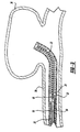
- Figures 3 , 3A and 3B generally illustrate the sequence of placing an embolic device, such as a helical wound coil into an aneurysm 36 which extends from a vessel wall 38. More particularly, Figure 3 illustrates the vascular occlusive embolic device deployment system 10 in the same configuration as shown in Figure 1 after the pusher member and associated embolic device have been inserted into a delivery catheter 35 and advanced into a position for deployment of the embolic device 23, shown as a helical embolic coil, into the aneurysm 36.
- Figure 3A illustrates the deployment device having a configuration similar to Figure 2A with the embolic device 23 being placed within the aneurysm 36 but prior to withdrawal of the detachment member 30.
- the pusher member may be withdrawn thereby withdrawing the embolic device back into the delivery catheter 35 for repositioning to a different location, or alternatively, to remove the embolic coil entirely from the body.
- Figure 3B illustrates the deployment device after the detachment member 30 has been removed from the engagement member 18 thereby releasing the embolic device within the aneurysm 36
- Figure 3C illustrates the deployment device after the pusher member 16 has been withdrawn back into the delivery catheter 35 at the completion of the procedure or alternatively in order to insert a second coil through the delivery catheter 35 and into the same aneurysm.
Landscapes
- Health & Medical Sciences (AREA)
- Surgery (AREA)
- Life Sciences & Earth Sciences (AREA)
- Heart & Thoracic Surgery (AREA)
- Molecular Biology (AREA)
- Vascular Medicine (AREA)
- Engineering & Computer Science (AREA)
- Biomedical Technology (AREA)
- Reproductive Health (AREA)
- Medical Informatics (AREA)
- Nuclear Medicine, Radiotherapy & Molecular Imaging (AREA)
- Animal Behavior & Ethology (AREA)
- General Health & Medical Sciences (AREA)
- Public Health (AREA)
- Veterinary Medicine (AREA)
- Neurosurgery (AREA)
- Surgical Instruments (AREA)
Claims (9)
- Einsatzsystem (10) für eine vasookklusive embolische Einheit zur Verwendung beim Anordnen einer embolischen Einheit (23) an einem vorbestimmten Ort innerhalb eines Gefäßes, das aufweist:einen länglichen, flexiblen Einsatzkatheter (12) mit einem durchgängigen Lumen (14), und mit einem proximalen und einem distalen Ende;ein längliches Schieberelement (16) mit einem durchgängigen Lumen, und mit einem proximalen und einem distalen Ende und verschieblich innerhalb des Lumens (14) des Einsatzkatheters (12) angeordnet;eine embolische Einheit (23), die die Form einer embolischen Spule annimmt, welche an einen Haltering (28) gekoppelt ist;ein längliches Eingriffselement (18), das eine Faser aufweist, welche sich von einer Position proximal dem Schieberelement (16) durch das Lumen in dem Schieberelement (16) zu einer Position distal zu dem Schieberelement (16) erstreckt, die sich durch den Haltering (28) erstreckt, eine Schleife zurück bildet und sich wiederum durch den Haltering (28) zum Anbringen an dem distalen Ende des Schieberelementes (16) erstreckt, um einen Schleifenbereich zu bilden, der eine Öffnung (22) definiert, so dass der Schleifenbereich des Eingriffselements (18) sich durch den Haltering (28) erstreckt; undein längliches Abkoppelelement (30), das sich von einer Position proximal vom proximalen Ende des Schieberelementes (16) durch das Lumen des Schieberelementes (16) und durch die Öffnung (22) des Eingriffselements (18) erstreckt, so dass das Abkoppelelement (30) die embolische Einheit (23) an dem Schieberelement (16) sperrt und so dass, wenn das Abkoppelelement (30) proximal zum distalen Ende des Abkoppelelementes (30) gezogen wird, dieses aus der Öffnung (22) des Eingriffselementes (18) gezogen wird, um somit die embolische Einheit (23) freizugeben.
- Einsatzsystem (10) für eine vasookklusive embolische Einheit nach Anspruch 1, bei dem die embolische Spule (23) ein mittiges Lumen, das sich zwischen dem proximalen und dem distalen Abschnitt der Spule erstreckt, und ein dehnungsfestes Element (25) mit einem ersten und einem zweiten Ende umfasst, wobei das erste Ende des dehnungsfesten Elementes (25) an dem distalen Abschnitt der Spule (23) befestigt ist und das zweite Ende des dehnungsfesten Elementes (23) an dem Haltering (28) befestigt ist.
- Einsatzsystem (10) für eine vasookklusive embolische Einheit nach Anspruch 2, bei dem die Faser des Eingriffselementes (18) aus einem Draht gebildet ist.
- Einsatzsystem (10) für eine vasookklusive embolische Einheit nach Anspruch 1, bei dem die Faser des Eingriffselementes (18) aus einem Polymer gebildet ist.
- Einsatzsystem (10) für eine vasookklusive embolische Einheit nach Anspruch 1, bei dem das Eingriffselement (18) aus einem Nitinol-Draht gebildet ist.
- Einsatzsystem (10) für eine vasookklusive embolische Einheit nach Anspruch 5, bei dem der Schleifenbereich des Eingriffselementes (18) sich derart durch den Haltering (28) der embolischen Einheit (23) erstreckt, dass, wenn sich das Abkoppelelement (16) durch die Öffnung (22) erstreckt, der Haltering (28) der embolischen Einheit (23) auf dem Eingriffselement (18) gesperrt ist, bis das Abkoppelelement (30) aus der Öffnung (22) zurückgezogen ist.
- Einsatzsystem (10) für eine vasookklusive embolische Einheit nach Anspruch 2, bei dem das dehnungsfeste Element (25) aus einem Draht gebildet ist.
- Einsatzsystem (10) für eine vasookklusive embolische Einheit nach Anspruch 2, bei dem das dehnungsfeste Element (25) aus einer Faser gebildet ist.
- Einsatzsystem (10) für eine vasookklusive embolische Einheit nach Anspruch 2, bei dem das erste Ende des dehnungsfesten Elementes (25) an dem distalen Ende der embolischen Spule (23) befestigt ist.
Applications Claiming Priority (1)
| Application Number | Priority Date | Filing Date | Title |
|---|---|---|---|
| US11/171,679 US20060276825A1 (en) | 2005-06-02 | 2005-06-30 | Stretch resistant embolic coil delivery system with mechanical release mechanism |
Publications (2)
| Publication Number | Publication Date |
|---|---|
| EP1738697A1 EP1738697A1 (de) | 2007-01-03 |
| EP1738697B1 true EP1738697B1 (de) | 2010-04-21 |
Family
ID=36930359
Family Applications (1)
| Application Number | Title | Priority Date | Filing Date |
|---|---|---|---|
| EP06253250A Active EP1738697B1 (de) | 2005-06-30 | 2006-06-22 | Mit einem mechanischen Auslösmechanismus versehene Einführvorrichtung für eine ausdehnungswiderstandsfähige Emboliespirale |
Country Status (5)
| Country | Link |
|---|---|
| US (1) | US20060276825A1 (de) |
| EP (1) | EP1738697B1 (de) |
| JP (1) | JP4990571B2 (de) |
| CA (1) | CA2551371A1 (de) |
| DE (1) | DE602006013753D1 (de) |
Cited By (3)
| Publication number | Priority date | Publication date | Assignee | Title |
|---|---|---|---|---|
| US8192480B2 (en) | 2007-12-21 | 2012-06-05 | Microvention, Inc. | System and method of detecting implant detachment |
| US9242070B2 (en) | 2007-12-21 | 2016-01-26 | MicronVention, Inc. | System and method for locating detachment zone of a detachable implant |
| CN106551713A (zh) * | 2007-08-14 | 2017-04-05 | 德国Pfm医用产品有限公司 | 栓塞装置 |
Families Citing this family (60)
| Publication number | Priority date | Publication date | Assignee | Title |
|---|---|---|---|---|
| US7377932B2 (en) * | 2005-06-02 | 2008-05-27 | Cordis Neurovascular, Inc. | Embolic coil delivery system with mechanical release mechanism |
| US7371252B2 (en) * | 2005-06-02 | 2008-05-13 | Cordis Neurovascular, Inc. | Stretch resistant embolic coil delivery system with mechanical release mechanism |
| US7371251B2 (en) * | 2005-06-02 | 2008-05-13 | Cordis Neurovascular, Inc. | Stretch resistant embolic coil delivery system with mechanical release mechanism |
| US7819892B2 (en) * | 2005-06-02 | 2010-10-26 | Codman & Shurtleff, Inc. | Embolic coil delivery system with spring wire release mechanism |
| US7985238B2 (en) * | 2005-06-02 | 2011-07-26 | Codman & Shurtleff, Inc. | Embolic coil delivery system with spring wire release mechanism |
| US7708755B2 (en) * | 2005-06-02 | 2010-05-04 | Codman & Shurtleff Inc. | Stretch resistant embolic coil delivery system with combined mechanical and pressure release mechanism |
| US20060276827A1 (en) * | 2005-06-02 | 2006-12-07 | Vladimir Mitelberg | Stretch resistant embolic coil delivery system with mechanical release mechanism |
| US20060276833A1 (en) * | 2005-06-02 | 2006-12-07 | Keith Balgobin | Stretch resistant embolic coil delivery system with spring assisted release mechanism |
| US7811305B2 (en) * | 2005-06-02 | 2010-10-12 | Codman & Shurtleff, Inc. | Stretch resistant embolic coil delivery system with spring release mechanism |
| US7819891B2 (en) * | 2005-06-02 | 2010-10-26 | Codman & Shurtleff, Inc. | Stretch resistant embolic coil delivery system with spring release mechanism |
| US7708754B2 (en) * | 2005-06-02 | 2010-05-04 | Codman & Shurtleff, Pc | Stretch resistant embolic coil delivery system with mechanical release mechanism |
| US7367987B2 (en) * | 2005-06-02 | 2008-05-06 | Cordis Neurovascular, Inc. | Stretch resistant embolic coil delivery system with mechanical release mechanism |
| US7799052B2 (en) * | 2005-06-02 | 2010-09-21 | Codman & Shurtleff, Inc. | Stretch resistant embolic coil delivery system with mechanical release mechanism |
| US9307996B2 (en) | 2005-12-13 | 2016-04-12 | DePuy Synthes Products, Inc. | Detachment actuator for use with medical device deployment systems |
| US8366720B2 (en) | 2006-07-31 | 2013-02-05 | Codman & Shurtleff, Inc. | Interventional medical device system having an elongation retarding portion and method of using the same |
| US8062325B2 (en) | 2006-07-31 | 2011-11-22 | Codman & Shurtleff, Inc. | Implantable medical device detachment system and methods of using the same |
| US20080306503A1 (en) * | 2006-11-20 | 2008-12-11 | Boston Scientific Scimed, Inc. | Mechanically detachable vaso-occlusive device |
| WO2008064209A1 (en) * | 2006-11-20 | 2008-05-29 | Boston Scientific Scimed, Inc. | Mechanically detachable vaso-occlusive device |
| WO2008085606A1 (en) * | 2006-11-20 | 2008-07-17 | Boston Scientific Scimed, Inc. | Mechanically detachable vaso-occlusive device |
| US8834515B2 (en) * | 2006-11-20 | 2014-09-16 | Boston Scientific Scimed, Inc. | Mechanically detachable vaso-occlusive device |
| US8795316B2 (en) * | 2007-04-25 | 2014-08-05 | DePuy Syntheses Products, LLC | Implantable medical device delivery system with a frangible portion and methods of making and using the same |
| ES2372257T3 (es) * | 2007-12-14 | 2012-01-17 | Micrus Endovascular Llc | Espiral multifilamento para terapias intervencionistas. |
| WO2009146128A1 (en) * | 2008-04-03 | 2009-12-03 | William Cook Europe Aps | Implant release mechanism |
| US8679139B2 (en) * | 2009-04-03 | 2014-03-25 | Cook Medical Technologies Llc | Delivery system for magnetic anastomosis device |
| US9220506B2 (en) | 2010-06-16 | 2015-12-29 | DePuy Synthes Products, Inc. | Occlusive device with stretch resistant member and anchor filament |
| WO2012092351A2 (en) * | 2010-12-30 | 2012-07-05 | Cook Medical Technologies Llc | Delivery of an embolization coil with an attacher |
| WO2012170502A1 (en) * | 2011-06-09 | 2012-12-13 | Cook Medical Technologies Llc | Delivery system for magnetic anastomosis device |
| EP2900150B1 (de) * | 2012-09-29 | 2018-04-18 | Mitralign, Inc. | System zur abgabe von plikationssperren |
| US9629739B2 (en) | 2013-03-13 | 2017-04-25 | DePuy Synthes Products, LLC | Distal capture device for a self-expanding stent |
| US9149278B2 (en) * | 2013-03-13 | 2015-10-06 | DePuy Synthes Products, Inc. | Occlusive device delivery system with mechanical detachment |
| US9918718B2 (en) | 2014-08-08 | 2018-03-20 | DePuy Synthes Products, Inc. | Embolic coil delivery system with retractable mechanical release mechanism |
| WO2016115623A1 (en) * | 2015-01-19 | 2016-07-28 | Jacek Krzyzanowski | Catheter systems and endoscopic systems with reduced backlash |
| US10888331B2 (en) | 2015-02-10 | 2021-01-12 | Boston Scientific Scimed, Inc. | Active release of embolic coils |
| JP7237313B2 (ja) | 2016-07-29 | 2023-03-13 | シャンハイ ワラビー メディカル テクノロジーズ カンパニー インコーポレイテッド | インプラント送達システムおよび方法 |
| US10806462B2 (en) | 2017-12-21 | 2020-10-20 | DePuy Synthes Products, Inc. | Implantable medical device detachment system with split tube and cylindrical coupling |
| CN118902525A (zh) | 2018-07-12 | 2024-11-08 | 上海沃比医疗科技有限公司 | 植入物及其医疗组件 |
| US12114863B2 (en) | 2018-12-05 | 2024-10-15 | Microvention, Inc. | Implant delivery system |
| US11147562B2 (en) | 2018-12-12 | 2021-10-19 | DePuy Synthes Products, Inc. | Systems and methods for embolic implant detachment |
| US11812970B2 (en) | 2019-01-17 | 2023-11-14 | Endostream Medical Ltd. | Vascular-malformation implant system |
| US11253265B2 (en) | 2019-06-18 | 2022-02-22 | DePuy Synthes Products, Inc. | Pull wire detachment for intravascular devices |
| US11426174B2 (en) | 2019-10-03 | 2022-08-30 | DePuy Synthes Products, Inc. | Medical device delivery member with flexible stretch resistant mechanical release |
| US11207494B2 (en) | 2019-07-03 | 2021-12-28 | DePuy Synthes Products, Inc. | Medical device delivery member with flexible stretch resistant distal portion |
| US12376859B2 (en) | 2019-09-17 | 2025-08-05 | DePuy Synthes Products, Inc. | Embolic coil proximal connecting element and stretch resistant fiber |
| US11439403B2 (en) | 2019-09-17 | 2022-09-13 | DePuy Synthes Products, Inc. | Embolic coil proximal connecting element and stretch resistant fiber |
| US11376013B2 (en) | 2019-11-18 | 2022-07-05 | DePuy Synthes Products, Inc. | Implant delivery system with braid cup formation |
| US11457922B2 (en) | 2020-01-22 | 2022-10-04 | DePuy Synthes Products, Inc. | Medical device delivery member with flexible stretch resistant distal portion |
| US11432822B2 (en) | 2020-02-14 | 2022-09-06 | DePuy Synthes Products, Inc. | Intravascular implant deployment system |
| US11951026B2 (en) | 2020-06-30 | 2024-04-09 | DePuy Synthes Products, Inc. | Implantable medical device detachment system with flexible braid section |
| US11998213B2 (en) | 2021-07-14 | 2024-06-04 | DePuy Synthes Products, Inc. | Implant delivery with modified detachment feature and pull wire engagement |
| US11844490B2 (en) | 2021-12-30 | 2023-12-19 | DePuy Synthes Products, Inc. | Suture linkage for inhibiting premature embolic implant deployment |
| US11937824B2 (en) | 2021-12-30 | 2024-03-26 | DePuy Synthes Products, Inc. | Implant detachment systems with a modified pull wire |
| US12508032B2 (en) | 2021-12-31 | 2025-12-30 | DePuy Synthes Products, Inc. | Medical device delivery systems with twisting loop wires |
| US12011171B2 (en) | 2022-01-06 | 2024-06-18 | DePuy Synthes Products, Inc. | Systems and methods for inhibiting premature embolic implant deployment |
| US12471924B2 (en) | 2022-03-02 | 2025-11-18 | DePuy Synthes Products, Inc. | Flexible feature for embolic implant deployment |
| US11937825B2 (en) | 2022-03-02 | 2024-03-26 | DePuy Synthes Products, Inc. | Hook wire for preventing premature embolic implant detachment |
| US12137915B2 (en) | 2022-03-03 | 2024-11-12 | DePuy Synthes Products, Inc. | Elongating wires for inhibiting premature implant detachment |
| US11937826B2 (en) | 2022-03-14 | 2024-03-26 | DePuy Synthes Products, Inc. | Proximal link wire for preventing premature implant detachment |
| US12402886B2 (en) | 2022-06-23 | 2025-09-02 | DePuy Synthes Products, Inc. | Detachment indicator for implant deployment |
| US12446888B2 (en) | 2022-08-26 | 2025-10-21 | Depuy Synthes Products, Inc | Twister implant detachment mechanism |
| US12396730B2 (en) | 2022-09-28 | 2025-08-26 | DePuy Synthes Products, Inc. | Braided implant with detachment mechanism |
Family Cites Families (49)
| Publication number | Priority date | Publication date | Assignee | Title |
|---|---|---|---|---|
| US5304197A (en) * | 1988-10-04 | 1994-04-19 | Cordis Corporation | Balloons for medical devices and fabrication thereof |
| US5354295A (en) * | 1990-03-13 | 1994-10-11 | Target Therapeutics, Inc. | In an endovascular electrolytically detachable wire and tip for the formation of thrombus in arteries, veins, aneurysms, vascular malformations and arteriovenous fistulas |
| US5122136A (en) | 1990-03-13 | 1992-06-16 | The Regents Of The University Of California | Endovascular electrolytically detachable guidewire tip for the electroformation of thrombus in arteries, veins, aneurysms, vascular malformations and arteriovenous fistulas |
| US5108407A (en) * | 1990-06-08 | 1992-04-28 | Rush-Presbyterian St. Luke's Medical Center | Method and apparatus for placement of an embolic coil |
| US5122138A (en) * | 1990-11-28 | 1992-06-16 | Manwaring Kim H | Tissue vaporizing accessory and method for an endoscope |
| US5217484A (en) * | 1991-06-07 | 1993-06-08 | Marks Michael P | Retractable-wire catheter device and method |
| US5263964A (en) * | 1992-05-06 | 1993-11-23 | Coil Partners Ltd. | Coaxial traction detachment apparatus and method |
| US5250071A (en) * | 1992-09-22 | 1993-10-05 | Target Therapeutics, Inc. | Detachable embolic coil assembly using interlocking clasps and method of use |
| US5350397A (en) * | 1992-11-13 | 1994-09-27 | Target Therapeutics, Inc. | Axially detachable embolic coil assembly |
| US5382259A (en) * | 1992-10-26 | 1995-01-17 | Target Therapeutics, Inc. | Vasoocclusion coil with attached tubular woven or braided fibrous covering |
| US5334210A (en) * | 1993-04-09 | 1994-08-02 | Cook Incorporated | Vascular occlusion assembly |
| US5925059A (en) * | 1993-04-19 | 1999-07-20 | Target Therapeutics, Inc. | Detachable embolic coil assembly |
| US5800453A (en) * | 1993-04-19 | 1998-09-01 | Target Therapeutics, Inc. | Detachable embolic coil assembly using interlocking hooks and slots |
| US5814062A (en) * | 1994-12-22 | 1998-09-29 | Target Therapeutics, Inc. | Implant delivery assembly with expandable coupling/decoupling mechanism |
| EP0805656B1 (de) * | 1995-01-27 | 2004-05-06 | SciMed Life Systems, Inc. | Embolisationssystem |
| US6013084A (en) * | 1995-06-30 | 2000-01-11 | Target Therapeutics, Inc. | Stretch resistant vaso-occlusive coils (II) |
| US5853418A (en) * | 1995-06-30 | 1998-12-29 | Target Therapeutics, Inc. | Stretch resistant vaso-occlusive coils (II) |
| US5582619A (en) * | 1995-06-30 | 1996-12-10 | Target Therapeutics, Inc. | Stretch resistant vaso-occlusive coils |
| US5601600A (en) * | 1995-09-08 | 1997-02-11 | Conceptus, Inc. | Endoluminal coil delivery system having a mechanical release mechanism |
| US5895391A (en) * | 1996-09-27 | 1999-04-20 | Target Therapeutics, Inc. | Ball lock joint and introducer for vaso-occlusive member |
| JPH1099338A (ja) * | 1996-09-30 | 1998-04-21 | Piolax Inc | 管状器官内部に留置される栓体の回収具 |
| US5733329A (en) * | 1996-12-30 | 1998-03-31 | Target Therapeutics, Inc. | Vaso-occlusive coil with conical end |
| US6203547B1 (en) * | 1997-12-19 | 2001-03-20 | Target Therapeutics, Inc. | Vaso-occlusion apparatus having a manipulable mechanical detachment joint and a method for using the apparatus |
| US6113622A (en) | 1998-03-10 | 2000-09-05 | Cordis Corporation | Embolic coil hydraulic deployment system |
| US6478773B1 (en) * | 1998-12-21 | 2002-11-12 | Micrus Corporation | Apparatus for deployment of micro-coil using a catheter |
| US7044134B2 (en) * | 1999-11-08 | 2006-05-16 | Ev3 Sunnyvale, Inc | Method of implanting a device in the left atrial appendage |
| US7713282B2 (en) * | 1998-11-06 | 2010-05-11 | Atritech, Inc. | Detachable atrial appendage occlusion balloon |
| US6835185B2 (en) * | 1998-12-21 | 2004-12-28 | Micrus Corporation | Intravascular device deployment mechanism incorporating mechanical detachment |
| US6113822A (en) * | 1998-12-23 | 2000-09-05 | General Electric Company | Polyolefins as nucleating agent for foamed engineering polymers |
| US6193726B1 (en) * | 1999-01-15 | 2001-02-27 | Heartstent Corporation | Insertion tool for transmyocardial implant |
| US6402781B1 (en) * | 2000-01-31 | 2002-06-11 | Mitralife | Percutaneous mitral annuloplasty and cardiac reinforcement |
| JP2004502051A (ja) * | 2000-06-29 | 2004-01-22 | ジョンソン・アンド・ジョンソン・コンシューマー・カンパニーズ・インコーポレイテッド | 支持体へのパウダーの静電浸透 |
| US6793673B2 (en) * | 2002-12-26 | 2004-09-21 | Cardiac Dimensions, Inc. | System and method to effect mitral valve annulus of a heart |
| US7608058B2 (en) * | 2002-07-23 | 2009-10-27 | Micrus Corporation | Stretch resistant therapeutic device |
| US7316708B2 (en) * | 2002-12-05 | 2008-01-08 | Cardiac Dimensions, Inc. | Medical device delivery system |
| US6902572B2 (en) * | 2003-04-02 | 2005-06-07 | Scimed Life Systems, Inc. | Anchoring mechanisms for intravascular devices |
| US7819892B2 (en) * | 2005-06-02 | 2010-10-26 | Codman & Shurtleff, Inc. | Embolic coil delivery system with spring wire release mechanism |
| US7799052B2 (en) * | 2005-06-02 | 2010-09-21 | Codman & Shurtleff, Inc. | Stretch resistant embolic coil delivery system with mechanical release mechanism |
| US20060276830A1 (en) * | 2005-06-02 | 2006-12-07 | Keith Balgobin | Stretch resistant embolic coil delivery system with mechanical release mechanism |
| US20060276827A1 (en) * | 2005-06-02 | 2006-12-07 | Vladimir Mitelberg | Stretch resistant embolic coil delivery system with mechanical release mechanism |
| US7811305B2 (en) * | 2005-06-02 | 2010-10-12 | Codman & Shurtleff, Inc. | Stretch resistant embolic coil delivery system with spring release mechanism |
| US7371251B2 (en) * | 2005-06-02 | 2008-05-13 | Cordis Neurovascular, Inc. | Stretch resistant embolic coil delivery system with mechanical release mechanism |
| US20060276833A1 (en) * | 2005-06-02 | 2006-12-07 | Keith Balgobin | Stretch resistant embolic coil delivery system with spring assisted release mechanism |
| US7371252B2 (en) * | 2005-06-02 | 2008-05-13 | Cordis Neurovascular, Inc. | Stretch resistant embolic coil delivery system with mechanical release mechanism |
| US7819891B2 (en) * | 2005-06-02 | 2010-10-26 | Codman & Shurtleff, Inc. | Stretch resistant embolic coil delivery system with spring release mechanism |
| US7367987B2 (en) * | 2005-06-02 | 2008-05-06 | Cordis Neurovascular, Inc. | Stretch resistant embolic coil delivery system with mechanical release mechanism |
| US7985238B2 (en) * | 2005-06-02 | 2011-07-26 | Codman & Shurtleff, Inc. | Embolic coil delivery system with spring wire release mechanism |
| US7377932B2 (en) * | 2005-06-02 | 2008-05-27 | Cordis Neurovascular, Inc. | Embolic coil delivery system with mechanical release mechanism |
| EP1738698A2 (de) * | 2005-06-30 | 2007-01-03 | Cordis Neurovascular, Inc. | Einführvorrichtung für eine Emboliespirale |
-
2005
- 2005-06-30 US US11/171,679 patent/US20060276825A1/en not_active Abandoned
-
2006
- 2006-06-22 DE DE602006013753T patent/DE602006013753D1/de active Active
- 2006-06-22 EP EP06253250A patent/EP1738697B1/de active Active
- 2006-06-29 CA CA002551371A patent/CA2551371A1/en not_active Abandoned
- 2006-06-29 JP JP2006180019A patent/JP4990571B2/ja active Active
Cited By (5)
| Publication number | Priority date | Publication date | Assignee | Title |
|---|---|---|---|---|
| CN106551713A (zh) * | 2007-08-14 | 2017-04-05 | 德国Pfm医用产品有限公司 | 栓塞装置 |
| US8192480B2 (en) | 2007-12-21 | 2012-06-05 | Microvention, Inc. | System and method of detecting implant detachment |
| US8460332B2 (en) | 2007-12-21 | 2013-06-11 | Microvention, Inc. | System and method of detecting implant detachment |
| US9242070B2 (en) | 2007-12-21 | 2016-01-26 | MicronVention, Inc. | System and method for locating detachment zone of a detachable implant |
| US10299755B2 (en) | 2007-12-21 | 2019-05-28 | Microvention, Inc. | System and method for locating detachment zone of a detachable implant |
Also Published As
| Publication number | Publication date |
|---|---|
| CA2551371A1 (en) | 2006-12-30 |
| JP2007007419A (ja) | 2007-01-18 |
| EP1738697A1 (de) | 2007-01-03 |
| JP4990571B2 (ja) | 2012-08-01 |
| US20060276825A1 (en) | 2006-12-07 |
| DE602006013753D1 (de) | 2010-06-02 |
Similar Documents
| Publication | Publication Date | Title |
|---|---|---|
| EP1728478B1 (de) | Mit einem mechanischen Auslösmechanismus versehene Einführvorrichtung für eine ausdehnungswiderstandsfähige Emboliespirale | |
| EP1738696B1 (de) | Einführvorrichtung für eine ausdehnungswiderstandsfähige Emboliespiralfeder mit einem mechanischen Auslösemechanismus | |
| EP1728477B1 (de) | Mit einem mechanischen Auslösmechanismus versehene Einführvorrichtung für eine Emboliespirale | |
| US7371252B2 (en) | Stretch resistant embolic coil delivery system with mechanical release mechanism | |
| EP1795133B1 (de) | Mit einem mechanischen Auslösmechanismus versehene Einführvorrichtung für eine ausdehnungswiderstandsfähige Emboliespirale | |
| CA2571004C (en) | Stretch resistant embolic coil delivery system with mechanical release mechanism | |
| US7799052B2 (en) | Stretch resistant embolic coil delivery system with mechanical release mechanism | |
| US7811305B2 (en) | Stretch resistant embolic coil delivery system with spring release mechanism | |
| US7819891B2 (en) | Stretch resistant embolic coil delivery system with spring release mechanism | |
| US7901444B2 (en) | Embolic coil delivery system with mechanical release mechanism | |
| EP1738697A1 (de) | Mit einem mechanischen Auslösmechanismus versehene Einführvorrichtung für eine ausdehnungswiderstandsfähige Emboliespirale | |
| US7985238B2 (en) | Embolic coil delivery system with spring wire release mechanism | |
| EP1621148B1 (de) | Einführvorrichtung für Emboliespirale mit Bandlösesystem | |
| US7819892B2 (en) | Embolic coil delivery system with spring wire release mechanism | |
| EP1621150B1 (de) | Ablagesystem für Embolievorrichtung mit zurückziehbarer teilweise fasergewickelter Auslösung | |
| EP1738698A2 (de) | Einführvorrichtung für eine Emboliespirale | |
| US20060276833A1 (en) | Stretch resistant embolic coil delivery system with spring assisted release mechanism |
Legal Events
| Date | Code | Title | Description |
|---|---|---|---|
| PUAI | Public reference made under article 153(3) epc to a published international application that has entered the european phase |
Free format text: ORIGINAL CODE: 0009012 |
|
| AK | Designated contracting states |
Kind code of ref document: A1 Designated state(s): AT BE BG CH CY CZ DE DK EE ES FI FR GB GR HU IE IS IT LI LT LU LV MC NL PL PT RO SE SI SK TR |
|
| AX | Request for extension of the european patent |
Extension state: AL BA HR MK YU |
|
| 17P | Request for examination filed |
Effective date: 20070605 |
|
| 17Q | First examination report despatched |
Effective date: 20070719 |
|
| AKX | Designation fees paid |
Designated state(s): DE FR GB NL |
|
| GRAP | Despatch of communication of intention to grant a patent |
Free format text: ORIGINAL CODE: EPIDOSNIGR1 |
|
| GRAS | Grant fee paid |
Free format text: ORIGINAL CODE: EPIDOSNIGR3 |
|
| GRAA | (expected) grant |
Free format text: ORIGINAL CODE: 0009210 |
|
| RAP1 | Party data changed (applicant data changed or rights of an application transferred) |
Owner name: CODMAN & SHURTLEFF, INC. |
|
| AK | Designated contracting states |
Kind code of ref document: B1 Designated state(s): DE FR GB NL |
|
| REG | Reference to a national code |
Ref country code: GB Ref legal event code: FG4D |
|
| REF | Corresponds to: |
Ref document number: 602006013753 Country of ref document: DE Date of ref document: 20100602 Kind code of ref document: P |
|
| REG | Reference to a national code |
Ref country code: NL Ref legal event code: T3 |
|
| PLBE | No opposition filed within time limit |
Free format text: ORIGINAL CODE: 0009261 |
|
| STAA | Information on the status of an ep patent application or granted ep patent |
Free format text: STATUS: NO OPPOSITION FILED WITHIN TIME LIMIT |
|
| 26N | No opposition filed |
Effective date: 20110124 |
|
| REG | Reference to a national code |
Ref country code: FR Ref legal event code: CA Effective date: 20111011 |
|
| REG | Reference to a national code |
Ref country code: FR Ref legal event code: PLFP Year of fee payment: 11 |
|
| REG | Reference to a national code |
Ref country code: FR Ref legal event code: PLFP Year of fee payment: 12 |
|
| REG | Reference to a national code |
Ref country code: FR Ref legal event code: PLFP Year of fee payment: 13 |
|
| PGFP | Annual fee paid to national office [announced via postgrant information from national office to epo] |
Ref country code: NL Payment date: 20190612 Year of fee payment: 14 |
|
| REG | Reference to a national code |
Ref country code: NL Ref legal event code: MM Effective date: 20200701 |
|
| PG25 | Lapsed in a contracting state [announced via postgrant information from national office to epo] |
Ref country code: NL Free format text: LAPSE BECAUSE OF NON-PAYMENT OF DUE FEES Effective date: 20200701 |
|
| PGFP | Annual fee paid to national office [announced via postgrant information from national office to epo] |
Ref country code: DE Payment date: 20250429 Year of fee payment: 20 |
|
| PGFP | Annual fee paid to national office [announced via postgrant information from national office to epo] |
Ref country code: GB Payment date: 20250501 Year of fee payment: 20 |
|
| PGFP | Annual fee paid to national office [announced via postgrant information from national office to epo] |
Ref country code: FR Payment date: 20250508 Year of fee payment: 20 |