EP1738882A2 - Dispositif et méthode pour sécuriser un appareil ayant des parties se déplaçant dans l'espace - Google Patents
Dispositif et méthode pour sécuriser un appareil ayant des parties se déplaçant dans l'espace Download PDFInfo
- Publication number
- EP1738882A2 EP1738882A2 EP06015847A EP06015847A EP1738882A2 EP 1738882 A2 EP1738882 A2 EP 1738882A2 EP 06015847 A EP06015847 A EP 06015847A EP 06015847 A EP06015847 A EP 06015847A EP 1738882 A2 EP1738882 A2 EP 1738882A2
- Authority
- EP
- European Patent Office
- Prior art keywords
- sensor system
- tactile
- parts
- control signal
- safety
- Prior art date
- Legal status (The legal status is an assumption and is not a legal conclusion. Google has not performed a legal analysis and makes no representation as to the accuracy of the status listed.)
- Withdrawn
Links
- 238000000034 method Methods 0.000 title claims abstract description 11
- 230000003287 optical effect Effects 0.000 claims abstract description 13
- 238000012544 monitoring process Methods 0.000 claims description 19
- 238000013016 damping Methods 0.000 claims description 8
- 239000000463 material Substances 0.000 claims description 8
- 230000001960 triggered effect Effects 0.000 claims description 5
- 238000005259 measurement Methods 0.000 claims description 4
- 230000009471 action Effects 0.000 claims description 3
- 230000000694 effects Effects 0.000 claims description 3
- 230000000977 initiatory effect Effects 0.000 claims description 2
- 230000005670 electromagnetic radiation Effects 0.000 claims 1
- 238000013459 approach Methods 0.000 description 6
- 238000001514 detection method Methods 0.000 description 6
- 230000035945 sensitivity Effects 0.000 description 5
- 239000012636 effector Substances 0.000 description 3
- 239000003990 capacitor Substances 0.000 description 2
- 230000008859 change Effects 0.000 description 2
- 239000011248 coating agent Substances 0.000 description 2
- 238000000576 coating method Methods 0.000 description 2
- 238000013178 mathematical model Methods 0.000 description 2
- 239000004033 plastic Substances 0.000 description 2
- 229920003023 plastic Polymers 0.000 description 2
- 230000008569 process Effects 0.000 description 2
- 230000001681 protective effect Effects 0.000 description 2
- 238000012360 testing method Methods 0.000 description 2
- XLYOFNOQVPJJNP-UHFFFAOYSA-N water Substances O XLYOFNOQVPJJNP-UHFFFAOYSA-N 0.000 description 2
- 229920005830 Polyurethane Foam Polymers 0.000 description 1
- 230000008901 benefit Effects 0.000 description 1
- 238000004364 calculation method Methods 0.000 description 1
- 239000004020 conductor Substances 0.000 description 1
- 125000004122 cyclic group Chemical group 0.000 description 1
- 230000001351 cycling effect Effects 0.000 description 1
- 238000013461 design Methods 0.000 description 1
- 238000010586 diagram Methods 0.000 description 1
- 230000005684 electric field Effects 0.000 description 1
- 239000006260 foam Substances 0.000 description 1
- 231100001261 hazardous Toxicity 0.000 description 1
- 238000007689 inspection Methods 0.000 description 1
- 238000004519 manufacturing process Methods 0.000 description 1
- 239000002184 metal Substances 0.000 description 1
- 230000002093 peripheral effect Effects 0.000 description 1
- 230000000704 physical effect Effects 0.000 description 1
- 239000011496 polyurethane foam Substances 0.000 description 1
- 230000005855 radiation Effects 0.000 description 1
- 230000001105 regulatory effect Effects 0.000 description 1
- 230000004044 response Effects 0.000 description 1
- 238000000926 separation method Methods 0.000 description 1
- 230000035939 shock Effects 0.000 description 1
- 238000012549 training Methods 0.000 description 1
- 239000003190 viscoelastic substance Substances 0.000 description 1
Images

Classifications
-
- B—PERFORMING OPERATIONS; TRANSPORTING
- B25—HAND TOOLS; PORTABLE POWER-DRIVEN TOOLS; MANIPULATORS
- B25J—MANIPULATORS; CHAMBERS PROVIDED WITH MANIPULATION DEVICES
- B25J13/00—Controls for manipulators
- B25J13/08—Controls for manipulators by means of sensing devices, e.g. viewing or touching devices
- B25J13/086—Proximity sensors
-
- B—PERFORMING OPERATIONS; TRANSPORTING
- B25—HAND TOOLS; PORTABLE POWER-DRIVEN TOOLS; MANIPULATORS
- B25J—MANIPULATORS; CHAMBERS PROVIDED WITH MANIPULATION DEVICES
- B25J13/00—Controls for manipulators
- B25J13/08—Controls for manipulators by means of sensing devices, e.g. viewing or touching devices
- B25J13/081—Touching devices, e.g. pressure-sensitive
- B25J13/084—Tactile sensors
-
- B—PERFORMING OPERATIONS; TRANSPORTING
- B25—HAND TOOLS; PORTABLE POWER-DRIVEN TOOLS; MANIPULATORS
- B25J—MANIPULATORS; CHAMBERS PROVIDED WITH MANIPULATION DEVICES
- B25J19/00—Accessories fitted to manipulators, e.g. for monitoring, for viewing; Safety devices combined with or specially adapted for use in connection with manipulators
- B25J19/0091—Shock absorbers
-
- B—PERFORMING OPERATIONS; TRANSPORTING
- B25—HAND TOOLS; PORTABLE POWER-DRIVEN TOOLS; MANIPULATORS
- B25J—MANIPULATORS; CHAMBERS PROVIDED WITH MANIPULATION DEVICES
- B25J19/00—Accessories fitted to manipulators, e.g. for monitoring, for viewing; Safety devices combined with or specially adapted for use in connection with manipulators
- B25J19/02—Sensing devices
- B25J19/027—Electromagnetic sensing devices
-
- B—PERFORMING OPERATIONS; TRANSPORTING
- B25—HAND TOOLS; PORTABLE POWER-DRIVEN TOOLS; MANIPULATORS
- B25J—MANIPULATORS; CHAMBERS PROVIDED WITH MANIPULATION DEVICES
- B25J19/00—Accessories fitted to manipulators, e.g. for monitoring, for viewing; Safety devices combined with or specially adapted for use in connection with manipulators
- B25J19/06—Safety devices
- B25J19/063—Safety devices working only upon contact with an outside object
-
- F—MECHANICAL ENGINEERING; LIGHTING; HEATING; WEAPONS; BLASTING
- F16—ENGINEERING ELEMENTS AND UNITS; GENERAL MEASURES FOR PRODUCING AND MAINTAINING EFFECTIVE FUNCTIONING OF MACHINES OR INSTALLATIONS; THERMAL INSULATION IN GENERAL
- F16P—SAFETY DEVICES IN GENERAL; SAFETY DEVICES FOR PRESSES
- F16P3/00—Safety devices acting in conjunction with the control or operation of a machine; Control arrangements requiring the simultaneous use of two or more parts of the body
- F16P3/12—Safety devices acting in conjunction with the control or operation of a machine; Control arrangements requiring the simultaneous use of two or more parts of the body with means, e.g. feelers, which in case of the presence of a body part of a person in or near the danger zone influence the control or operation of the machine
-
- F—MECHANICAL ENGINEERING; LIGHTING; HEATING; WEAPONS; BLASTING
- F16—ENGINEERING ELEMENTS AND UNITS; GENERAL MEASURES FOR PRODUCING AND MAINTAINING EFFECTIVE FUNCTIONING OF MACHINES OR INSTALLATIONS; THERMAL INSULATION IN GENERAL
- F16P—SAFETY DEVICES IN GENERAL; SAFETY DEVICES FOR PRESSES
- F16P3/00—Safety devices acting in conjunction with the control or operation of a machine; Control arrangements requiring the simultaneous use of two or more parts of the body
- F16P3/12—Safety devices acting in conjunction with the control or operation of a machine; Control arrangements requiring the simultaneous use of two or more parts of the body with means, e.g. feelers, which in case of the presence of a body part of a person in or near the danger zone influence the control or operation of the machine
- F16P3/14—Safety devices acting in conjunction with the control or operation of a machine; Control arrangements requiring the simultaneous use of two or more parts of the body with means, e.g. feelers, which in case of the presence of a body part of a person in or near the danger zone influence the control or operation of the machine the means being photocells or other devices sensitive without mechanical contact
- F16P3/144—Safety devices acting in conjunction with the control or operation of a machine; Control arrangements requiring the simultaneous use of two or more parts of the body with means, e.g. feelers, which in case of the presence of a body part of a person in or near the danger zone influence the control or operation of the machine the means being photocells or other devices sensitive without mechanical contact using light grids
-
- F—MECHANICAL ENGINEERING; LIGHTING; HEATING; WEAPONS; BLASTING
- F16—ENGINEERING ELEMENTS AND UNITS; GENERAL MEASURES FOR PRODUCING AND MAINTAINING EFFECTIVE FUNCTIONING OF MACHINES OR INSTALLATIONS; THERMAL INSULATION IN GENERAL
- F16P—SAFETY DEVICES IN GENERAL; SAFETY DEVICES FOR PRESSES
- F16P3/00—Safety devices acting in conjunction with the control or operation of a machine; Control arrangements requiring the simultaneous use of two or more parts of the body
- F16P3/12—Safety devices acting in conjunction with the control or operation of a machine; Control arrangements requiring the simultaneous use of two or more parts of the body with means, e.g. feelers, which in case of the presence of a body part of a person in or near the danger zone influence the control or operation of the machine
- F16P3/14—Safety devices acting in conjunction with the control or operation of a machine; Control arrangements requiring the simultaneous use of two or more parts of the body with means, e.g. feelers, which in case of the presence of a body part of a person in or near the danger zone influence the control or operation of the machine the means being photocells or other devices sensitive without mechanical contact
- F16P3/148—Safety devices acting in conjunction with the control or operation of a machine; Control arrangements requiring the simultaneous use of two or more parts of the body with means, e.g. feelers, which in case of the presence of a body part of a person in or near the danger zone influence the control or operation of the machine the means being photocells or other devices sensitive without mechanical contact using capacitive technology
Definitions
- the invention relates to a safety device for devices with freely movable in space parts, in particular for handling equipment, such as industrial robots or driverless transport devices, with switching means that cause a collision of the moving parts with persons or objects a control signal, and a method for securing devices with in Space movable parts, in particular for handling equipment, such as industrial robots or driverless transport devices, with switching means that cause a collision of the moving parts with persons or objects, a control signal.
- handling devices in particular industrial robots
- safety devices for the operation of devices with freely movable parts, in particular for industrial robots, so far a strict separation of the working spaces of Man and machine on.
- usually separating guards such as fences are used.
- movable guards such as protective doors or flaps
- non-guards such as laser scanners, safety mats, according to protection category 3 or 4, DIN EN 954-1
- the aforementioned switching mats use the physical effects that occur in the case of distortion of an optical waveguide.
- a corresponding device is from the DE 44 28 650 A1 known.
- the modal distribution of the radiation field changes even at low compressive stress, so that a suitably arranged light detector can measure pressure forces with high sensitivity.
- the CH 682 351 A5 / EP 0 264 350 describes one of the many conventional devices used to protect the work area of equipment. It discloses a process-controlled system with associated monitoring circuit and a safety circuit, which in particular has an access light and a door, by means of which the access to the vicinity of the robot is regulated or constantly monitored, so that in the event that an operator stays in the vicinity, only a standstill of the system or a creep operation is possible.
- the EP 0 725 710 B1 describes a further variant in which an operator controls a movable device in space by the departure of a miniature model of the object to be processed with a miniature model of the device.
- a safety zone around the device is defined by the fact that the miniature model of the device has a slightly larger scale than the object model. Collisions between the (real) device and the object should be excluded "with absolute certainty”. Additional safety devices that could detect or prevent any collisions are not disclosed.
- the EP 0 012 383 discloses a system with moving parts, which is arranged with an area between two electrode layers on the moving parts of the system, under pressure pressure electrically conductive plastic layer.
- a deformable layer can be arranged between the sensor system formed therefrom and the plant components.
- the EP 0 689 903 shows a robot with a coating of visco-elastic material, wherein pressure sensors are arranged on the surface or under this coating for detecting collisions.
- a capacitive sensor system of the DE 40 06 119 C2 known.
- This document relates to a capacitive transducer system with an externally modulated capacitor having an active electrode, a ground electrode and between the active electrode and the ground electrode arranged shielding electrode which is at the same electrical potential as the active electrode.
- the WO 86/02506 relates to a capacitive proximity sensor for use with elevator doors. This document also discloses a capacitive sensor with three-electrode arrangement, which also has a spatially directed detection sensitivity.
- Such capacitive sensors measure the capacitance change caused by the approach of an object in the electric field of the capacitor formed by the sensor.
- Capacitive sensors detect, in addition to all electrically highly conductive materials only those materials whose permittivity is sufficiently large.
- a capacitive sensor system can not detect all types of materials is disadvantageous, especially for use as a safety device in fast moving devices with massive, freely moving parts.
- the invention has for its object to provide a safety device for the operation of devices with freely movable parts in space, which allows the safe operation of such devices without complex peripheral devices and also ensures that collisions between device parts and people or objects early and reliably detected In addition to avoiding planning and production costs, a significantly reduced space requirement for such systems results, so that people and machines can share workspaces in the future.
- the invention provides in a generic safety device both at least one tactile sensor system of moving parts of the device and at least one non-contact sensor system.
- the object is further achieved by a method in which when approaching a movable part of the device to an object or a person both a non-contact sensor system and a tactile sensor system responds.
- both a non-contact and a tactile sensor system are installed on the moving parts of a device.
- the tactile system responds when touched by a person or object.
- the inventive tactile optical sensor system with optical waveguides can be easily adapted to the non-smooth structures and surfaces in a robot. In addition, this gives a security against electromagnetic interference, which can not lead to false tripping.
- the tactile sensor system according to the invention which is designed in the form of a tactile skin, can be arranged directly on the housing of the device. To exclude damage due to mechanical effects, it is provided according to a preferred embodiment to protect the tactile sensor system to the outside by a shock-absorbing partially elastic layer.
- the tactile sensor system outside the housing surrounding the shock absorbing partial elastic layer, whereby a greater proximity of the sensor to the object to be detected is achieved.
- a further embodiment of the teaching according to the invention therefore provides that the layer surrounding the housing parts or the housing parts and the tactile sensor system is resilient and damping.
- the layer By the springs you gain stopping distance, so it does not come immediately after the first touch to a hard blow. If the layer has damping properties, kinetic energy is reduced and the acting force remains limited over a longer path. This allows the user to drive the device faster.
- it is provided to form the shock-absorbing partially elastic layer of a material with a mechanical efficiency of between 0.5 and 0.7, in particular with a mechanical efficiency of 0.6.
- a flexible polyurethane foam is used for this purpose, which absorbs large parts of the resulting kinetic energy and converts it into heat.
- the safety device according to the invention is characterized in particular by its high detection sensitivity, since it is provided in an advantageous embodiment of the invention that the tactile sensor system formed of optical waveguides already from a force of 0.5 to 1.5 N, in particular 1 N responds.
- the non-contact sensor system can thus create a redundant overall system that meets the requirements of industrial robots, for example of category 3/4 according to the European standard DIN EN 954-1 is sufficient.
- the safety device comprises another sensor system independent of the tactile sensor system, by means of which people and other objects with high permittivity numbers can be detected without contact and by which a safety-relevant control signal is already triggered upon approaching - that is to say before a collision.
- This further diverse or independent sensor system is, in an advantageous embodiment, a capacitive sensor system with at least one sensor element formed from two or more electrodes.
- three-electrode systems can be used which have a grounded electrode, a sensor electrode and a screen electrode arranged between the latter.
- sensor ranges in the centimeter range are achieved.
- the shielding electrode in particular allows a directivity of the capacitive sensor. It reduces the stray capacitances towards the housing and significantly improves the sensitivity to approach. This additional system makes the detection of danger largely redundant.
- the capacitive system can also detect areas in which the tactile system may not reliably respond. In addition, approaches can be captured in advance.
- Water has an 81 times increased permittivity ⁇ r compared to dry air. Since the human consists of more than two-thirds of its mass of water, it can be detected reliably - in particular by surface electrodes - up to a distance of more than 10 cm.
- the capacitive sensor system formed from a plurality of sensor elements may comprise a plurality of planar sensor elements having corresponding surface electrodes. These sensor elements are advantageously subdivided in a sector-shaped manner, which makes it possible to hide sectors individually or in groups as soon as they are within an allowable position provided by the control. This makes it possible to avoid an undesired response of the capacitive sensor system for those cases in which safety-relevant components legally move towards one another.
- dividing the capacitive sensor system into sectors has the further advantage that it results in a greater number of electrodes, each having a smaller surface area than the overall system. As the relative change in capacitance increases as one and the same object approach the smaller the electrode surface, the sensor becomes more sensitive, especially to the approach of small objects.
- the electrodes of the capacitive sensor system are arranged asymmetrically, with crimped shielding electrodes being used in an extremely advantageous embodiment.
- the capacitive sensor system is provided outside the housing. This can be done either directly on the outer surface of the housing or even on the cushioning foam layer. As a result, in addition to a greater proximity to the object to be detected, in particular a greater distance to internal sources of interference, e.g. to the power electronics of the motors, reach.
- the housing is advantageously made of a material with a low permittivity, which can be done in particular by the use of plastic.
- the arrangement of the tactile sensor system, the capacitive sensor system and the shock-absorbing partially elastic layer takes place in the form of each plane-parallel to the housing layers whose sequence can vary as desired with respect to the housing.
- the two independent sensor systems ie the tactile sensor system and the capacitive sensor system, engage directly in the emergency stop circuit of the device.
- the possibly caused control signals of the two sensor systems are preferably linked in the sense of a logical OR operation, ie it is a safety-relevant action - for example, a shutdown of the device, initiating one of the collision movement opposite movement sequence and / or triggering an optical and / or audible alarm - caused when one of the two OR both control signals were effected.
- An extremely advantageous embodiment of the invention provides that all sensor surfaces themselves by cycling a safety program, in particular by approaching a test specimen in the course of a control drive, control themselves.
- a third system designed as a motor current monitoring system for monitoring motor currents in the electric motors present in the moving parts moving device.
- a motor current monitoring system registers the increase of the motor currents above the value to be expected in the collision-free normal case and in this case triggers a control signal by which the dangerous movement is stopped or a countermovement is initiated.
- control signals of these two sensor systems in the sense of a logical OR operation are linked together.
- this separate redundant system it is further provided to check the safety functions of this separate redundant system by a machine program, wherein the device is driven against a resistance. As long as the motor current monitoring system and the force-moment sensor detect independently exceeding the standard values, the overall system is still in order.
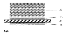
- FIG. 1 shows a schematic sectional view of an example of the possible arrangement of the sensor and damping layers of the safety device according to the invention with respect to the housing or with respect to housing parts of the device.
- a housing part 1.1 of a movable part 2.2 of the device 2.1 such as a robot arm (part) of a robot (device), is shown as a (local) flat plate.
- a tactile sensor system 1.2 is arranged above the housing part 1.1, i. outside the device 2.1, which is protected in the embodiment shown to the outside by a shock-absorbing partially elastic layer 1.3.
- a capacitive sensor system 1.4 is provided below the housing part 1.1, wherein the arrangement of the tactile sensor system 1.2, the damping layer 1.3 and the capacitive sensor system 1.4 takes place in respect to the housing part 1.1 plane-parallel superimposed layers.
- the sequence of these layers may vary with respect to the housing part 1.1. So it is possible, for example, that capacitive sensor system 1.4 partially or completely outside of the housing part 1.1 to order. Furthermore, it is possible to arrange the tactile sensor system 1.2 and / or the capacitive sensor system 1.4 or parts thereof outside of the damping layer 1.3 so as to reduce the distance of the sensor systems to an object to be detected.
- the damping layer 1.3 is preferably formed in a material that is effectively able to dissipate kinetic energy by deformation, so that in a collision, both the device 2.1 itself and the collision partner is spared.
- FIG. 2 shows, in a schematic representation, a device 2.1 to be monitored with parts 2.2 that are freely movable in space, and the arrangement of sensors of the capacitive sensor system 1.4 according to the invention.
- the schematic representation of a device 2.1 includes a plurality of freely movable parts in space 2.2. On one of these moving parts 2.2 individual, sector-shaped sensor elements 2.3 of the capacitive sensor system 1.4 are shown. The individual sensor elements 2.3 are planar and formed with different geometry.
- the detection sensitivity of the capacitive sensor system 1.4 increases. Furthermore, with the aid of an individually designed directional characteristic of the sectors 2.3, a complete envelopment of at least the moving parts 2.2 of the device 2.1 to be monitored into a capacitive sensor field can be achieved.
- the sector-shaped training 2.3 of the capacitive sensor system 1.4 also allows a selective hiding individual sectors 2.3, so that in the case of an allowed approach of moving parts 2.2 of the device 2.1 no unwanted control signal is triggered.
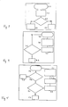
- FIG. 3 shows the flow diagram of a safety program according to the invention for the cyclical (self-) control of all sensor surfaces of the safety device.
- a control of the sensor surfaces takes place during a control run, e.g. by approaching a test specimen.
- the start of this inspection run takes place at regular intervals, e.g. every 24 hours 3.1.
- the device 2.1 intentionally triggers the safety function 3.2. This is followed by a check 3.3, whether the safety devices respond correctly. If this is the case, the device 2.1 is ready for an automatic operation 3.4. In the case of incorrectly responding safety devices, an error message appears 3.5.
- FIG. 4 shows the flow chart of the monitoring of a movement state of the device 2.1 by the motor current monitoring system according to the invention.
- FIG. 5 shows the flow chart of a combined movement monitoring of the device 2.1 by means of the motor current monitoring system illustrated in FIG. 4 and an additionally present force / torque sensor system.
- the combined motion monitoring comprises a measurement of the actually occurring motor currents 5.7 and a measurement of the forces and moments on an end effector (force / torque sensor) 5.8, based on which a comparison of the theoretically expected with the measured motor currents is carried out 5.1. If the deviation is within a tolerance range, the forces and moments are subsequently checked at the end effector 5.2. In the case of excessive deviation of the measured from the theoretical motor currents, an error message 5.3. A corresponding error message 5.5 takes place at excessive forces or moments at the end effector 5.2. In contrast, the movement of the device is continued 5.4, if both the measured motor currents and the measured forces and moments are in the respective tolerance range. The continuation of the movement is associated with a calculation of the motor currents to be expected in the motors of the device 2.1 on the basis of a mathematical model 5.6.
Landscapes
- Engineering & Computer Science (AREA)
- Mechanical Engineering (AREA)
- General Engineering & Computer Science (AREA)
- Robotics (AREA)
- Human Computer Interaction (AREA)
- Physics & Mathematics (AREA)
- Electromagnetism (AREA)
- Manipulator (AREA)
Applications Claiming Priority (2)
| Application Number | Priority Date | Filing Date | Title |
|---|---|---|---|
| DE10162412A DE10162412A1 (de) | 2001-12-19 | 2001-12-19 | Einrichtung und Verfahren zum Sichern von Vorrichtungen mit frei im Raum beweglichen Teilen |
| EP02027884A EP1323503B1 (fr) | 2001-12-19 | 2002-12-13 | Dispositif et méthode pour sécuriser un appareil possédant des parties mobiles libres |
Related Parent Applications (1)
| Application Number | Title | Priority Date | Filing Date |
|---|---|---|---|
| EP02027884A Division EP1323503B1 (fr) | 2001-12-19 | 2002-12-13 | Dispositif et méthode pour sécuriser un appareil possédant des parties mobiles libres |
Publications (1)
| Publication Number | Publication Date |
|---|---|
| EP1738882A2 true EP1738882A2 (fr) | 2007-01-03 |
Family
ID=7709819
Family Applications (3)
| Application Number | Title | Priority Date | Filing Date |
|---|---|---|---|
| EP06015847A Withdrawn EP1738882A2 (fr) | 2001-12-19 | 2002-12-13 | Dispositif et méthode pour sécuriser un appareil ayant des parties se déplaçant dans l'espace |
| EP02027884A Expired - Lifetime EP1323503B1 (fr) | 2001-12-19 | 2002-12-13 | Dispositif et méthode pour sécuriser un appareil possédant des parties mobiles libres |
| EP10012896A Withdrawn EP2338651A1 (fr) | 2001-12-19 | 2002-12-13 | Dispositif et procédé de sécurisation de dispositifs doté d'éléments se déplaçant librement dans l'espace |
Family Applications After (2)
| Application Number | Title | Priority Date | Filing Date |
|---|---|---|---|
| EP02027884A Expired - Lifetime EP1323503B1 (fr) | 2001-12-19 | 2002-12-13 | Dispositif et méthode pour sécuriser un appareil possédant des parties mobiles libres |
| EP10012896A Withdrawn EP2338651A1 (fr) | 2001-12-19 | 2002-12-13 | Dispositif et procédé de sécurisation de dispositifs doté d'éléments se déplaçant librement dans l'espace |
Country Status (3)
| Country | Link |
|---|---|
| US (1) | US7031807B2 (fr) |
| EP (3) | EP1738882A2 (fr) |
| DE (2) | DE10162412A1 (fr) |
Cited By (1)
| Publication number | Priority date | Publication date | Assignee | Title |
|---|---|---|---|---|
| DE102010063214A1 (de) | 2010-12-16 | 2012-06-21 | Robert Bosch Gmbh | Sicherungseinrichtung für eine Handhabungsvorrichtung, insbesondere einen Industrieroboter, sowie Verfahren zum Betreiben der Sicherungseinrichtung |
Families Citing this family (53)
| Publication number | Priority date | Publication date | Assignee | Title |
|---|---|---|---|---|
| DE102004013919A1 (de) * | 2004-03-22 | 2005-10-20 | Siemens Ag | Elektromotor |
| DE102004030144B4 (de) * | 2004-06-22 | 2007-09-06 | Fraunhofer-Gesellschaft zur Förderung der angewandten Forschung e.V. | Vorrichtung und Verfahren zur Nahbereichsdetektion um eine Robotereinheit |
| DE102004041821A1 (de) | 2004-08-27 | 2006-03-16 | Abb Research Ltd. | Vorrichtung und Verfahren zur Sicherung eines maschinell gesteuerten Handhabungsgerätes |
| DE202005002475U1 (de) * | 2005-02-15 | 2006-06-22 | Heiligensetzer, Peter, Dr.-Ing. | Kollisionskraftmindernde Schaumstoffabdeckung für Industrieroboter |
| DE102005027522B4 (de) * | 2005-06-15 | 2013-01-17 | Peter Heiligensetzer | Auswertverfahren |
| DE102005041606B4 (de) | 2005-09-01 | 2007-09-27 | Siemens Ag | Patientenpositioniervorrichtung für die Strahlentherapie |
| EP1810795A1 (fr) | 2006-01-19 | 2007-07-25 | Abb Ab | Dispositif de sécurité pour un robot industriel avec sac élastique étanche comprenant un fluide ou gaz |
| DE102006058785B4 (de) * | 2006-10-13 | 2019-03-21 | Fraba B.V. | Sensor zur berührungslosen und taktilen Hinderniserkennung |
| TWI322355B (en) * | 2006-10-17 | 2010-03-21 | Egis Technology Inc | Driverless signal generating apparatus and control method thereof |
| DE102006052017B4 (de) * | 2006-11-03 | 2009-03-05 | Homag Holzbearbeitungssysteme Ag | Bearbeitungsmaschine |
| DE102007006708A1 (de) | 2007-02-10 | 2008-08-14 | Abb Research Ltd. | Verfahren zur Sicherung eines Handhabungsgeräts |
| DE102007050232B4 (de) * | 2007-10-20 | 2024-05-02 | Deutsches Zentrum für Luft- und Raumfahrt e.V. | Handhabungsroboter und Verfahren zur Steuerung eines Handhabungsroboters |
| DE102007062245A1 (de) * | 2007-12-21 | 2009-06-25 | Robert Bosch Gmbh | Kollisionsdetektionsvorrichtung sowie Handhabungsgerät |
| DE102008041602B4 (de) * | 2008-08-27 | 2015-07-30 | Deutsches Zentrum für Luft- und Raumfahrt e.V. | Roboter und Verfahren zum Steuern eines Roboters |
| DE102008063081B4 (de) * | 2008-12-24 | 2014-10-23 | Gottfried Wilhelm Leibniz Universität Hannover | Sicherungsvorrichtung und Verfahren zum Betreiben einer mehrgliedrigen Maschine |
| JP4648486B2 (ja) * | 2009-01-26 | 2011-03-09 | ファナック株式会社 | 人間とロボットとの協調動作領域を有する生産システム |
| EP2411189B1 (fr) | 2009-03-27 | 2020-08-05 | Abb Ag | Petit robot à sécurité intrinsèque et procédé de commande de ce robot |
| DE102009029021B4 (de) | 2009-08-31 | 2022-09-22 | Robert Bosch Gmbh | Sensorsystem zur Umfeldüberwachung an einem mechanischen Bauteil und ein Verfahren zur Ansteuerung und Auswertung des Sensorsystems |
| DE102010063223A1 (de) * | 2010-12-16 | 2012-06-21 | Robert Bosch Gmbh | Einrichtung zum Abführen von Wärme aus einer automatisierten Handhabungseinrichtung, insbesondere einem Handhabungsroboter, und Verwendung der Einrichtung |
| DE102010063208A1 (de) * | 2010-12-16 | 2012-06-21 | Robert Bosch Gmbh | Verfahren zum Betreiben einer Sicherungseinrichtung für eine Handhabungsvorrichtung, Sicherungseinrichtung für eine Handhabungsvorrichtung und Handhabungsvorrichtung |
| DE202011052253U1 (de) * | 2011-12-09 | 2012-01-31 | Mayser Gmbh & Co. Kg | Kollisionsschutz |
| US20130245823A1 (en) * | 2012-03-19 | 2013-09-19 | Kabushiki Kaisha Yaskawa Denki | Robot system, robot hand, and robot system operating method |
| DE102012217762B4 (de) * | 2012-09-28 | 2023-05-17 | Homag Holzbearbeitungssysteme Gmbh | Bumper mit integriertem Sensor |
| DE102013106704A1 (de) * | 2013-06-26 | 2014-12-31 | Hartmut Fuchs | Vorrichtung zur berührungslosen Detektion und/oder Abstandsermittlung mindestens eines Objektes relativ zu einem Messkörper sowie Verfahren dazu |
| CN103386684B (zh) * | 2013-08-21 | 2016-02-24 | 福州大学 | 一种防止机器人产生意外碰撞的装置及设计方法 |
| DE202013104860U1 (de) * | 2013-10-30 | 2015-02-02 | Daimler Ag | Arbeitsvorrichtung |
| DE202013105036U1 (de) | 2013-11-08 | 2015-02-10 | Daimler Ag | Erfassungseinrichtung |
| DE102013021387B4 (de) | 2013-12-13 | 2019-09-12 | Daimler Ag | Roboter sowie Verfahren zum Betreiben eines solchen Roboters |
| JP5902664B2 (ja) | 2013-12-25 | 2016-04-13 | ファナック株式会社 | 保護部材を有する人協調型産業用ロボット |
| DE102014207275A1 (de) | 2014-04-15 | 2015-10-15 | Kuka Systems Gmbh | Robotervorrichtung mit einer Linearachse |
| JP6140114B2 (ja) * | 2014-07-31 | 2017-05-31 | ファナック株式会社 | 移動式人協調型ロボット |
| DE102014014835A1 (de) * | 2014-10-07 | 2016-04-07 | Audi Ag | Anordnung zum Erkennen einer unfallbedingten Beschädigung eines Bauteils |
| JP6677441B2 (ja) * | 2014-10-20 | 2020-04-08 | 株式会社デンソーウェーブ | ロボット、ロボットの形状設計方法 |
| CN104444351B (zh) * | 2014-11-07 | 2016-11-02 | 京东方科技集团股份有限公司 | 机械手臂及基板拾取装置 |
| DE102014225252A1 (de) * | 2014-12-09 | 2016-06-09 | Kuka Systems Gmbh | Verfahren zum Überwachen wenigstens eines Industrieroboters, Industrieroboter und System mit mehreren Industrierobotern |
| JP5937706B1 (ja) * | 2015-01-21 | 2016-06-22 | ファナック株式会社 | ロボットに加わる外力に基づいてロボットを制御するロボット制御装置、およびロボットシステム |
| DE102015017282B3 (de) | 2015-10-08 | 2021-09-16 | Franka Emika Gmbh | Robotersystem und Verfahren zur Steuerung eines Robotersystems |
| US10994426B2 (en) * | 2016-04-11 | 2021-05-04 | Persimmon Technologies Corporation | Robotic manipulator with supplementary damping |
| DE102016206866A1 (de) * | 2016-04-22 | 2017-10-26 | Robert Bosch Gmbh | Handarbeitsplatz und Steuereinheit zur Ablaufsteuerung eines Handarbeitsplatzes |
| FR3050393B1 (fr) * | 2016-04-22 | 2021-03-19 | Bosch Gmbh Robert | Poste de travail et unite de commande de son fonctionnement |
| ITUA20163522A1 (it) * | 2016-05-17 | 2017-11-17 | Comau Spa | "Copertura sensorizzata per un dispositivo industriale" |
| ITUA20163520A1 (it) * | 2016-05-17 | 2017-11-17 | Comau Spa | "Dispositivo automatizzato con una struttura mobile, particolarmente un robot" |
| CN107717982B (zh) * | 2016-08-12 | 2020-09-25 | 财团法人工业技术研究院 | 机械手臂的控制装置及操作方法 |
| ES2760947T3 (es) | 2017-06-23 | 2020-05-18 | Comau Spa | Conjunto funcional para una máquina industrial, en concreto para un robot, que incluye una unidad funcional equipada con una cubierta de seguridad |
| EP3427904B1 (fr) * | 2017-07-13 | 2020-06-10 | Siemens Aktiengesellschaft | Système comprenant un manipulateur et un dispositif de limitation d'un espace de travail |
| IT201700121883A1 (it) | 2017-10-26 | 2019-04-26 | Comau Spa | "Dispositivo automatizzato con una struttura mobile, in particolare un robot" |
| DE102018206019B4 (de) * | 2018-04-19 | 2021-01-21 | Kuka Deutschland Gmbh | Robotersystem und Verfahren zum Betreiben des Robotersystems |
| JP7014114B2 (ja) * | 2018-09-25 | 2022-02-01 | オムロン株式会社 | エンドエフェクタおよびエンドエフェクタ装置 |
| JP2021020286A (ja) * | 2019-07-30 | 2021-02-18 | セイコーエプソン株式会社 | 検出方法およびロボット |
| DE102020116021A1 (de) | 2020-06-17 | 2021-12-23 | Pilz Gmbh & Co. Kg | Sicherheitseinrichtung und Verfahren zur Absicherung einer Maschine |
| CA3208465A1 (fr) | 2021-03-03 | 2022-09-09 | Guardian Glass, LLC | Systemes et/ou procedes de creation et de detection de changements dans des champs electriques |
| CN113188591B (zh) * | 2021-04-09 | 2023-08-11 | 苏州大学 | 面向空间在轨装配机器人的自供电多模态感知装置及方法 |
| CN114734452B (zh) * | 2022-05-17 | 2024-02-23 | 浙江理工大学 | 一种基于压阻信号的机械臂碰撞监测方法 |
Family Cites Families (28)
| Publication number | Priority date | Publication date | Assignee | Title |
|---|---|---|---|---|
| US3725918A (en) * | 1970-11-18 | 1973-04-03 | Sperry Rand Corp | Collision avoidance display apparatus for maneuverable craft |
| DE2854459A1 (de) | 1978-12-16 | 1980-08-28 | Fraunhofer Ges Forschung | Sicherheitseinrichtung fuer anlagen mit in den raum bewegten teilen |
| DE3570385D1 (en) * | 1984-04-09 | 1989-06-29 | Elektroniktechnologie Get | Electronic surveillance and warning device for a manipulator |
| GB8426010D0 (en) | 1984-10-15 | 1984-11-21 | Memco Med Ltd | Automatic control |
| FR2595441B1 (fr) * | 1986-03-05 | 1988-08-05 | Univ Metz | Dispositif de securite a detecteur de contact |
| US4733068A (en) * | 1986-04-07 | 1988-03-22 | Rockwell International Corporation | Crossed fiber optic tactile sensor |
| US4751658A (en) * | 1986-05-16 | 1988-06-14 | Denning Mobile Robotics, Inc. | Obstacle avoidance system |
| CH682351A5 (fr) | 1986-10-16 | 1993-08-31 | Sohard Ag | |
| JPS63238502A (ja) * | 1987-03-27 | 1988-10-04 | Yokohama Rubber Co Ltd:The | 近接覚・触覚センサ |
| DE3715693C1 (de) * | 1987-05-12 | 1988-09-01 | Deutsche Forsch Luft Raumfahrt | Flaechiger,taktiler Sensor |
| US4968878A (en) * | 1989-02-07 | 1990-11-06 | Transitions Research Corporation | Dual bumper-light curtain obstacle detection sensor |
| DE4006119A1 (de) | 1990-02-27 | 1991-08-29 | Ines Gmbh | Kapazitives wegaufnehmersystem |
| USRE36772E (en) * | 1991-06-06 | 2000-07-11 | The United States Of America As Represented By The Administrator Of The National Aeronautics And Space Administration | Driven shielding capacitive proximity sensor |
| US5166679A (en) | 1991-06-06 | 1992-11-24 | The United States Of America As Represented By The Administrator Of The National Aeronautics & Space Administration | Driven shielding capacitive proximity sensor |
| US5400244A (en) * | 1991-06-25 | 1995-03-21 | Kabushiki Kaisha Toshiba | Running control system for mobile robot provided with multiple sensor information integration system |
| NL9200286A (nl) * | 1992-02-17 | 1993-09-16 | Sven Ploem | Botsvrij besturingssysteem voor een meerassig bestuurbare manipulator. |
| US5280622A (en) * | 1992-07-17 | 1994-01-18 | Mitsubishi Semiconductor America, Inc. | Combined light beam and ultrasonic transducer safety sensing system |
| JPH08393B2 (ja) * | 1993-03-26 | 1996-01-10 | 日本電気株式会社 | 衝突防止機能付ロボットアーム |
| US5373245A (en) * | 1993-07-12 | 1994-12-13 | The United States Of America As Represented By The Administrator Of The National Aeronautics And Space Administration | Capaciflector camera |
| SE502834C2 (sv) * | 1994-03-29 | 1996-01-29 | Electrolux Ab | Förfarande och anordning för avkänning av hinder vid självgående anordning |
| JP3077514B2 (ja) | 1994-06-28 | 2000-08-14 | トヨタ自動車株式会社 | ロボット |
| DE4428650A1 (de) | 1994-08-12 | 1996-02-15 | Marinitsch Waldemar | Optische Druckkrafterfassungsvorrichtung |
| JP3249424B2 (ja) * | 1997-03-13 | 2002-01-21 | 川崎重工業株式会社 | 光学式ロボット用接触センサ |
| US6481515B1 (en) * | 2000-05-30 | 2002-11-19 | The Procter & Gamble Company | Autonomous mobile surface treating apparatus |
| US6539284B2 (en) * | 2000-07-25 | 2003-03-25 | Axonn Robotics, Llc | Socially interactive autonomous robot |
| KR100523367B1 (ko) * | 2000-10-26 | 2005-10-20 | 마츠시다 덴코 가부시키가이샤 | 장해물 회피기능을 가지는 자율이동장치 |
| US6676460B1 (en) * | 2001-07-05 | 2004-01-13 | Maruta Electric Boatworks Llc | Electronic propeller guard |
| DE10226853B3 (de) * | 2002-06-15 | 2004-02-19 | Kuka Roboter Gmbh | Verfahren zum Begrenzen der Krafteinwirkung eines Roboterteils |
-
2001
- 2001-12-19 DE DE10162412A patent/DE10162412A1/de not_active Ceased
-
2002
- 2002-12-13 DE DE50214879T patent/DE50214879D1/de not_active Expired - Lifetime
- 2002-12-13 EP EP06015847A patent/EP1738882A2/fr not_active Withdrawn
- 2002-12-13 EP EP02027884A patent/EP1323503B1/fr not_active Expired - Lifetime
- 2002-12-13 EP EP10012896A patent/EP2338651A1/fr not_active Withdrawn
- 2002-12-17 US US10/321,007 patent/US7031807B2/en not_active Expired - Lifetime
Cited By (3)
| Publication number | Priority date | Publication date | Assignee | Title |
|---|---|---|---|---|
| DE102010063214A1 (de) | 2010-12-16 | 2012-06-21 | Robert Bosch Gmbh | Sicherungseinrichtung für eine Handhabungsvorrichtung, insbesondere einen Industrieroboter, sowie Verfahren zum Betreiben der Sicherungseinrichtung |
| WO2012080130A1 (fr) | 2010-12-16 | 2012-06-21 | Robert Bosch Gmbh | Dispositif de sécurité pour un manipulateur, en particulier un robot industriel, et procédé pour faire fonctionner le dispositif de sécurité |
| US9475200B2 (en) | 2010-12-16 | 2016-10-25 | Robert Bosch Gmbh | Safety device for a handling apparatus, in particular an industrial robot, and method for operating the safety device |
Also Published As
| Publication number | Publication date |
|---|---|
| DE10162412A1 (de) | 2003-07-10 |
| EP1323503B1 (fr) | 2011-01-26 |
| EP1323503A2 (fr) | 2003-07-02 |
| DE50214879D1 (de) | 2011-03-10 |
| EP1323503A3 (fr) | 2003-08-06 |
| US7031807B2 (en) | 2006-04-18 |
| US20030137219A1 (en) | 2003-07-24 |
| EP2338651A1 (fr) | 2011-06-29 |
Similar Documents
| Publication | Publication Date | Title |
|---|---|---|
| EP1323503B1 (fr) | Dispositif et méthode pour sécuriser un appareil possédant des parties mobiles libres | |
| EP2989369B1 (fr) | Dispositif et procédé de sécurisation d'une machine travaillant de manière automatisée | |
| EP1306603B2 (fr) | Procédé et dispositif de commande d'une fonction relative à la sécurité d'une machine | |
| EP3393709B1 (fr) | Dispositif d'usinage | |
| EP1367314B1 (fr) | Dispositif de surveillance du champ d'action d'un organe de travail | |
| EP2659233B1 (fr) | Système de détection destiné à surveiller l'environnement d'une pièce mécanique et procédé de commande et d'évaluation dudit système de détection | |
| EP1353196B1 (fr) | Détection d'un objet et barrière optique | |
| DE102010063214A1 (de) | Sicherungseinrichtung für eine Handhabungsvorrichtung, insbesondere einen Industrieroboter, sowie Verfahren zum Betreiben der Sicherungseinrichtung | |
| EP1918629B1 (fr) | Machine de traitement | |
| DE102018104082B4 (de) | Robotersystem | |
| AT412071B (de) | Fertigungseinrichtung, insbesondere abkantpresse, und verfahren zum betrieb einer fertigungseinrichtung | |
| EP2825812A1 (fr) | Procédé et dispositif destinés sécuriser une zone de travail dangereuse d'une machine à fonctionnement automatique. | |
| EP2306063B1 (fr) | Capteur de sécurité | |
| WO2018145990A1 (fr) | Dispositif pour sécuriser un manipulateur à commande mécanique et procédé | |
| EP3575666B1 (fr) | Dispositif de sécurisation d'une zone à risque d'une installation | |
| EP2114629B1 (fr) | Procédé de sécurisation d'un appareil de manipulation | |
| EP3600794A1 (fr) | Procédé de surveillance et système de surveillance | |
| EP3753689B1 (fr) | Dispositif de détection d'une collision pour systèmes de préhension et procédé de détection d'une collision | |
| EP2625008B1 (fr) | Commande de robot | |
| DE102005027522B4 (de) | Auswertverfahren | |
| DE102007036677A1 (de) | Sicherheitssensor | |
| EP3394983B1 (fr) | Procédé de fonctionnement d'un système de détection, élément de détection et système de détection | |
| EP3427904B1 (fr) | Système comprenant un manipulateur et un dispositif de limitation d'un espace de travail | |
| EP4290117A1 (fr) | Dispositif de surveillance | |
| DE202007019467U1 (de) | Sicherheitssensor |
Legal Events
| Date | Code | Title | Description |
|---|---|---|---|
| PUAI | Public reference made under article 153(3) epc to a published international application that has entered the european phase |
Free format text: ORIGINAL CODE: 0009012 |
|
| 17P | Request for examination filed |
Effective date: 20060729 |
|
| AC | Divisional application: reference to earlier application |
Ref document number: 1323503 Country of ref document: EP Kind code of ref document: P |
|
| AK | Designated contracting states |
Kind code of ref document: A2 Designated state(s): DE FR GB IT SE |
|
| RIN1 | Information on inventor provided before grant (corrected) |
Inventor name: HEILIGENSETZER, PETER Inventor name: STEININGER, FRITZ |
|
| STAA | Information on the status of an ep patent application or granted ep patent |
Free format text: STATUS: THE APPLICATION HAS BEEN WITHDRAWN |
|
| 18W | Application withdrawn |
Effective date: 20101007 |