EP1738930A2 - Fahrzeugluftreifen - Google Patents
Fahrzeugluftreifen Download PDFInfo
- Publication number
- EP1738930A2 EP1738930A2 EP06007750A EP06007750A EP1738930A2 EP 1738930 A2 EP1738930 A2 EP 1738930A2 EP 06007750 A EP06007750 A EP 06007750A EP 06007750 A EP06007750 A EP 06007750A EP 1738930 A2 EP1738930 A2 EP 1738930A2
- Authority
- EP
- European Patent Office
- Prior art keywords
- bead
- rim
- heel
- side point
- width
- Prior art date
- Legal status (The legal status is an assumption and is not a legal conclusion. Google has not performed a legal analysis and makes no representation as to the accuracy of the status listed.)
- Withdrawn
Links
- 239000011324 bead Substances 0.000 claims abstract description 89
- 229910000831 Steel Inorganic materials 0.000 description 3
- 239000004760 aramid Substances 0.000 description 3
- 229920003235 aromatic polyamide Polymers 0.000 description 3
- 238000006073 displacement reaction Methods 0.000 description 3
- 239000000835 fiber Substances 0.000 description 3
- 239000010959 steel Substances 0.000 description 3
- 229920000297 Rayon Polymers 0.000 description 2
- 230000002542 deteriorative effect Effects 0.000 description 2
- 239000002964 rayon Substances 0.000 description 2
- 239000004677 Nylon Substances 0.000 description 1
- 230000001133 acceleration Effects 0.000 description 1
- 229920001778 nylon Polymers 0.000 description 1
- 229920000728 polyester Polymers 0.000 description 1
- 238000004804 winding Methods 0.000 description 1
Images



Classifications
-
- B—PERFORMING OPERATIONS; TRANSPORTING
- B60—VEHICLES IN GENERAL
- B60C—VEHICLE TYRES; TYRE INFLATION; TYRE CHANGING; CONNECTING VALVES TO INFLATABLE ELASTIC BODIES IN GENERAL; DEVICES OR ARRANGEMENTS RELATED TO TYRES
- B60C15/00—Tyre beads, e.g. ply turn-up or overlap
- B60C15/02—Seating or securing beads on rims
- B60C15/024—Bead contour, e.g. lips, grooves, or ribs
-
- Y—GENERAL TAGGING OF NEW TECHNOLOGICAL DEVELOPMENTS; GENERAL TAGGING OF CROSS-SECTIONAL TECHNOLOGIES SPANNING OVER SEVERAL SECTIONS OF THE IPC; TECHNICAL SUBJECTS COVERED BY FORMER USPC CROSS-REFERENCE ART COLLECTIONS [XRACs] AND DIGESTS
- Y10—TECHNICAL SUBJECTS COVERED BY FORMER USPC
- Y10T—TECHNICAL SUBJECTS COVERED BY FORMER US CLASSIFICATION
- Y10T152/00—Resilient tires and wheels
- Y10T152/10—Tires, resilient
- Y10T152/10495—Pneumatic tire or inner tube
- Y10T152/10819—Characterized by the structure of the bead portion of the tire
Definitions
- the present invention relates to a pneumatic tire, more particularly to an improved bead profile which can improve resistance to displacement on a rim without deteriorating rim-mounting performance.
- a bead portion (a) of a pneumatic tire comprises: a bead base (a1) with a heel diameter of Dp at the axially outer end thereof; and a bead core (c).
- the heel diameter Db for example, has a smaller 0.7% than a rim-diameter (Dr) of a standard rim R so that the bead base (a1) is fastened onto a rim base Rb of the rim R tightly.
- Dr rim-diameter
- air filled up in the pneumatic tire forces the bead portion (a) to contact a rim flange Rf of the rim R.
- the tire is mounted on the rim tightly.
- the bead portion (a) tends to be displaced to the inside of the tire axial direction according to a decrease of the air. Further, if a side force is applied into the tire with such a condition, the bead portion (a) may be slipped on the rim base Rb, and then drop into rim well (not shown) of the rim R with getting over a hump Rb1.
- an object of the present invention to provide a pneumatic tire with an improved bead profile which can improve resistance to displacement on a rim without deteriorating rim-mounting performance.
- a pneumatic tire to be mounted on a rim comprises
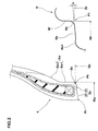
- a pneumatic tire 1 is a tubeless type for passenger car.
- the pneumatic tire 1 comprises: a tread portion 2; a pair of sidewall portions 3; a pair of bead portions 4 each with a bead core 5 therein; a carcass 6 comprising at least one ply 6A of cords; and a belt 7 disposed radially outside the carcass in the tread portion 2.
- the carcass 6 comprises at least one ply 6A of cords inclined at angle of from 70 to 90 degrees with respect to the tire equator C.
- the carcass 6 comprises one carcass ply 6A.
- organic fiber cords e.g. aromatic polyamide, polyester, rayon, nylon and the like can be suitably used.
- steel cords also may be used.
- the carcass ply 6A extends between the bead portions 4 and turned up around the bead core 5 in each bead portion 4 from the axially inside to outside of the tire so as to form a pair of turnup portions 6b and a main portion 6a therebetween.
- a rubber bead apex 8 between the main portion 6a and the turnup portion 6b is disposed in each bead portion 4.
- the bead apex 8 extends and tapers from an radially outer surface of the bead core 5.
- the belt 7 comprises two cross belt plies 7 A and 7 B of parallel cords laid at an angle of from 10 to 35 degrees with respect to the tire equator c.
- steel cords, and high modulus organic fiber cords such as aramid, rayon and like can be used.
- a band 9 which covers with both shoulder regions of the belt 7 at least and has cords with an angle of not more than 5 degrees with respect to the tire equator C is disposed radially outside the belt 7 in the tread portion 2.
- the bead core 5 is a ring formed by winding a wire predetermined times into a rectangular cross sectional shape in this example.
- a steel wire is preferable, but high modulus organic fiber cords, e.g. aromatic polyamide and the like can be used.
- a rim R for mounting the tire 1, as shown in Fig.2, has a profile for contacting with tire which comprises a rim base surface Rb extending substantially straight with an inclination angle alpha with respect to the tire axial direction, an inner surface Rf of a rim flange extending substantially vertically, a heel surface Rh connecting between the rim base surface Rb and the inner surface Rf of the rim flange and curved into a circular arc, and a hump Rb1 provided with axially inside of the rim base surface Rb and protruding outside in the tire radial direction.
- the rim R according to the present embodiment is a five-degree taper rim which has a taper angle alpha of the rim base surface Rb is about 5 degrees with respect to the tire axial direction. Further, the rim R has a rim-diameter Dr that is a diameter of an intersecting point P1 of an expanded lines of the rim base surface Rb with an expanded line of the inner surface Rf of the rim flange.
- rim R a standard rim is used.
- the standard rim is the "standard rim” specified in JATMA, the "Measuring Rim” in ETRTO, the “Design Rim” in TRA or the like.
- the bead portion 4 has a profile comprising: a bead toe Pt; a heel side point Ph which is a point on the bead surface near the heel and has a diameter DP in a range of from 99.1 to 99.3 % of the rim-diameter Dr of the rim R; a bead base sb which extends from the bead toe Pt to the heel-side point Ph and to be mounted on the rim base surface Rb; an axially outer surface sw to be supported by the inner surface Rf of the rim flange; and a heel surface sh connecting between the bead surface sb and the outer surface Sw and curved into a circular arc.
- the outer surface Sw comprises an inside part sw1 which extends straight from the heel surface sh to the radially outside and is supported by the inner surface Rf of the rim flange Rf and an outside part Sw2 which is provided radially outside the inside part Sw2.
- the bead base sb comprises a straight part 20 and a convex part 21 as shown in Figs. 2 and 3.
- the straight part 20 extends from the bead toe Pt toward the heel-side point Ph with an inclination theta so that an extended line N of the straight part 20 passes through the heel-side point Pt.
- the angle theta of the inclination of the straight part 20 is preferably more than 0 degree but not more than 15 degrees with respect to the tire axial direction.
- the convex part 21 is provided between the axially outer end 20e of the straight part 20 and the heel-side point Ph, and protrudes toward inside from the extended line N.
- the convex part 21 is formed into a circular arc with a radius of curvature r of from 0.20 to 0.33 times a base width w1 of the bead base Sb.
- the bead base width w1 is a width between the bead toe Pt and the heel-side point Ph in the tire axial direction.
- the convex part 21 has a protruding height Hd perpendicular from the extended line N of from 0.067 to 0.13 times the bead base width W1.
- the convex part 21 can work as a friction brake which prevents a slip of the bead base sb with the rim base surface Rb.
- the tire 1 in accordance with the present invention can improve resistance to displacement of the bead portion 4.
- the convex part 21 cannot work effectively to prevent such a slip with the rim base surface Rb.
- the convex part 21 has an axial width w2 of from 0.20 to 0.33 times the bead base width w1 of the bead base Sb.
- the convex part 21 and the heel part sh are drawn by a single circular arc having the radius of curvature r which extending from the axially outer end 20e of the straight part 20 to an end of the heel surface sh.
- these parts 21 and sb each may have its own circular arc with different radius of curvature each other.
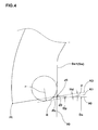
- Fig. 4 shows a profile of the bead portion 4 in accordance with the present invention for explaining one aspect of how to design thereof.
- a first inclined line K0 that has the angle theta with respect to the tire axial direction and passes through a point J0 which intersects an extended line Y0 of the inside part Sw1 with an axial line having a diameter Da is defined.
- the diameter Da is substantially equal to the diameter Db as shown in Fig.5.
- the diameter Da has a smaller 0.7% than the rim-diameter Dr.
- the second inclined line K1 that is parallel to the first inclined line K0 and separates from the line K0 with a distance Hd is defined.
- a circular arc R which has the radius of curvature r and comes into contact with both a surface of the inside part sw1 of the bead portion and the second inclined line K1 is defined so that the diameter Dp of the heel-side point Ph is 99.1 to 99.3 % of the rim-diameter Dr.
- Test tires of size 205/60R16 having the same structure shown in Figs. 2 and 3 except for the bead profile were made and tested for the resistance to bead unseating and the difficulty in mounting the tire on a standard rim as follows.
- the results are indicated in Table 1 by an index based on Ref.1 being 100, wherein the larger the index number, the better the resistance to bead unseating.
- the test tires were mounted on a standard rim, and the degree of difficulty was evaluated by a skilled person.
- the results are indicated in Table 1 by an index based on Ref.1 being 100, wherein the smaller the index number, the better the tire mounting test.
- the quality passed of the mounting test is indicated by the index number of 90 or more
Landscapes
- Engineering & Computer Science (AREA)
- Mechanical Engineering (AREA)
- Tires In General (AREA)
Applications Claiming Priority (1)
| Application Number | Priority Date | Filing Date | Title |
|---|---|---|---|
| JP2005188609 | 2005-06-28 |
Publications (2)
| Publication Number | Publication Date |
|---|---|
| EP1738930A2 true EP1738930A2 (de) | 2007-01-03 |
| EP1738930A3 EP1738930A3 (de) | 2012-03-28 |
Family
ID=37056811
Family Applications (1)
| Application Number | Title | Priority Date | Filing Date |
|---|---|---|---|
| EP06007750A Withdrawn EP1738930A3 (de) | 2005-06-28 | 2006-04-12 | Fahrzeugluftreifen |
Country Status (3)
| Country | Link |
|---|---|
| US (1) | US7493929B2 (de) |
| EP (1) | EP1738930A3 (de) |
| CN (1) | CN100556719C (de) |
Families Citing this family (6)
| Publication number | Priority date | Publication date | Assignee | Title |
|---|---|---|---|---|
| US8627866B2 (en) * | 2009-01-09 | 2014-01-14 | Bridgestone Americas Tire Operations, Llc | Tire and wheel rim assembly |
| US10160268B2 (en) * | 2013-07-26 | 2018-12-25 | Hendrickson Usa, L.L.C. | Central tire pressure monitoring system |
| JP6325909B2 (ja) * | 2014-06-13 | 2018-05-16 | 株式会社ブリヂストン | タイヤ |
| JP6927002B2 (ja) * | 2017-12-06 | 2021-08-25 | 住友ゴム工業株式会社 | 空気入りタイヤ |
| JP7067213B2 (ja) * | 2018-04-04 | 2022-05-16 | 横浜ゴム株式会社 | 空気入りタイヤ |
| JP7110897B2 (ja) * | 2018-10-11 | 2022-08-02 | 横浜ゴム株式会社 | 空気入りタイヤ |
Family Cites Families (8)
| Publication number | Priority date | Publication date | Assignee | Title |
|---|---|---|---|---|
| FR1157542A (fr) * | 1956-09-03 | 1958-05-30 | Dunlop Sa | Perfectionnement à l'étanchéité des enveloppes sans chambre |
| JPS53114102A (en) * | 1977-03-15 | 1978-10-05 | Toyo Tire & Rubber Co Ltd | Air sealing tire |
| DE7818339U1 (de) * | 1978-06-19 | 1979-11-29 | Uniroyal Gmbh, 5100 Aachen | Fahrzeug-radialluftreifen mit wulst- klemmdichtung |
| FR2548970B1 (fr) * | 1983-06-23 | 1985-10-18 | Michelin & Cie | Pneumatique a carcasse radiale, utilisable sans chambre a air independante et dote de bourrelets renforces par au moins une tringle, pouvant etre montes sur une jante a siege tronconique |
| JP3643191B2 (ja) * | 1995-11-29 | 2005-04-27 | 株式会社ブリヂストン | トラック及びバス用15°テーパラジアルタイヤ |
| JP2733730B2 (ja) | 1992-12-28 | 1998-03-30 | 住友ゴム工業株式会社 | 空気入りタイヤ |
| JP3485413B2 (ja) * | 1996-03-29 | 2004-01-13 | 住友ゴム工業株式会社 | 空気入りタイヤのビード部構造 |
| CN1386653A (zh) * | 2001-05-21 | 2002-12-25 | 住友橡胶工业株式会社 | 充气轮胎 |
-
2006
- 2006-04-10 US US11/400,307 patent/US7493929B2/en not_active Expired - Fee Related
- 2006-04-12 EP EP06007750A patent/EP1738930A3/de not_active Withdrawn
- 2006-04-24 CN CN200610075852.2A patent/CN100556719C/zh not_active Expired - Fee Related
Non-Patent Citations (1)
| Title |
|---|
| None |
Also Published As
| Publication number | Publication date |
|---|---|
| EP1738930A3 (de) | 2012-03-28 |
| US7493929B2 (en) | 2009-02-24 |
| CN1891504A (zh) | 2007-01-10 |
| US20060289103A1 (en) | 2006-12-28 |
| CN100556719C (zh) | 2009-11-04 |
Similar Documents
| Publication | Publication Date | Title |
|---|---|---|
| EP3127717B1 (de) | Luftreifen | |
| EP3482977B1 (de) | Schwerlastluftreifen | |
| US20110056607A1 (en) | Heavy duty pneumatic tire | |
| EP3482976B1 (de) | Schwerlastluftreifen | |
| US6321806B1 (en) | Pneumatic tire with rim flange holder | |
| EP3995322B1 (de) | Reifen und gürtelschicht | |
| EP1683654B1 (de) | Notlaufreifen | |
| EP3366495B1 (de) | Reifen für ein zweirädriges automobiles fahrzeug | |
| EP3235664B1 (de) | Luftreifen | |
| EP3202599B1 (de) | Luftreifen | |
| EP1612058B1 (de) | Motorradreifen | |
| EP1738930A2 (de) | Fahrzeugluftreifen | |
| EP2602125B1 (de) | Luftreifen | |
| EP3789216B1 (de) | Luftreifen | |
| EP3636454B1 (de) | Reifen | |
| US20220134809A1 (en) | Pneumatic tire | |
| EP3536522B1 (de) | Notlaufringreifen | |
| EP4606599A1 (de) | Luftreifen | |
| EP1782971B1 (de) | Motorradreifen | |
| EP3189988B1 (de) | Luftreifen | |
| EP4321351B1 (de) | Reifen | |
| US12552200B2 (en) | Tire with specified profile | |
| EP4512639B1 (de) | Luftreifen | |
| EP4613508A2 (de) | Luftreifen | |
| EP4410569A1 (de) | Luftreifen |
Legal Events
| Date | Code | Title | Description |
|---|---|---|---|
| PUAI | Public reference made under article 153(3) epc to a published international application that has entered the european phase |
Free format text: ORIGINAL CODE: 0009012 |
|
| AK | Designated contracting states |
Kind code of ref document: A2 Designated state(s): AT BE BG CH CY CZ DE DK EE ES FI FR GB GR HU IE IS IT LI LT LU LV MC NL PL PT RO SE SI SK TR |
|
| AX | Request for extension of the european patent |
Extension state: AL BA HR MK YU |
|
| PUAL | Search report despatched |
Free format text: ORIGINAL CODE: 0009013 |
|
| AK | Designated contracting states |
Kind code of ref document: A3 Designated state(s): AT BE BG CH CY CZ DE DK EE ES FI FR GB GR HU IE IS IT LI LT LU LV MC NL PL PT RO SE SI SK TR |
|
| AX | Request for extension of the european patent |
Extension state: AL BA HR MK YU |
|
| RIC1 | Information provided on ipc code assigned before grant |
Ipc: B60C 15/024 20060101AFI20120221BHEP |
|
| 17P | Request for examination filed |
Effective date: 20120702 |
|
| GRAP | Despatch of communication of intention to grant a patent |
Free format text: ORIGINAL CODE: EPIDOSNIGR1 |
|
| RAP1 | Party data changed (applicant data changed or rights of an application transferred) |
Owner name: SUMITOMO RUBBER INDUSTRIES, LTD. |
|
| RIN1 | Information on inventor provided before grant (corrected) |
Inventor name: SUZUKI, KAZUYA C/O SUMITOMO RUBBER INDUSTRIES, LTD |
|
| AKX | Designation fees paid |
Designated state(s): DE FR GB |
|
| STAA | Information on the status of an ep patent application or granted ep patent |
Free format text: STATUS: THE APPLICATION IS DEEMED TO BE WITHDRAWN |
|
| 18D | Application deemed to be withdrawn |
Effective date: 20130209 |