EP1738990B1 - Circuit élévateur de tension et direction assistée électrique - Google Patents
Circuit élévateur de tension et direction assistée électrique Download PDFInfo
- Publication number
- EP1738990B1 EP1738990B1 EP06004665A EP06004665A EP1738990B1 EP 1738990 B1 EP1738990 B1 EP 1738990B1 EP 06004665 A EP06004665 A EP 06004665A EP 06004665 A EP06004665 A EP 06004665A EP 1738990 B1 EP1738990 B1 EP 1738990B1
- Authority
- EP
- European Patent Office
- Prior art keywords
- steering
- switching device
- circuit
- voltage
- motor
- Prior art date
- Legal status (The legal status is an assumption and is not a legal conclusion. Google has not performed a legal analysis and makes no representation as to the accuracy of the status listed.)
- Expired - Lifetime
Links
Images



Classifications
-
- B—PERFORMING OPERATIONS; TRANSPORTING
- B62—LAND VEHICLES FOR TRAVELLING OTHERWISE THAN ON RAILS
- B62D—MOTOR VEHICLES; TRAILERS
- B62D5/00—Power-assisted or power-driven steering
- B62D5/04—Power-assisted or power-driven steering electrical, e.g. using an electric servo-motor connected to, or forming part of, the steering gear
- B62D5/0457—Power-assisted or power-driven steering electrical, e.g. using an electric servo-motor connected to, or forming part of, the steering gear characterised by control features of the drive means as such
- B62D5/0481—Power-assisted or power-driven steering electrical, e.g. using an electric servo-motor connected to, or forming part of, the steering gear characterised by control features of the drive means as such monitoring the steering system, e.g. failures
- B62D5/0484—Power-assisted or power-driven steering electrical, e.g. using an electric servo-motor connected to, or forming part of, the steering gear characterised by control features of the drive means as such monitoring the steering system, e.g. failures for reaction to failures, e.g. limp home
-
- B—PERFORMING OPERATIONS; TRANSPORTING
- B60—VEHICLES IN GENERAL
- B60W—CONJOINT CONTROL OF VEHICLE SUB-UNITS OF DIFFERENT TYPE OR DIFFERENT FUNCTION; CONTROL SYSTEMS SPECIALLY ADAPTED FOR HYBRID VEHICLES; ROAD VEHICLE DRIVE CONTROL SYSTEMS FOR PURPOSES NOT RELATED TO THE CONTROL OF A PARTICULAR SUB-UNIT
- B60W10/00—Conjoint control of vehicle sub-units of different type or different function
- B60W10/20—Conjoint control of vehicle sub-units of different type or different function including control of steering systems
-
- B—PERFORMING OPERATIONS; TRANSPORTING
- B62—LAND VEHICLES FOR TRAVELLING OTHERWISE THAN ON RAILS
- B62D—MOTOR VEHICLES; TRAILERS
- B62D5/00—Power-assisted or power-driven steering
- B62D5/04—Power-assisted or power-driven steering electrical, e.g. using an electric servo-motor connected to, or forming part of, the steering gear
- B62D5/0457—Power-assisted or power-driven steering electrical, e.g. using an electric servo-motor connected to, or forming part of, the steering gear characterised by control features of the drive means as such
- B62D5/046—Controlling the motor
-
- B—PERFORMING OPERATIONS; TRANSPORTING
- B62—LAND VEHICLES FOR TRAVELLING OTHERWISE THAN ON RAILS
- B62D—MOTOR VEHICLES; TRAILERS
- B62D5/00—Power-assisted or power-driven steering
- B62D5/04—Power-assisted or power-driven steering electrical, e.g. using an electric servo-motor connected to, or forming part of, the steering gear
- B62D5/0457—Power-assisted or power-driven steering electrical, e.g. using an electric servo-motor connected to, or forming part of, the steering gear characterised by control features of the drive means as such
- B62D5/046—Controlling the motor
- B62D5/0463—Controlling the motor calculating assisting torque from the motor based on driver input
-
- B—PERFORMING OPERATIONS; TRANSPORTING
- B62—LAND VEHICLES FOR TRAVELLING OTHERWISE THAN ON RAILS
- B62D—MOTOR VEHICLES; TRAILERS
- B62D6/00—Arrangements for automatically controlling steering depending on driving conditions sensed and responded to, e.g. control circuits
-
- B—PERFORMING OPERATIONS; TRANSPORTING
- B60—VEHICLES IN GENERAL
- B60Y—INDEXING SCHEME RELATING TO ASPECTS CROSS-CUTTING VEHICLE TECHNOLOGY
- B60Y2400/00—Special features of vehicle units
- B60Y2400/30—Sensors
- B60Y2400/303—Speed sensors
-
- B—PERFORMING OPERATIONS; TRANSPORTING
- B60—VEHICLES IN GENERAL
- B60Y—INDEXING SCHEME RELATING TO ASPECTS CROSS-CUTTING VEHICLE TECHNOLOGY
- B60Y2400/00—Special features of vehicle units
- B60Y2400/30—Sensors
- B60Y2400/307—Torque sensors
Definitions
- the present invention relatezs to a voltage boosting circuit using a chopper circuit, and an electrically-driven power steering device using the voltage boosting circuit.
- An electrically-driven power steering device has advantages that no hydraulic system is used, a structure for assisting the steering control force through motor driving is simplified, the fuel consumption can be improved because the motor is driven only when it is required, and the steering control force can be made heavier or lighter in accordance with the vehicle speed.
- the power supply voltage of an in-vehicle mount battery is supplied to the motor through an electrical control circuit, and the magnitude of the current is controlled in accordance with the driving state of the vehicle.
- the electrical control circuit detects steering (steering speed, steering torque) and outputs a proper control signal by referring to a preset steering sensitive characteristic (a characteristic for controlling the magnitude of supply power in accordance with steering), and detects a vehicle speed and outputs a proper control signal by referring to a preset vehicle speed sensitive characteristic (a characteristic for controlling the magnitude of supply power in accordance with the vehicle speed).
- the electrically-driven power steering device reduces the steering assist force (steering assisting force) in connection with increase of the vehicle speed, or increases the steering assist force in connection with increase of the steering speed or steering torque.
- JP-A-8-127350 Patent Document 1
- Patent Document 1 JP-A-8-127350 has proposed a device in which the power supply voltage is boosted by a chopper circuit and which is equipped with means for controlling the magnitude of the voltage to be boosted in accordance with the vehicle speed or steering.
- Patent Document 2 Japanese Patent No. 3205651 (Patent Document 2) has proposed a device in which a double voltage power supply circuit including two switching devices and two capacitors connected in a bridge style is used, and the ON/OFF duty ratio of the switching devices is changed in accordance with the vehicle speed or steering to control the magnitude of the output voltage to a predetermined voltage higher than the power supply voltage.
- JP-A-2005-51951 has proposed a device for disconnecting an inductor and a power source from each other and carrying out a predetermined failure judgment when short-circuiting failure or open failure judgment of a switching device is carried out in a voltage boosting circuit using a chopper circuit.
- the chopper circuit used in the electrically-driven power steering device, current of several amperes to several tens amperes flows as described above, and thus even when a switching device having a high withstanding voltage (power MOSFET or the like) is used, the chopper circuit may be broken in accordance with permissible withstanding quantity of the switching device when there occurs a situation that large current of about several tens amperes flows for a long term.
- the switching device of the chopper circuit suffers short-circuiting failure and thus the output of the power source is not supplied to the motor side, the steering assist force is suddenly reduced to zero, so that the steering operation becomes very heavy suddenly.
- the switching device suffers short-circuiting failure when a vehicle starts its movement from the stop state under the state that it is located at a turn-right lane before an intersection, the steering operation to the right side becomes remarkably heavy, so that it may be impossible to sufficiently carry out the steering operation.
- the Patent Document 2 is different from the Patent Document 1 in that a bridge-connection switching circuit is constructed.
- any one of two switching devices may have a breakdown by large current, and if it has a breakdown, the power source output is prevented from being supplied to the motor side by a safety circuit.
- Patent Document 3 discloses that the short-circuiting or open failure judgment of the switching device of the chopper circuit is efficiently carried out. However, it is considered that under the failure the power source output is not supplied to the motor side.
- the invention has an obj ect to provide a voltage boosting circuit with which steering assist can be continually performed even when a switching device of a chopper circuit has a breakdown.
- a power supply voltage is boosted by a chopper circuit in which an inductor and a switching device are connected to each other in series and a smoothing capacitor is connected to the connection point between the inductor and the switching device through a rectifying element.
- the switching device is turned on/off, whereby the energy accumulated in the inductor at the ON-time of the switching device is discharged to the smoothing capacitor at the OFF-time of the switching device. Therefore, by setting the ON-time to be longer than the OFF-time, the power supply voltage corresponding to the input voltage of the chopper circuit can be boosted and then output.
- a failure detecting circuit for detecting a failure of the switching device.
- a current detecting resistor is connected to the input side of the power supply voltage in series, and it is checked by monitoring the voltage across the resistor whether the power source input current is under an eddy current state (abnormal current state), thereby detecting the presence or absence of a failure.
- a interrupting circuit for interrupting the switching device from the inductor on the basis of a signal when the failure detecting circuit detects the failure of the switching device.
- the motor connected to the output side of the switching device is supplied with a voltage, and thus the driving of the motor is not stopped although the output thereof is low.
- the disadvantage that the steering assist force is suddenly reduced to zero when the switching device of the chopper circuit has a breakdown can be prevented by installing the above voltage boosting circuit into an electrically-driven power steering.
- a voltage can be continually supplied to a load even when the output thereof is low.
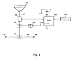
- Fig. 1 is a diagram showing the construction of an electrically-driven power steering device.
- the electrically-driven power steering device is equipped with a steering wheel 100 for steering, a steering shaft 101 fixed to the steering wheel 100 at one end thereof, a rack pinion mechanism 102 joined to the other end of the steering shaft 101, a torque sensor 103 that is provided to some midpoint of the steering shaft 101 and detects a steering torque applied to the steering shaft 101 by operating the steering wheel 100, and a worm wheel mechanism 105 for applying the rotational driving force of the motor 104 to the steering shaft 101 as steering assist force (steering assisting force).
- the torque sensor 103, a motor 104 and a vehicle speed sensor 107 are connected to an electric control unit (ECU) 106 of a vehicle, and ECU 106 controls the driving current of the motor 104 on the basis of the detection signals of the torque sensor 103 and the vehicle speed sensor 107.
- ECU 106 contains a motor controller P, and has a voltage boosting control function of boosting the voltage of 12V battery E to 200V at maximum and a motor driving voltage forming function of forming a driving voltage for the motor 104.
- a tie rod 108 is connected to a steering gear box 102, and tie rod ends 108, 109 to be joined to wheels (not shown) are provided to both the ends of the tie rod 108.
- ECU 106 refers to a preset table on the basis of the detection signal of the steering torque achieved from the torque sensor 103 when the steering is carried out by the steering wheel 100 and the detection signal of the vehicle speed achieved from the vehicle speed sensor 107 and applies the motor driving voltage corresponding to the detection signals to the motor 104.
- the steering assist force is applied to the steering shaft 101 by the motor 104.
- the motor driving voltage is applied to the motor 104 on the basis of the steering torque and the vehicle speed, however, the motor driving voltage may be simply formed on the basis of only the steering torque because the steering torque correlates with the vehicle speed.
- Fig. 2 is a diagram showing the circuit construction of the motor controller P.
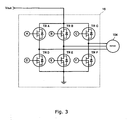
- Fig. 3 shows a motor driving circuit.
- a battery E in the vehicle is connected to the chopper circuit 13 through an ignition switch 11 and a failure detecting circuit 12.
- the chopper circuit 13 is constructed by an inductor L1, a first switching device TR1 comprising a power MOSFET, a second switching device TR2 connected to the connection point between the inductor L1 and the first switching device TR1, and a smoothing capacitor C1 connected to the output side of the second switching device TR2.
- the control terminal (gate terminal) of the switching device TR1 is connected to a controller 10.
- the failure detecting circuit 12 comprises a current detecting resistor R1 connected between the inductor L1 and the ignition switch 11, and an operation amplifier OP1 for detecting the voltage across both the ends of the resistor R1, and the output signal of the operation amplifier OP1 is input to the controller 10.
- An interrupting relay switch 14 is connected between the inductor L and the first switching device TR1, and the ON/OFF control thereof is carried out by the controller 10. Furthermore, the boosted output voltage Vout is output from the smoothing capacitor C1, and applied to the motor driving circuit 15 (see Fig. 3 ).
- the controller 10 when the ignition switch 11 is turned on, the controller 10 subjects the switching device TR1 to PWM control to thereby carry out voltage boosting control. Furthermore, the controller 10 monitors the signal from the failure detecting circuit 12. If the voltage detected by the resistor R1 is set to the magnitude corresponding to eddy current (abnormal current) in which the voltage concerned exceeds a preset value, the controller 10 regards the first switching device TR1 as suffering a short-circuiting failure, and turns off the relay switch 14, whereby the switching device is interrupted from the inductor.
- eddy current abnormal current
- the second switching element TR2 functions as a rectifying element when the energy accumulated in the inductor L1 is discharged to the smoothing capacitor C1.
- the switching device TR2 is kept to ON-state when the load is large (when large current is supplied to the motor 104 because the steering torque is large)
- a part of the current flows from the power source into the smoothing capacitor C1 at the time when the energy is accumulated into the inductor L1 (the switching device TR1 is set to ON)
- the efficiency is lowered. Therefore, in a case where the magnitude of the load is equal to a fixed value or more, the second switching device TR2 is controlled to be turned off when the first switching device TR1 is set to ON, and turned on when the first switching device TR1 is set to OFF.
- the relative rate of the switching loss of the second switching device TR2 when the energy is accumulated into the inductor L1 is increased, and thus the switching device TR2 is controlled to be perfectly set to the ON state (diode state) in order to avoid the reduction of the efficiency.
- the controller 10 refers to predetermined steering sensitive characteristic table and vehicle speed sensitive characteristic table, and outputs a PWM signal to the motor driving circuit 15 so as to achieve the steering assist force corresponding to the signals from the torque sensor 103 and the vehicle speed sensor 107.
- the motor driving circuit 15 is constructed by TRA to TRF of six power MOSFETs for driving the three-phase motor 104, and phase rotation control is carried out by the motor driving circuit 15. Since the magnitude of the motor torque can be controlled by controlling the current supply time of each power MOSFET, the control is carried out so that the steering assist force has a predetermined magnitude.
- the interrupting relay switch 14 is set to ON at the normal time.
- the chopper circuit 13 carries out the operation of boosting the voltage Vin (12V) of the battery E.
- the controller 10 controls the ON/OFF duty ratio of the switching device TR1 to a proper value (PWM control) and carries out the ON/OFF operation of the first switching device TR1.
- the failure detecting circuit 12 detects a short-circuiting failure of the switching device TR1 during the voltage boosting operation or during the stop of the operation, the controller 10 makes a judgment of abnormality, and turns off the relay switch 14. Therefore, the power supply voltage of the battery E is not boosted, and substantially directly supplied to the motor driving circuit 15 as an output voltage Vout (a voltage drop caused by the resistor R1 and the resistance component of the inductor L1 slightly exists).
- the controller 10 refers to the steering sensitive characteristic table and the vehicle speed sensitive characteristic table on the basis of the signals from the torque sensor 103 and the vehicle speed sensor 107 to form PWM signals (A) to (F), and outputs these PWM signals to the motor driving circuit 15.
- the above tables are changed at the abnormal time when the boosting operation is stopped.
- the PWM signals (A) to (F) are formed on the basis of only the steering torque.
- the steering sensitive characteristic table is referred to.
- Fig. 4 shows the steering sensitive characteristic table represented as a characteristic curve.
- the abscissa axis represents the steering torque
- the ordinate axis represents the power (power) supplied to the motor 104 by the PWM signals (A) to (F).
- a curved line A represents a characteristic curve at the normal time (when the boosting operation is carried out)
- a curved line B represents a characteristic curve at the abnormal time (when no boosting operation is carried out).
- the maximum power supplied to the motor 104 is equal to 200V x 100A.
- the PWM signals (A) to (F) are controlled so that the motor current (average value) is equal to 100A when the steering torque is maximum.
- the PWM signals (A) to (F) are controlled so that the supplied power is varied substantially like a quadratic curve between the time when the steering torque is maximum and the time when the steering torque is minimum.
- the maximum power supplied to the motor 104 is equal to 12V X 100A. That is, since no boosting operation is carried out, the PWM signals (A) to (F) are controlled so that's the voltage applied to the motor 104 is equal to the battery voltage of 12V, the motor current (average value) when the steering torque is maximum is equal to 100A, and the supplied power is smaller than the curved line A between the maximum steering torque and the minimum steering torque.
- the characteristic curve is varied between the normal time and the abnormal time in order to enhance the safety at the steering operation time. If the control is carried out like the curved line A at the abnormal time, no large problem occurs under a condition that the steering torque is small. However, in a case where a large steering torque occurs at the abnormal time, for example, in a case where abrupt steering is carried out, if the control based on the curved line A is carried out, sufficient power can not be supplied because the voltage applied to the motor is a non-boosted low voltage. In this case, an operator may pay no attention to whether abnormality occurs or not, and as a result, the operator cannot turn a steering wheel as he/she intended although the operator carries out the operation of abruptly turning the steering wheel, so that an accident may occur.
- the operator can feel the reduction of the steering assist force at the steering time irrespective of the magnitude of the steering torque, and thus the operator can be informed of the abnormal state. Accordingly, the operator can carry out steering with larger force at the abnormal time than at the normal time, and thus occurrence of an accident can be prevented.
- the right side from the center position on the abscissa axis represents the steering torque when the steering wheel is clockwise turned (+ direction), and the left side represents the steering torque when the steering wheel is counterclockwise turned.
- the characteristic curve is symmetrical bilaterally.
- the vehicle speed sensitive characteristic table is also referred to, and thus the vehicle speed is also set as a parameter in the characteristic curve of Fig. 4 . That is, plural curved lines A, B of Fig. 4 exist with respect to the vehicle speed as a parameter, and the curved line corresponding to the vehicle speed at that time is selected from these plural curved lines for the control.
- Fig. 5 shows another embodiment of the invention.
- the different point from Fig. 2 resides in that the interrupting relay switch 14 is connected between the first switching device TR1 and the ground.
- the battery voltage Vin can be directly output to the motor driving circuit 15 at the time when the boosting operation is stopped.
- a temperature sensor thermalistor element
- the breakdown of the first switching device TR1 may be judged when abnormal temperature is detected by the temperature sensor.
- a semiconductor switching device may be used for the interrupting circuit.
Landscapes
- Engineering & Computer Science (AREA)
- Chemical & Material Sciences (AREA)
- Combustion & Propulsion (AREA)
- Transportation (AREA)
- Mechanical Engineering (AREA)
- Power Steering Mechanism (AREA)
- Dc-Dc Converters (AREA)
Claims (2)
- Circuit élévateur de tension comprenant :un circuit hacheur (13) dans lequel une inductance (L1) et un dispositif de commutation (TR1) sont connectés l'un à l'autre en série etun condensateur de lissage (C1) est connecté au point de connexion entre l'inductance (L1) et le dispositif de commutation (TR1) par l'intermédiaire d'un élément redresseur (TR2) ;un circuit de détection de défaillance (12) permettant de détecter une défaillance du dispositif de commutation (TR1); et caractérisé parun circuit interrupteur (14) permettant d'interrompre le dispositif de commutation à partir de l'inductance en se basant sur la détection de la défaillance du dispositif de commutation (TR1) par le circuit de détection de défaillance (12).
- Circuit élévateur de tension comprenant :un circuit hacheur (13) dans lequel un dispositif de commutation mis à la masse (TR1) et une inductance (L1) sont connectés l'un à l'autre en série, etun condensateur de lissage (C1) est connecté au point de connexion entre le dispositif de commutation mis à la masse (TR1) et l'inductance (L1) par l'intermédiaire d'un élément redresseur (TR2) ;un circuit de détection de défaillance (12) permettant de détecter une défaillance du dispositif de commutation (TR1); et caractérisé parun circuit interrupteur (14) permettant d'interrompre le dispositif de commutation (TR1) à partir de la masse en se basant sur la détection de la défaillance du dispositif de commutation (TR1) par le circuit de détection de défaillance (12).
Applications Claiming Priority (1)
| Application Number | Priority Date | Filing Date | Title |
|---|---|---|---|
| JP2005189539A JP4172473B2 (ja) | 2005-06-29 | 2005-06-29 | 昇圧回路及び電動パワーステアリング装置 |
Publications (4)
| Publication Number | Publication Date |
|---|---|
| EP1738990A2 EP1738990A2 (fr) | 2007-01-03 |
| EP1738990A8 EP1738990A8 (fr) | 2007-04-25 |
| EP1738990A3 EP1738990A3 (fr) | 2011-03-09 |
| EP1738990B1 true EP1738990B1 (fr) | 2012-06-06 |
Family
ID=36928142
Family Applications (1)
| Application Number | Title | Priority Date | Filing Date |
|---|---|---|---|
| EP06004665A Expired - Lifetime EP1738990B1 (fr) | 2005-06-29 | 2006-03-07 | Circuit élévateur de tension et direction assistée électrique |
Country Status (5)
| Country | Link |
|---|---|
| US (1) | US7589940B2 (fr) |
| EP (1) | EP1738990B1 (fr) |
| JP (1) | JP4172473B2 (fr) |
| KR (1) | KR100729926B1 (fr) |
| CN (1) | CN1893248B (fr) |
Families Citing this family (21)
| Publication number | Priority date | Publication date | Assignee | Title |
|---|---|---|---|---|
| JP4676869B2 (ja) * | 2005-04-25 | 2011-04-27 | 本田技研工業株式会社 | 車両用電力システム及び昇圧電源 |
| JP5135819B2 (ja) * | 2007-02-19 | 2013-02-06 | 株式会社ジェイテクト | 電気式動力舵取装置 |
| KR100835194B1 (ko) * | 2007-05-29 | 2008-06-04 | 주식회사 만도 | 전동 파워스티어링 시스템의 인버터 스위치 오류 검출방법 |
| JP5153252B2 (ja) * | 2007-08-09 | 2013-02-27 | カヤバ工業株式会社 | 電動パワーステアリング装置 |
| JP5034824B2 (ja) * | 2007-09-25 | 2012-09-26 | 株式会社ジェイテクト | 電動パワーステアリング装置 |
| JP5151471B2 (ja) * | 2007-12-27 | 2013-02-27 | 株式会社ジェイテクト | 電動パワーステアリング装置 |
| CN101932488B (zh) * | 2008-01-25 | 2013-07-03 | 三菱电机株式会社 | 电动式动力转向装置 |
| JP5412768B2 (ja) * | 2008-09-02 | 2014-02-12 | 株式会社ジェイテクト | モータ制御装置及び電動パワーステアリング装置 |
| JP5284028B2 (ja) * | 2008-10-01 | 2013-09-11 | 株式会社ジェイテクト | 電動パワーステアリング装置 |
| GB0906020D0 (en) * | 2009-04-07 | 2009-05-20 | Trw Ltd | Motor drive circuitry |
| EP2435854B1 (fr) | 2009-05-28 | 2021-07-07 | Teledyne Instruments, Inc. | Canon à air numérique |
| JP2011178236A (ja) * | 2010-02-26 | 2011-09-15 | Nsk Ltd | 電源回路及びこれを用いた電動パワーステアリング装置 |
| JP5311233B2 (ja) * | 2010-12-27 | 2013-10-09 | 株式会社デンソー | モータ制御装置、および、これを用いた電動パワーステアリング装置 |
| JP5611420B1 (ja) * | 2013-06-26 | 2014-10-22 | オムロンオートモーティブエレクトロニクス株式会社 | Dc−dcコンバータ |
| JP2015008611A (ja) * | 2013-06-26 | 2015-01-15 | オムロンオートモーティブエレクトロニクス株式会社 | Dc−dcコンバータ |
| JP6168073B2 (ja) * | 2015-01-26 | 2017-07-26 | 株式会社村田製作所 | 電源装置 |
| JP6740777B2 (ja) * | 2016-07-27 | 2020-08-19 | 株式会社デンソー | 電動パワーステアリング装置 |
| DE102016117062A1 (de) * | 2016-09-12 | 2018-03-15 | HELLA GmbH & Co. KGaA | Vorrichtung zum Betreiben eines Gleichspannungswandlers |
| KR102475437B1 (ko) * | 2017-10-27 | 2022-12-06 | 엘에스오토모티브테크놀로지스 주식회사 | 컨버터 단락 방지 회로 및 이를 이용한 차량용 컨버터 |
| JP7052745B2 (ja) * | 2019-01-25 | 2022-04-12 | トヨタ自動車株式会社 | 車両制御システム |
| DE102022205740A1 (de) * | 2022-06-07 | 2023-12-07 | Robert Bosch Gesellschaft mit beschränkter Haftung | Verfahren zum Betrieb einer Ansteuervorrichtung zur Ansteuerung eines Elektromotors, insbesondere eines Lenksystems |
Family Cites Families (13)
| Publication number | Priority date | Publication date | Assignee | Title |
|---|---|---|---|---|
| JP3205651B2 (ja) | 1993-09-07 | 2001-09-04 | ティーアールダブリュ オートモーティブ ジャパン株式会社 | 電源電圧制御装置を備えた電動パワーステアリング装置 |
| US5758741A (en) | 1994-10-31 | 1998-06-02 | Jidosha Kiki Co., Ltd. | Vehicle power steering system |
| JPH11139327A (ja) | 1997-11-14 | 1999-05-25 | Honda Motor Co Ltd | 電動パワーステアリング装置 |
| JP2000118419A (ja) | 1998-10-12 | 2000-04-25 | Toyota Motor Corp | 電動式パワーステアリング装置 |
| JP3642240B2 (ja) | 1999-10-12 | 2005-04-27 | 三菱電機株式会社 | 電動式パワーステアリング装置 |
| JP3412579B2 (ja) * | 1999-10-19 | 2003-06-03 | トヨタ自動車株式会社 | 車両の電動パワーステアリング装置 |
| JP3641798B2 (ja) * | 2000-03-09 | 2005-04-27 | 三菱電機株式会社 | 車載用電流制御装置 |
| JP3805657B2 (ja) * | 2001-09-18 | 2006-08-02 | 株式会社ジェイテクト | 電動パワーステアリング装置 |
| JP4089367B2 (ja) * | 2002-09-17 | 2008-05-28 | 株式会社ジェイテクト | 電動パワーステアリング装置 |
| JP4241027B2 (ja) | 2002-12-24 | 2009-03-18 | パナソニック電工株式会社 | 電源装置 |
| JP4411897B2 (ja) | 2003-07-30 | 2010-02-10 | 株式会社ジェイテクト | 直流昇圧回路の故障判定装置 |
| JP2005117784A (ja) * | 2003-10-08 | 2005-04-28 | Rohm Co Ltd | スイッチング電源装置 |
| JP4016976B2 (ja) | 2004-08-19 | 2007-12-05 | 日本精工株式会社 | 電動パワーステアリング装置の制御装置 |
-
2005
- 2005-06-29 JP JP2005189539A patent/JP4172473B2/ja not_active Expired - Fee Related
-
2006
- 2006-03-07 EP EP06004665A patent/EP1738990B1/fr not_active Expired - Lifetime
- 2006-03-21 US US11/385,974 patent/US7589940B2/en not_active Expired - Fee Related
- 2006-04-19 KR KR1020060035214A patent/KR100729926B1/ko not_active Expired - Fee Related
- 2006-04-24 CN CN2006100777171A patent/CN1893248B/zh not_active Expired - Fee Related
Also Published As
| Publication number | Publication date |
|---|---|
| JP4172473B2 (ja) | 2008-10-29 |
| EP1738990A3 (fr) | 2011-03-09 |
| EP1738990A8 (fr) | 2007-04-25 |
| KR100729926B1 (ko) | 2007-06-18 |
| US20070000718A1 (en) | 2007-01-04 |
| US7589940B2 (en) | 2009-09-15 |
| EP1738990A2 (fr) | 2007-01-03 |
| KR20070001790A (ko) | 2007-01-04 |
| CN1893248A (zh) | 2007-01-10 |
| CN1893248B (zh) | 2010-06-16 |
| JP2007008257A (ja) | 2007-01-18 |
Similar Documents
| Publication | Publication Date | Title |
|---|---|---|
| EP1738990B1 (fr) | Circuit élévateur de tension et direction assistée électrique | |
| JP4333646B2 (ja) | 電動パワーステアリング装置 | |
| JP3518944B2 (ja) | モータ駆動装置 | |
| EP2226237B1 (fr) | Dispositif de servodirection à entraînement électrique | |
| EP2301822B1 (fr) | Système de direction assistée électrique | |
| EP0919450A1 (fr) | Dispositif de direction assistee entraine par un moteur electrique | |
| EP2746136B1 (fr) | Appareil de direction assistée électrique | |
| JP3884909B2 (ja) | 電気車及びその制御装置 | |
| JP5136283B2 (ja) | 電動パワーステアリング装置 | |
| JP4449832B2 (ja) | 電動パワーステアリング装置 | |
| US20140229066A1 (en) | Electronic control device for electric power steering apparatus | |
| CN113365901B (zh) | 用于将机电式机动车辆动力转向系统的多相电动马达与直流电压源断开连接的方法及用于控制电动马达的控制单元 | |
| CN1972180A (zh) | 通信系统 | |
| WO2023204081A1 (fr) | Dispositif d'attaque de charge | |
| EP1720238A1 (fr) | Dispositif de prévention de l'adhérence d'un relais et dispositif d'entrainement par moteur | |
| JP4351924B2 (ja) | 車載用モータ制御装置及びパワーステアリング装置。 | |
| US20050168904A1 (en) | Electronic control system having power source relay fusion detecting circuit | |
| JP5125432B2 (ja) | 電動パワーステアリング装置の制御装置及びモータの制御装置 | |
| KR100330447B1 (ko) | 전동 파워 스티어링 회로 | |
| US20210273597A1 (en) | Protective device for a semiconductor switch of an electric motor of an electromechanical motor vehicle steering system | |
| WO2026053626A1 (fr) | Dispositif d'alimentation électrique et procédé d'alimentation électrique | |
| WO2025154117A1 (fr) | Dispositif d'alimentation électrique de véhicule et procédé de détection d'anomalie pour dispositif d'alimentation électrique de véhicule | |
| KR102310535B1 (ko) | 씨디씨 시스템의 댐퍼 제어 장치 | |
| JP5034856B2 (ja) | 電動パワーステアリング装置 |
Legal Events
| Date | Code | Title | Description |
|---|---|---|---|
| PUAI | Public reference made under article 153(3) epc to a published international application that has entered the european phase |
Free format text: ORIGINAL CODE: 0009012 |
|
| AK | Designated contracting states |
Kind code of ref document: A2 Designated state(s): AT BE BG CH CY CZ DE DK EE ES FI FR GB GR HU IE IS IT LI LT LU LV MC NL PL PT RO SE SI SK TR |
|
| AX | Request for extension of the european patent |
Extension state: AL BA HR MK YU |
|
| RIN1 | Information on inventor provided before grant (corrected) |
Inventor name: GUNJI, KEITA C/O OMRON CORPORATION Inventor name: SAWANO, TAKAMOTO C/O OMRON CORPORATION |
|
| RIN1 | Information on inventor provided before grant (corrected) |
Inventor name: SAWANO, TAKAMOTOC/O OMRON CORPORATION Inventor name: GUNJI, KEITAC/O OMRON CORPORATION |
|
| RIN1 | Information on inventor provided before grant (corrected) |
Inventor name: GUNJI, KEITAC/O OMRON CORPORATION Inventor name: SAWANO, TAKAMOTOC/O OMRON CORPORATION |
|
| RAP1 | Party data changed (applicant data changed or rights of an application transferred) |
Owner name: OMRON AUTOMOTIVE ELECTRONICS CO., LTD. |
|
| PUAL | Search report despatched |
Free format text: ORIGINAL CODE: 0009013 |
|
| AK | Designated contracting states |
Kind code of ref document: A3 Designated state(s): AT BE BG CH CY CZ DE DK EE ES FI FR GB GR HU IE IS IT LI LT LU LV MC NL PL PT RO SE SI SK TR |
|
| AX | Request for extension of the european patent |
Extension state: AL BA HR MK YU |
|
| 17P | Request for examination filed |
Effective date: 20110909 |
|
| AKX | Designation fees paid |
Designated state(s): DE FR |
|
| GRAP | Despatch of communication of intention to grant a patent |
Free format text: ORIGINAL CODE: EPIDOSNIGR1 |
|
| GRAS | Grant fee paid |
Free format text: ORIGINAL CODE: EPIDOSNIGR3 |
|
| GRAA | (expected) grant |
Free format text: ORIGINAL CODE: 0009210 |
|
| AK | Designated contracting states |
Kind code of ref document: B1 Designated state(s): DE FR |
|
| REG | Reference to a national code |
Ref country code: DE Ref legal event code: R096 Ref document number: 602006029887 Country of ref document: DE Effective date: 20120802 |
|
| REG | Reference to a national code |
Ref country code: DE Ref legal event code: R082 Ref document number: 602006029887 Country of ref document: DE Representative=s name: KILIAN KILIAN & PARTNER, DE Ref country code: DE Ref legal event code: R082 Ref document number: 602006029887 Country of ref document: DE Representative=s name: KILIAN KILIAN & PARTNER MBB PATENTANWAELTE, DE |
|
| PLBE | No opposition filed within time limit |
Free format text: ORIGINAL CODE: 0009261 |
|
| STAA | Information on the status of an ep patent application or granted ep patent |
Free format text: STATUS: NO OPPOSITION FILED WITHIN TIME LIMIT |
|
| 26N | No opposition filed |
Effective date: 20130307 |
|
| REG | Reference to a national code |
Ref country code: DE Ref legal event code: R097 Ref document number: 602006029887 Country of ref document: DE Effective date: 20130307 |
|
| REG | Reference to a national code |
Ref country code: FR Ref legal event code: ST Effective date: 20131129 |
|
| PG25 | Lapsed in a contracting state [announced via postgrant information from national office to epo] |
Ref country code: FR Free format text: LAPSE BECAUSE OF NON-PAYMENT OF DUE FEES Effective date: 20130402 |
|
| REG | Reference to a national code |
Ref country code: DE Ref legal event code: R084 Ref document number: 602006029887 Country of ref document: DE Effective date: 20140717 |
|
| PGFP | Annual fee paid to national office [announced via postgrant information from national office to epo] |
Ref country code: DE Payment date: 20230131 Year of fee payment: 18 |
|
| REG | Reference to a national code |
Ref country code: DE Ref legal event code: R119 Ref document number: 602006029887 Country of ref document: DE |
|
| PG25 | Lapsed in a contracting state [announced via postgrant information from national office to epo] |
Ref country code: DE Free format text: LAPSE BECAUSE OF NON-PAYMENT OF DUE FEES Effective date: 20241001 |
|
| PG25 | Lapsed in a contracting state [announced via postgrant information from national office to epo] |
Ref country code: DE Free format text: LAPSE BECAUSE OF NON-PAYMENT OF DUE FEES Effective date: 20241001 |