EP1739342A2 - Lampadaire - Google Patents
Lampadaire Download PDFInfo
- Publication number
- EP1739342A2 EP1739342A2 EP06013673A EP06013673A EP1739342A2 EP 1739342 A2 EP1739342 A2 EP 1739342A2 EP 06013673 A EP06013673 A EP 06013673A EP 06013673 A EP06013673 A EP 06013673A EP 1739342 A2 EP1739342 A2 EP 1739342A2
- Authority
- EP
- European Patent Office
- Prior art keywords
- lamp
- light
- head
- floor
- lamp according
- Prior art date
- Legal status (The legal status is an assumption and is not a legal conclusion. Google has not performed a legal analysis and makes no representation as to the accuracy of the status listed.)
- Granted
Links
- 229920006328 Styrofoam Polymers 0.000 description 3
- 238000005286 illumination Methods 0.000 description 3
- 238000009434 installation Methods 0.000 description 3
- 239000008261 styrofoam Substances 0.000 description 3
- 238000004806 packaging method and process Methods 0.000 description 2
- 230000001419 dependent effect Effects 0.000 description 1
- 238000011161 development Methods 0.000 description 1
- 230000018109 developmental process Effects 0.000 description 1
- 230000000694 effects Effects 0.000 description 1
- 230000004313 glare Effects 0.000 description 1
- 239000000463 material Substances 0.000 description 1
Images



Classifications
-
- F—MECHANICAL ENGINEERING; LIGHTING; HEATING; WEAPONS; BLASTING
- F21—LIGHTING
- F21V—FUNCTIONAL FEATURES OR DETAILS OF LIGHTING DEVICES OR SYSTEMS THEREOF; STRUCTURAL COMBINATIONS OF LIGHTING DEVICES WITH OTHER ARTICLES, NOT OTHERWISE PROVIDED FOR
- F21V17/00—Fastening of component parts of lighting devices, e.g. shades, globes, refractors, reflectors, filters, screens, grids or protective cages
- F21V17/007—Fastening of component parts of lighting devices, e.g. shades, globes, refractors, reflectors, filters, screens, grids or protective cages with provision for shipment or storage
-
- F—MECHANICAL ENGINEERING; LIGHTING; HEATING; WEAPONS; BLASTING
- F21—LIGHTING
- F21S—NON-PORTABLE LIGHTING DEVICES; SYSTEMS THEREOF; VEHICLE LIGHTING DEVICES SPECIALLY ADAPTED FOR VEHICLE EXTERIORS
- F21S6/00—Lighting devices intended to be free-standing
- F21S6/002—Table lamps, e.g. for ambient lighting
- F21S6/003—Table lamps, e.g. for ambient lighting for task lighting, e.g. for reading or desk work, e.g. angle poise lamps
-
- F—MECHANICAL ENGINEERING; LIGHTING; HEATING; WEAPONS; BLASTING
- F21—LIGHTING
- F21V—FUNCTIONAL FEATURES OR DETAILS OF LIGHTING DEVICES OR SYSTEMS THEREOF; STRUCTURAL COMBINATIONS OF LIGHTING DEVICES WITH OTHER ARTICLES, NOT OTHERWISE PROVIDED FOR
- F21V21/00—Supporting, suspending, or attaching arrangements for lighting devices; Hand grips
- F21V21/10—Pendants, arms, or standards; Fixing lighting devices to pendants, arms, or standards
- F21V21/116—Fixing lighting devices to arms or standards
-
- F—MECHANICAL ENGINEERING; LIGHTING; HEATING; WEAPONS; BLASTING
- F21—LIGHTING
- F21Y—INDEXING SCHEME ASSOCIATED WITH SUBCLASSES F21K, F21L, F21S and F21V, RELATING TO THE FORM OR THE KIND OF THE LIGHT SOURCES OR OF THE COLOUR OF THE LIGHT EMITTED
- F21Y2103/00—Elongate light sources, e.g. fluorescent tubes
Definitions
- the present invention relates to a floor lamp according to the preamble of claim 1, which has a lamp base upwardly extending light column, on which at least one provided for holding a light source lamp head is arranged.
- Floor lamps of this type are often used, since they can be used for flexible illumination of rooms, especially office space.
- the ability to easily change the position of a floor lamp, the lighting can be adapted in a simple and fast way to different circumstances, which is a big advantage over permanently installed on a ceiling luminaires.
- Modern floor lamps are designed such that the light emitted by them is comparable in terms of its light distribution with the light of fixed to a ceiling lights installed.
- Floor lamps of this type described usually initially have a so-called.
- Light column which extends from a lamp base from substantially vertically upwards.
- at least one lamp head is arranged, which contains the light source.
- the lamp heads are usually elongated, as elongated light sources such.
- B. gas discharge lamps, in particular fluorescent tubes, are arranged.
- the lamp head is in this case substantially horizontal, that is arranged perpendicular to the lamp column, so that the light emitted from the gas discharge lamp light can be radiated uniformly towards the bottom.
- the lamp heads usually also have light influencing means in the form of grids or the like in order to allow glare-free illumination.
- the horizontal orientation of the lamp head compared to the light column requires that the lamp in the final assembly state describes approximately the shape of an L or T.
- the lamp heads are usually packaged separately from the light column.
- the luminaire head must then be mounted on the light column.
- the wiring between the lamp and the electrical components of the luminaire must be ensured to allow proper operation.
- the present invention is based on the object, such a floor lamp of the type described above to develop and improve that on the one hand, a simple transport of the lamp and on the other hand a simple and fast to be performed final assembly is possible.
- the solution according to the invention is based on the idea of attaching the luminaire head to the luminaire column in such a way that it can be moved from a transport position, in which it is arranged substantially parallel to the luminaire column, into an operating position in which it is oriented substantially horizontally, preferably rotatable - and can be locked in this operating position.
- the transport of the lamp is greatly simplified, since in this case the lamp head is oriented such that the common element consisting of light column and lamp head takes up little space.
- the combination consisting of light column and lamp head can thus be packaged and transported in a simple manner.
- the final assembly of the floor lamp according to the invention is considerably simplified, since for this purpose the lamp head can be easily pivoted from the transport position to the operating position and must be locked there.
- the particular advantage of this solution is that the wiring for the power supply of the arranged in the lamp head light source (s) already at the factory, so before sending the lamp can be done. A buyer of the lamp does not have to make the final wiring consuming.
- the luminaire according to the invention can also be mounted in a simple manner by persons who are not familiar with the production of electrical connections.
- the inventive holder of the lamp head to the light column is preferably carried out by means of a pivot bearing, which may in particular comprise a bearing sleeve, via which the lamp head is connected to the light column.
- the wiring for the power supply of the lamp head can then be performed in a simple manner by the bearing sleeve, so that the outer casing of the luminaire extending lines are avoided.
- the locking of the lamp head is preferably carried out by means of a screw connection, in particular by means of two screw connections, which are arranged on both sides of the pivot bearing.
- the screw connections may each comprise one arranged on the lamp head screw, which cooperates with a mother located on the light column.
- the screws are preferably secured by means of a fuse element to the lamp head, so that they can be pre-positioned in the packaging of the lamp in a suitable manner and accordingly need only be tightened for the final assembly of the lamp.
- the lamp head can be configured in a classical manner as described above and in particular elongated, wherein at least one socket for holding an elongate light source, in particular a gas discharge lamp, is then arranged inside the lamp head. Furthermore, the lamp head can have a light influencing element for influencing the light emitted by the light source, wherein the light influencing element can be formed in particular by a cell grid.
- Floor lamps of the generic type are often also designed such that they also allow a certain indirect lighting in addition to the direct light emission.
- This option is also in the lamp according to the present invention, in which case the lamp head is then designed such that it - in the operating position - allows on its upper side a light output.
- the lamp head on its upper side for example, have a transparent cover.
- Operating devices for operating the light source located in the light source are preferably arranged within the light column, since they can be stored in a particularly secure manner.
- the wiring from the operating device to the lamp socket takes place - as already mentioned - preferably through the rotary bearing.
- the lamp according to the invention has a total of two lamp heads, which are arranged on both sides of the light column.
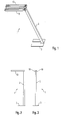
- the floor lamp according to the invention generally provided with the reference numeral 1 is shown in a perspective view, while on the other hand, Figs. 2 and 3 show side views of the lamp 1.
- the luminaire 1 according to the invention has an elongated and in the erected state substantially vertically aligned luminous column 2, which is formed by a profile body.
- the light column 2 is attached to a lamp base 3, which has a U-shape in the illustrated embodiment, but could also be configured otherwise.
- two lamp heads 10 are arranged, which are fastened to both sides of the light column 2.
- elongate light sources are respectively arranged within the lamp heads 10, the light of which is emitted by a light influencing element located in the lamp head 10 toward the bottom side.
- the lamp heads 10 are also designed in such a way that part of the light emitted by the light sources is emitted to the top. In this way, an additional indirect lighting is made possible because the light from the light sources is also thrown onto the ceiling of a room in which the floor lamp is located, where it is diffusely reflected.
- FIG. 1 to 3 illustrates that the lamp heads 10 are aligned horizontally, that are arranged in the illustrated assembly end position substantially perpendicular to the vertically oriented light column 2. A transport of this lamp 1 in this state is of course not useful, since the combination of column 2 and lamp heads 10 would take too much space.
- the luminaire heads have been packed separately from the light column in floor lamps of the type shown. Only at the final assembly of the lamp then the lamp heads were attached to the column. The effort for this was relatively high, since after the attachment of the lamp heads on the column in addition also the wiring for the light heads located in the lamp heads had to be made.
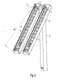
- the solution according to the invention is that the lamp heads 10 are fixed to the light column 2 so that it can be moved between a transport position, which is shown in Fig. 4, and an operating position, which is shown in Fig. 5.
- a special feature of the operating position is that the lamp heads 10 are aligned substantially parallel to the light column 2.
- the arrangement consisting of light column 2 and lamp heads 10 takes in this position significantly less space, so that this arrangement can be easily packaged and transported as a unit.
- a lamp holder 11 for holding an elongated light source 12, in particular a fluorescent lamp is disposed within each lamp head 10.
- the light of this fluorescent lamp 12 is intended to be radiated towards the bottom, for which purpose a light-influencing element in the form of a cell grid 13 is arranged within the lamp heads 10.
- the cell grid 13 consists of a body 14 consisting of a reflective material, which has a plurality of longitudinally successively arranged openings 15, via which the light emitted by the light sources to the bottom can be delivered. Since the side walls of the openings 15 have a certain thickness, it is ensured that the light is emitted only in certain angular ranges towards the bottom.
- the lamp heads 10 are also designed for indirect lighting by allowing the upper side an additional light emission.
- the lamp heads on a transparent cover 16, which is shown in Fig. 5 only on the lower lamp head 10.
- the cover 16 is attached to the opaque side walls 10a and 10b of the lamp heads 10.
- the lamp heads are each terminated by a transparent closing part 17, which is designed angularly and also an end portion of the inner side wall 10a of the lamp head 10 overlaps.
- the transfer of the lamp heads 10 from the transport position to the operating position is preferably achieved in that the lamp heads 10 are pivotally mounted about an axis perpendicular to the longitudinal axis of the light column 2 extending axis.
- This is made possible by means of a rotary bearing 20, which connects the light column 2 each with a lamp head 10.
- the pivot bearing essentially a cylindrical bearing sleeve 21, which on the one hand an opening in the wall of the light column 2 and on the other hand, an opening in the inner side wall 10a of the Lamp head 10 and the transparent end part 17 passes through.
- the bearing sleeve 21 is secured by means of a retaining ring 22 on the light column 2.
- a plurality of screw connections are provided for this purpose, which in each case have a screw 25 located on the lamp head 10 and a nut 30 cooperating with this screw 25 and located on the light column 2.
- the screws 25 are each formed by cylinder head bolts with a hexagon socket, the nuts 30 are formed by rivet nuts.
- the installation of the lamp is further simplified in that the cylinder head screws 25 are already pre-assembled in the lamp heads 10. In order to prevent unintentional falling out of the preassembled screws 25, they are secured by means of lock washers 26 and securing elements in the form of captive 27. After pivoting the lamp heads 10 in the operating position, the screws 25 must therefore only be tightened to effect a locking of the lamp heads 10 of this position. In this way, a particularly simple installation of the lamp 1 is made possible.
- FIG. 4 shows, for example, the arrangement of a lamp operating device in the form of an electronic ballast 8, which can be connected in a simple manner to the lamp sockets 11. It is essential that the connection remains permanently and regardless of whether the lamp heads 10 are in the transport position or in the operating position.
- FIGS. 6 to 11 show the individual steps when unpacking and mounting the lamp.
- Fig. 6 shows first, the arrangement of the assembly consisting of light column 2 and lamp heads 10 during transport, was dispensed with the presentation of the outer packaging.
- the arrangement is kept very compact due to the parallel orientation of the lamp heads 10 to the light column 2 and can be safely stored with the help of three Styrofoam elements 40, 41 and 42 within a carton.
- the light column 2 can be attached to the separately supplied lamp base 3, which is done by means of four screws 5, by means of which the column 2 is attached to the foot 3.
- the two further Styrofoam elements 40 and 41 are removed, whereupon then the lamp heads - as shown in Fig. 9 - by about 90 ° from the transport position in the perpendicular to the light column 2 oriented operating position about the axis of rotation I. be pivoted.
- the locking of the lamp heads 10 takes place in this operating position then by the previously described tightening the two screws 25, which are respectively arranged on both sides of a pivot bearing 20. Finally, as shown in FIG. 11, the light sources 12 are inserted into the lamp sockets 11. The lamp heads 10 can then be closed at their top with a - not shown - transparent cover over which the indirect lighting is achieved.
- the assembly consisting of light column and lamp heads in the transport position is very compact, so that a simple transport of the lamp elements is possible.
Landscapes
- Engineering & Computer Science (AREA)
- General Engineering & Computer Science (AREA)
- Non-Portable Lighting Devices Or Systems Thereof (AREA)
- Lighting Device Outwards From Vehicle And Optical Signal (AREA)
Applications Claiming Priority (1)
| Application Number | Priority Date | Filing Date | Title |
|---|---|---|---|
| DE202005010313U DE202005010313U1 (de) | 2005-06-30 | 2005-06-30 | Stehleuchte mit Leuchtenkopf |
Publications (3)
| Publication Number | Publication Date |
|---|---|
| EP1739342A2 true EP1739342A2 (fr) | 2007-01-03 |
| EP1739342A3 EP1739342A3 (fr) | 2008-01-09 |
| EP1739342B1 EP1739342B1 (fr) | 2009-10-14 |
Family
ID=37224534
Family Applications (1)
| Application Number | Title | Priority Date | Filing Date |
|---|---|---|---|
| EP06013673A Not-in-force EP1739342B1 (fr) | 2005-06-30 | 2006-06-30 | Lampadaire |
Country Status (3)
| Country | Link |
|---|---|
| EP (1) | EP1739342B1 (fr) |
| AT (1) | ATE445806T1 (fr) |
| DE (2) | DE202005010313U1 (fr) |
Cited By (4)
| Publication number | Priority date | Publication date | Assignee | Title |
|---|---|---|---|---|
| EP2077417A1 (fr) * | 2007-12-19 | 2009-07-08 | Prodisc Technology Inc. | Structure de lampe pliable biaxiale |
| US20150152998A1 (en) * | 2013-12-02 | 2015-06-04 | Air Systems, Inc. Dba Air Systems International, Inc. | Collapsible portable stand with telescoping support and integral storage case |
| US20150330558A1 (en) * | 2008-05-15 | 2015-11-19 | Air Systems, Inc. Dba Air Systems International, Inc. | Integrated portable stand, power supply, and control panel |
| US20170114968A1 (en) * | 2014-06-02 | 2017-04-27 | Quarkstar Llc | Illumination System With Multiple Light Guide Luminaire Modules |
Families Citing this family (1)
| Publication number | Priority date | Publication date | Assignee | Title |
|---|---|---|---|---|
| DE202020103721U1 (de) * | 2020-06-29 | 2021-10-04 | Zumtobel Lighting Gmbh | Stehleuchte |
Family Cites Families (17)
| Publication number | Priority date | Publication date | Assignee | Title |
|---|---|---|---|---|
| DE1754997U (de) * | 1957-05-29 | 1957-10-31 | Edwin Kirsch | Beleuchtungsstativ. |
| US3089028A (en) * | 1961-03-23 | 1963-05-07 | Golda G Klampferer | Stand with adjustably mounted head |
| GB2029952B (en) * | 1978-08-26 | 1982-08-25 | Terry J V | Adjustable lamps |
| NL8700348A (nl) * | 1987-02-13 | 1988-09-01 | Philips Nv | Bestralingsapparaat. |
| IT8709490A0 (it) * | 1987-09-22 | 1987-09-22 | Peisa Srl | Articolazione cilindrica a frizione |
| DE8807101U1 (de) * | 1988-05-31 | 1988-07-21 | Bodner, Wolfmichael, Dipl.-Designer, 3300 Braunschweig | Mehrzweckleuchte |
| WO1992007219A1 (fr) * | 1990-10-22 | 1992-04-30 | Paul Kenneth Quinn | Systeme de support reglable pour une rampe de lampes ou de lumieres |
| DE9307373U1 (de) * | 1993-05-14 | 1994-09-22 | Sonnleitner, Ferdinand, 40625 Düsseldorf | Niedervolt-Leuchtanlage |
| US5716126A (en) * | 1995-07-28 | 1998-02-10 | Meyer; Raymond F. | Mobile floor lamp |
| DE29617628U1 (de) * | 1996-10-10 | 1996-12-12 | Korsch, Alfred, 47918 Tönisvorst | Leuchtenanordnung |
| DE29706140U1 (de) * | 1997-04-07 | 1997-05-22 | Eickhorst & Co, 22453 Hamburg | Schwenkarmleuchte |
| DE29811184U1 (de) * | 1998-06-23 | 1998-09-24 | Hahn, Hermann, Prof. Dr.-Ing., 71065 Sindelfingen | Multikopf-Stehleuchte - überwiegend indirekt/asymetrisch - für Hochdrucklampen und Leuchtstofflampen |
| DE29919055U1 (de) * | 1999-10-29 | 2000-02-03 | Wila Leuchten Ag, Sevelen | Indirekt und direkt abstrahlende Stehleuchte |
| EP1143194A1 (fr) * | 2000-04-06 | 2001-10-10 | Belux AG | Lampadaire |
| DE20205726U1 (de) * | 2002-04-12 | 2003-08-21 | Grau, Tobias, 25462 Rellingen | Haltevorrichtung für Leuchtstofflampen mit einem Ständer |
| US6854862B1 (en) * | 2003-01-24 | 2005-02-15 | Steven L. Hopf | Adjustable light |
| DE10343533B4 (de) * | 2003-09-19 | 2007-08-09 | Bulthaup Gmbh & Co Kg | Leuchte |
-
2005
- 2005-06-30 DE DE202005010313U patent/DE202005010313U1/de not_active Expired - Lifetime
-
2006
- 2006-06-30 DE DE502006005075T patent/DE502006005075D1/de active Active
- 2006-06-30 EP EP06013673A patent/EP1739342B1/fr not_active Not-in-force
- 2006-06-30 AT AT06013673T patent/ATE445806T1/de active
Non-Patent Citations (1)
| Title |
|---|
| None |
Cited By (5)
| Publication number | Priority date | Publication date | Assignee | Title |
|---|---|---|---|---|
| EP2077417A1 (fr) * | 2007-12-19 | 2009-07-08 | Prodisc Technology Inc. | Structure de lampe pliable biaxiale |
| US20150330558A1 (en) * | 2008-05-15 | 2015-11-19 | Air Systems, Inc. Dba Air Systems International, Inc. | Integrated portable stand, power supply, and control panel |
| US20150152998A1 (en) * | 2013-12-02 | 2015-06-04 | Air Systems, Inc. Dba Air Systems International, Inc. | Collapsible portable stand with telescoping support and integral storage case |
| US20170114968A1 (en) * | 2014-06-02 | 2017-04-27 | Quarkstar Llc | Illumination System With Multiple Light Guide Luminaire Modules |
| US10281096B2 (en) * | 2014-06-02 | 2019-05-07 | Quarkstar Llc | Illumination system with multiple light guide luminaire modules |
Also Published As
| Publication number | Publication date |
|---|---|
| DE502006005075D1 (de) | 2009-11-26 |
| ATE445806T1 (de) | 2009-10-15 |
| EP1739342A3 (fr) | 2008-01-09 |
| DE202005010313U1 (de) | 2006-11-23 |
| EP1739342B1 (fr) | 2009-10-14 |
Similar Documents
| Publication | Publication Date | Title |
|---|---|---|
| EP2264358B1 (fr) | Luminaire et rampe lumineuse | |
| EP1739342B1 (fr) | Lampadaire | |
| EP0739618B1 (fr) | Unité d'alimentation pour chambres de malade | |
| WO2014000724A1 (fr) | Lampe munie d'un filetage central ayant une lumière projetée latéralement à l'axe longitudinal du filetage, dont la direction peut être réglée autour de cet axe | |
| EP0999409B1 (fr) | Appareil d'éclairage à encastrer avec une vasque de luminaire et un bras support pivotable | |
| EP2527536A1 (fr) | Barrière | |
| EP1270320B1 (fr) | Feux de véhicule, en particulier phare antibrouillard | |
| EP0551610A1 (fr) | Projecteur encastré | |
| DE102008011170B4 (de) | Scheinwerfer, insbesondere Kraftfahrzeugscheinwerfer | |
| DE9004427U1 (de) | Abstandsverstellbarer Lichtstrahler | |
| EP0663320B1 (fr) | Unité d'éclairage pour véhicule | |
| EP1612901B1 (fr) | Dispositif d' alimentation pour distribution de produits médicaux. | |
| EP4460643B1 (fr) | Ensemble ayant une fermeture à baïonnette | |
| DE19755996C2 (de) | Einbauvorrichtung für eine Deckenleuchte in eine Zwischendecke | |
| EP2696136A1 (fr) | Agencement d'éclairage | |
| DE9406388U1 (de) | Mastverbindung für eine Mastleuchte | |
| DE20013717U1 (de) | Leuchte | |
| EP2672171B1 (fr) | Lampe, notamment pour une bande lumineuse | |
| EP3633125B1 (fr) | Dispositif de poignée de porte intérieure éclairé destiné à l'actionnement d'un verrou d'une porte d'un véhicule de l'intérieur | |
| DE20010707U1 (de) | Leuchte | |
| EP1132681B1 (fr) | Système de rails de support | |
| DE69719916T2 (de) | Leuchtstofflampen-Beleuchtungseinrichtung mit drehbaren Reflektoren | |
| DE29911453U1 (de) | Leuchte | |
| EP0347700A2 (fr) | Dispositif d'éclairage | |
| EP0502435A2 (fr) | Cloison de douche avec un dispositif d'éclairage |
Legal Events
| Date | Code | Title | Description |
|---|---|---|---|
| PUAI | Public reference made under article 153(3) epc to a published international application that has entered the european phase |
Free format text: ORIGINAL CODE: 0009012 |
|
| AK | Designated contracting states |
Kind code of ref document: A2 Designated state(s): AT BE BG CH CY CZ DE DK EE ES FI FR GB GR HU IE IS IT LI LT LU LV MC NL PL PT RO SE SI SK TR |
|
| AX | Request for extension of the european patent |
Extension state: AL BA HR MK YU |
|
| RAP1 | Party data changed (applicant data changed or rights of an application transferred) |
Owner name: ZUMTOBEL LIGHTING GMBH |
|
| PUAL | Search report despatched |
Free format text: ORIGINAL CODE: 0009013 |
|
| AK | Designated contracting states |
Kind code of ref document: A3 Designated state(s): AT BE BG CH CY CZ DE DK EE ES FI FR GB GR HU IE IS IT LI LT LU LV MC NL PL PT RO SE SI SK TR |
|
| AX | Request for extension of the european patent |
Extension state: AL BA HR MK YU |
|
| 17P | Request for examination filed |
Effective date: 20080219 |
|
| 17Q | First examination report despatched |
Effective date: 20080320 |
|
| AKX | Designation fees paid |
Designated state(s): AT BE BG CH CY CZ DE DK EE ES FI FR GB GR HU IE IS IT LI LT LU LV MC NL PL PT RO SE SI SK TR |
|
| GRAP | Despatch of communication of intention to grant a patent |
Free format text: ORIGINAL CODE: EPIDOSNIGR1 |
|
| GRAS | Grant fee paid |
Free format text: ORIGINAL CODE: EPIDOSNIGR3 |
|
| GRAA | (expected) grant |
Free format text: ORIGINAL CODE: 0009210 |
|
| RAP1 | Party data changed (applicant data changed or rights of an application transferred) |
Owner name: ZUMTOBEL LIGHTING GMBH |
|
| AK | Designated contracting states |
Kind code of ref document: B1 Designated state(s): AT BE BG CH CY CZ DE DK EE ES FI FR GB GR HU IE IS IT LI LT LU LV MC NL PL PT RO SE SI SK TR |
|
| REG | Reference to a national code |
Ref country code: GB Ref legal event code: FG4D Free format text: NOT ENGLISH |
|
| REG | Reference to a national code |
Ref country code: CH Ref legal event code: EP |
|
| REG | Reference to a national code |
Ref country code: IE Ref legal event code: FG4D |
|
| REG | Reference to a national code |
Ref country code: CH Ref legal event code: NV Representative=s name: RIEDERER HASLER & PARTNER PATENTANWAELTE AG |
|
| REF | Corresponds to: |
Ref document number: 502006005075 Country of ref document: DE Date of ref document: 20091126 Kind code of ref document: P |
|
| LTIE | Lt: invalidation of european patent or patent extension |
Effective date: 20091014 |
|
| NLV1 | Nl: lapsed or annulled due to failure to fulfill the requirements of art. 29p and 29m of the patents act | ||
| PG25 | Lapsed in a contracting state [announced via postgrant information from national office to epo] |
Ref country code: LT Free format text: LAPSE BECAUSE OF FAILURE TO SUBMIT A TRANSLATION OF THE DESCRIPTION OR TO PAY THE FEE WITHIN THE PRESCRIBED TIME-LIMIT Effective date: 20091014 Ref country code: ES Free format text: LAPSE BECAUSE OF FAILURE TO SUBMIT A TRANSLATION OF THE DESCRIPTION OR TO PAY THE FEE WITHIN THE PRESCRIBED TIME-LIMIT Effective date: 20100125 Ref country code: IS Free format text: LAPSE BECAUSE OF FAILURE TO SUBMIT A TRANSLATION OF THE DESCRIPTION OR TO PAY THE FEE WITHIN THE PRESCRIBED TIME-LIMIT Effective date: 20100214 Ref country code: FI Free format text: LAPSE BECAUSE OF FAILURE TO SUBMIT A TRANSLATION OF THE DESCRIPTION OR TO PAY THE FEE WITHIN THE PRESCRIBED TIME-LIMIT Effective date: 20091014 Ref country code: SE Free format text: LAPSE BECAUSE OF FAILURE TO SUBMIT A TRANSLATION OF THE DESCRIPTION OR TO PAY THE FEE WITHIN THE PRESCRIBED TIME-LIMIT Effective date: 20091014 Ref country code: PT Free format text: LAPSE BECAUSE OF FAILURE TO SUBMIT A TRANSLATION OF THE DESCRIPTION OR TO PAY THE FEE WITHIN THE PRESCRIBED TIME-LIMIT Effective date: 20100215 |
|
| REG | Reference to a national code |
Ref country code: IE Ref legal event code: FD4D |
|
| PG25 | Lapsed in a contracting state [announced via postgrant information from national office to epo] |
Ref country code: SI Free format text: LAPSE BECAUSE OF FAILURE TO SUBMIT A TRANSLATION OF THE DESCRIPTION OR TO PAY THE FEE WITHIN THE PRESCRIBED TIME-LIMIT Effective date: 20091014 Ref country code: LV Free format text: LAPSE BECAUSE OF FAILURE TO SUBMIT A TRANSLATION OF THE DESCRIPTION OR TO PAY THE FEE WITHIN THE PRESCRIBED TIME-LIMIT Effective date: 20091014 Ref country code: PL Free format text: LAPSE BECAUSE OF FAILURE TO SUBMIT A TRANSLATION OF THE DESCRIPTION OR TO PAY THE FEE WITHIN THE PRESCRIBED TIME-LIMIT Effective date: 20091014 |
|
| PG25 | Lapsed in a contracting state [announced via postgrant information from national office to epo] |
Ref country code: DK Free format text: LAPSE BECAUSE OF FAILURE TO SUBMIT A TRANSLATION OF THE DESCRIPTION OR TO PAY THE FEE WITHIN THE PRESCRIBED TIME-LIMIT Effective date: 20091014 Ref country code: BG Free format text: LAPSE BECAUSE OF FAILURE TO SUBMIT A TRANSLATION OF THE DESCRIPTION OR TO PAY THE FEE WITHIN THE PRESCRIBED TIME-LIMIT Effective date: 20100114 Ref country code: RO Free format text: LAPSE BECAUSE OF FAILURE TO SUBMIT A TRANSLATION OF THE DESCRIPTION OR TO PAY THE FEE WITHIN THE PRESCRIBED TIME-LIMIT Effective date: 20091014 Ref country code: EE Free format text: LAPSE BECAUSE OF FAILURE TO SUBMIT A TRANSLATION OF THE DESCRIPTION OR TO PAY THE FEE WITHIN THE PRESCRIBED TIME-LIMIT Effective date: 20091014 Ref country code: IE Free format text: LAPSE BECAUSE OF FAILURE TO SUBMIT A TRANSLATION OF THE DESCRIPTION OR TO PAY THE FEE WITHIN THE PRESCRIBED TIME-LIMIT Effective date: 20091014 |
|
| PLBE | No opposition filed within time limit |
Free format text: ORIGINAL CODE: 0009261 |
|
| STAA | Information on the status of an ep patent application or granted ep patent |
Free format text: STATUS: NO OPPOSITION FILED WITHIN TIME LIMIT |
|
| PG25 | Lapsed in a contracting state [announced via postgrant information from national office to epo] |
Ref country code: CZ Free format text: LAPSE BECAUSE OF FAILURE TO SUBMIT A TRANSLATION OF THE DESCRIPTION OR TO PAY THE FEE WITHIN THE PRESCRIBED TIME-LIMIT Effective date: 20091014 Ref country code: SK Free format text: LAPSE BECAUSE OF FAILURE TO SUBMIT A TRANSLATION OF THE DESCRIPTION OR TO PAY THE FEE WITHIN THE PRESCRIBED TIME-LIMIT Effective date: 20091014 |
|
| 26N | No opposition filed |
Effective date: 20100715 |
|
| PG25 | Lapsed in a contracting state [announced via postgrant information from national office to epo] |
Ref country code: GR Free format text: LAPSE BECAUSE OF FAILURE TO SUBMIT A TRANSLATION OF THE DESCRIPTION OR TO PAY THE FEE WITHIN THE PRESCRIBED TIME-LIMIT Effective date: 20100115 |
|
| BERE | Be: lapsed |
Owner name: ZUMTOBEL LIGHTING G.M.B.H. Effective date: 20100630 |
|
| PG25 | Lapsed in a contracting state [announced via postgrant information from national office to epo] |
Ref country code: MC Free format text: LAPSE BECAUSE OF NON-PAYMENT OF DUE FEES Effective date: 20100630 |
|
| GBPC | Gb: european patent ceased through non-payment of renewal fee |
Effective date: 20100630 |
|
| REG | Reference to a national code |
Ref country code: FR Ref legal event code: ST Effective date: 20110228 |
|
| PG25 | Lapsed in a contracting state [announced via postgrant information from national office to epo] |
Ref country code: IT Free format text: LAPSE BECAUSE OF FAILURE TO SUBMIT A TRANSLATION OF THE DESCRIPTION OR TO PAY THE FEE WITHIN THE PRESCRIBED TIME-LIMIT Effective date: 20091014 |
|
| PG25 | Lapsed in a contracting state [announced via postgrant information from national office to epo] |
Ref country code: FR Free format text: LAPSE BECAUSE OF NON-PAYMENT OF DUE FEES Effective date: 20100630 |
|
| PG25 | Lapsed in a contracting state [announced via postgrant information from national office to epo] |
Ref country code: BE Free format text: LAPSE BECAUSE OF NON-PAYMENT OF DUE FEES Effective date: 20100630 |
|
| PG25 | Lapsed in a contracting state [announced via postgrant information from national office to epo] |
Ref country code: GB Free format text: LAPSE BECAUSE OF NON-PAYMENT OF DUE FEES Effective date: 20100630 |
|
| PG25 | Lapsed in a contracting state [announced via postgrant information from national office to epo] |
Ref country code: CY Free format text: LAPSE BECAUSE OF FAILURE TO SUBMIT A TRANSLATION OF THE DESCRIPTION OR TO PAY THE FEE WITHIN THE PRESCRIBED TIME-LIMIT Effective date: 20091014 |
|
| PG25 | Lapsed in a contracting state [announced via postgrant information from national office to epo] |
Ref country code: HU Free format text: LAPSE BECAUSE OF FAILURE TO SUBMIT A TRANSLATION OF THE DESCRIPTION OR TO PAY THE FEE WITHIN THE PRESCRIBED TIME-LIMIT Effective date: 20100415 Ref country code: LU Free format text: LAPSE BECAUSE OF NON-PAYMENT OF DUE FEES Effective date: 20100630 Ref country code: NL Free format text: LAPSE BECAUSE OF FAILURE TO SUBMIT A TRANSLATION OF THE DESCRIPTION OR TO PAY THE FEE WITHIN THE PRESCRIBED TIME-LIMIT Effective date: 20091014 |
|
| PG25 | Lapsed in a contracting state [announced via postgrant information from national office to epo] |
Ref country code: TR Free format text: LAPSE BECAUSE OF FAILURE TO SUBMIT A TRANSLATION OF THE DESCRIPTION OR TO PAY THE FEE WITHIN THE PRESCRIBED TIME-LIMIT Effective date: 20091014 |
|
| PGFP | Annual fee paid to national office [announced via postgrant information from national office to epo] |
Ref country code: CH Payment date: 20150623 Year of fee payment: 10 |
|
| PGFP | Annual fee paid to national office [announced via postgrant information from national office to epo] |
Ref country code: AT Payment date: 20150626 Year of fee payment: 10 |
|
| PGFP | Annual fee paid to national office [announced via postgrant information from national office to epo] |
Ref country code: DE Payment date: 20150831 Year of fee payment: 10 |
|
| REG | Reference to a national code |
Ref country code: DE Ref legal event code: R119 Ref document number: 502006005075 Country of ref document: DE |
|
| REG | Reference to a national code |
Ref country code: CH Ref legal event code: PL |
|
| REG | Reference to a national code |
Ref country code: AT Ref legal event code: MM01 Ref document number: 445806 Country of ref document: AT Kind code of ref document: T Effective date: 20160630 |
|
| PG25 | Lapsed in a contracting state [announced via postgrant information from national office to epo] |
Ref country code: DE Free format text: LAPSE BECAUSE OF NON-PAYMENT OF DUE FEES Effective date: 20170103 Ref country code: LI Free format text: LAPSE BECAUSE OF NON-PAYMENT OF DUE FEES Effective date: 20160630 Ref country code: CH Free format text: LAPSE BECAUSE OF NON-PAYMENT OF DUE FEES Effective date: 20160630 |
|
| PG25 | Lapsed in a contracting state [announced via postgrant information from national office to epo] |
Ref country code: AT Free format text: LAPSE BECAUSE OF NON-PAYMENT OF DUE FEES Effective date: 20160630 |