EP1739367A1 - Ventilation device for climate control systems - Google Patents
Ventilation device for climate control systems Download PDFInfo
- Publication number
- EP1739367A1 EP1739367A1 EP06114727A EP06114727A EP1739367A1 EP 1739367 A1 EP1739367 A1 EP 1739367A1 EP 06114727 A EP06114727 A EP 06114727A EP 06114727 A EP06114727 A EP 06114727A EP 1739367 A1 EP1739367 A1 EP 1739367A1
- Authority
- EP
- European Patent Office
- Prior art keywords
- basket
- frame
- baskets
- floor
- holes
- Prior art date
- Legal status (The legal status is an assumption and is not a legal conclusion. Google has not performed a legal analysis and makes no representation as to the accuracy of the status listed.)
- Withdrawn
Links
Images

Classifications
-
- F—MECHANICAL ENGINEERING; LIGHTING; HEATING; WEAPONS; BLASTING
- F04—POSITIVE - DISPLACEMENT MACHINES FOR LIQUIDS; PUMPS FOR LIQUIDS OR ELASTIC FLUIDS
- F04D—NON-POSITIVE-DISPLACEMENT PUMPS
- F04D29/00—Details, component parts, or accessories
- F04D29/60—Mounting; Assembling; Disassembling
- F04D29/601—Mounting; Assembling; Disassembling specially adapted for elastic fluid pumps
-
- F—MECHANICAL ENGINEERING; LIGHTING; HEATING; WEAPONS; BLASTING
- F04—POSITIVE - DISPLACEMENT MACHINES FOR LIQUIDS; PUMPS FOR LIQUIDS OR ELASTIC FLUIDS
- F04D—NON-POSITIVE-DISPLACEMENT PUMPS
- F04D25/00—Pumping installations or systems
- F04D25/16—Combinations of two or more pumps ; Producing two or more separate gas flows
- F04D25/166—Combinations of two or more pumps ; Producing two or more separate gas flows using fans
-
- F—MECHANICAL ENGINEERING; LIGHTING; HEATING; WEAPONS; BLASTING
- F24—HEATING; RANGES; VENTILATING
- F24F—AIR-CONDITIONING; AIR-HUMIDIFICATION; VENTILATION; USE OF AIR CURRENTS FOR SCREENING
- F24F7/00—Ventilation
- F24F7/007—Ventilation with forced flow
-
- F—MECHANICAL ENGINEERING; LIGHTING; HEATING; WEAPONS; BLASTING
- F24—HEATING; RANGES; VENTILATING
- F24F—AIR-CONDITIONING; AIR-HUMIDIFICATION; VENTILATION; USE OF AIR CURRENTS FOR SCREENING
- F24F11/00—Control or safety arrangements
- F24F11/70—Control systems characterised by their outputs; Constructional details thereof
- F24F11/72—Control systems characterised by their outputs; Constructional details thereof for controlling the supply of treated air, e.g. its pressure
- F24F11/79—Control systems characterised by their outputs; Constructional details thereof for controlling the supply of treated air, e.g. its pressure for controlling the direction of the supplied air
-
- F—MECHANICAL ENGINEERING; LIGHTING; HEATING; WEAPONS; BLASTING
- F24—HEATING; RANGES; VENTILATING
- F24F—AIR-CONDITIONING; AIR-HUMIDIFICATION; VENTILATION; USE OF AIR CURRENTS FOR SCREENING
- F24F2221/00—Details or features not otherwise provided for
- F24F2221/40—HVAC with raised floors
Definitions
- the present invention relates to a ventilation device for climate control systems.
- Computer rooms, and in general any site that contains several items of electronic equipment and racks i.e., supporting frames for a plurality of electrical, electronic and similar instruments, generally enclosed within appropriately provided ventilated cabinets
- require continuous climate control suitable to prevent the heat generated by the computers and electronic instruments from accumulating, generating temperatures that are so high as to damage the internal components of the electronic instruments and the like.
- underfloor climate control systems are generally installed in computer rooms and are increasingly widespread particularly in environments provided on a raised floor.
- the interspace between the floor slab and the raised floor can in fact be equipped easily not only for the distribution of the cables for connecting and supplying power to the racks and computers but also as a plenum, i.e., as a passage space for air conditioning, said plenums conveying the air to the overlying environments by means of floor-mounted grilles.
- the transfer of the cooled air from the plenum to the environment to be climate-controlled occurs mainly by so-called displacement, a principle according to which the stratification of the air according to temperature is used and its penetration into the overlying environment is facilitated by way of the difference in relative density with respect to the warmer air that is already present in the environment.
- climate control systems for computer rooms which are capable of inducing a forced motion of the cooled air instead of leaving its diffusion to natural stratification are becoming increasingly widespread.
- these systems are provided not only with the central ventilation unit, which propels the conditioned air into the plenum under the floor, and with the floor-mounted grilles adapted to make said conditioned air flow out into the environment, but also with auxiliary ventilation units, which are arranged predominantly within the interspace between the raised floor and the floor slab, which acts as a plenum.
- auxiliary ventilation units intensify the efficiency of the central ventilation unit, reducing climate control times.
- the ventilation devices that constitute such auxiliary units are adapted to convey the conditioned air generically upward, with the risk of obtaining excessive cooling for the computers and racks that lie closer and insufficient cooling, or at least slow cooling, for the computers and racks that are located further from said devices.
- the aim of the present invention is to provide a ventilation device particularly for climate control systems installed in floors, walls, ceilings and the like, which is capable of obviating the drawbacks shown by known types of ventilation device.
- an object of the present invention is to provide a ventilation device which can optimize the distribution of the conditioned air in the environment to be climate-controlled.
- Another object of the present invention is to provide a ventilation device whose configuration can be changed easily even by a user who does not have particular prior training.
- Another object of the present invention is to provide a ventilation device which can be installed in known panel-type raised floors.
- Another object of the present invention is to provide a ventilation device which is compact and can be installed even in small interspaces between the floor slab and the raised floor.
- a further object of the present invention is to provide a ventilation device whose effectiveness and efficiency are at least equal to those of conventional devices.
- a still further object of the present invention is to provide a ventilation device particularly for climate control systems installed in floors, walls, ceilings and the like, which can be manufactured with known systems and technologies.
- a ventilation device particularly for climate control systems installed in floors, walls, ceilings and the like, characterized in that it is constituted by a supporting frame for at least one oscillating basket, which is adapted to contain at least one motorized fan for aspirating the conditioned air from a plenum with which said device is associated, said at least one oscillating basket being in turn coupled to said frame with means for the rotation of said basket about at least one axis, said basket being arrangeable with a preset inclination with respect to the arrangement of the floor, wall or ceiling in which the device is flush-mounted.
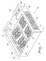
- a ventilation device particularly for climate control systems installed in floors, walls, ceilings and the like according to the invention is generally designated by the reference numeral 10.
- the device 10 is constituted by a supporting frame 11 for two oscillating baskets, respectively 12 and 13.
- Each of the two baskets 12 and 13 contains two motorized fans.
- the first basket 12 contains two first fans, which are arranged inside blowers 14 and 15, and the second basket 13 contains two second fans, each arranged inside two additional blowers 16 and 17.
- the blowers 14, 15, 16 and 17 are adapted to draw conditioned air from a plenum with which the device 10 is associated; the conditioned air reaches said plenum from a central climate control unit, which is not shown for the sake of simplicity.
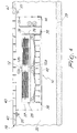
- the device 10 is recessed in a raised floor 19, in an interspace 22 between panels 42 that compose it and the floor slab 23; the interspace 22 provides the plenum for feeding conditioned air.
- Each oscillating basket 12 and 13 in turn is coupled to the frame 11 by way of means for the rotation of said basket about an axis.
- the two baskets 12 and 13 each rotate about an axis which is parallel to the rotation axis of the other basket.
- the baskets 12 and 13 therefore can be rotated and positioned with a preset inclination with respect to the plane of arrangement of the floor 19 (or wall or ceiling) in which the device 10 is recessed.
- Each basket 12 and 13 can be inclined independently with respect to the other basket 12 and 13.
- the frame 11 has lips 24 for resting on cross-members 20 of the raised floor 19 in which the device 10 is recessed, so that said device is arranged, as mentioned, in the interspace 22 between the floor 19 and the underlying surface, i.e., the floor slab 23; the interspace 22, as mentioned, forms the plenum by means of which the conditioned air reaches the device 10.
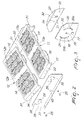
- each basket 12 and 13 are constituted by two coaxial pivots 25 and 26, as shown in Figure 4.
- the pivots 25 and 26 are adapted to couple rotatably the respective basket 12 and 13 (the first basket 12 is visible in the cross-section of Figure 4) to two supporting brackets 27 and 28, which are mutually opposite with respect to the baskets that they support.
- the brackets 27 and 28 are rigidly coupled to the supporting frame 11.
- brackets 27 and 28 are made of punch-cut and bent sheet metal and are fixed to the frame by means of additional threaded elements 36.
- Each of the pivots 25 and 26 is formed by a threaded element, which is adapted to pass through two holes 29 and 30: the first hole 29 is provided in the bracket 27 and 28, and the second hole 30 is provided in a facing connecting flap 31 of the basket 12 and 13.
- Each threaded element is screwed to a corresponding complementarily threaded locking female thread element 32.
- the female thread element 32 is fixed inside the connecting flap 31 of the basket 12 and 13.
- Each basket 12 and 13 is constituted by a cover made of sheet metal, respectively designated by the reference numerals 12a and 13a, to which the connecting flaps 31 belong; the cup-shaped bodies of the motorized blowers, respectively 14, 15, 16 and 17, hang from the covers 12a and 13a.
- the covers 12a and 13a have a grille-shaped portion 12b and 13b at each of the underlying fans.
- the means for the rotation of the baskets 12 and 13 also comprise means for maintaining the configuration on the part of the baskets 12 and 13.
- Said means for maintaining configuration are constituted by two protrusions 33 and 34, which protrude from the connecting flaps 31 with which each basket 12 and 13 is provided.
- Each protrusion 33 and 34 is adapted to be inserted reversibly in selectively one of a plurality of holes 35 arranged in a circular arc in the vicinity of the first hole 29 on the facing bracket 27 and 28.
- Reversible insertion is obtained by elastic deformation of the brackets 27 and 28 and/or the flap 31 on which the protrusions are provided.
- each connecting flap 31 has two protrusions 33 and 34, which are symmetrical with respect to the rotation axis of the basket 12 and 13 to which they belong.
- each pair of protrusions 33 and 34 can be inserted reversibly in a corresponding pair of symmetrical holes, designated by the reference numerals 35a and 35b in Figure 3 by way of example, selected among a plurality of pairs of holes.
- Said plurality of pairs of holes is formed by two arcs of holes 35, which are symmetrically mutually opposite with respect to the axis of the first hole 29, on the facing supporting bracket 27 and 28.
- Each one of the protrusions 33 and 34 is formed by a stud, which is obtained on the connecting flap 31 to which the protrusions belong, the flap 31 being made of sheet metal, like the cover 12a and 13a, on which the flaps are obtained by bending.
- the supporting frame 11 is constituted by a box-like body made of sheet metal, which is open on the side directed toward the environment to be climate-controlled.
- the box-like body is provided with intake grilles 37 and 38 for protection against the suction of any foreign objects from the plenum with which the device 10 is associated.
- the plenum is provided by the interspace 22.
- the frame 11 has a grille 37 on each of its faces 39 which lie transversely to the supporting brackets 27 and 28 and two additional grilles 38 on its bottom 40, at the two overlying baskets 12 and 13.
- the frame 11 has a substantially square shape and its dimensions are such that it can be positioned on a raised floor 19 of a per se known type instead of a panel 42, which together with other identical panels 42 composes the raised floor 19.
- the device 10 is conveniently closed in an upper region by a grille, preferably of the walkable type 43.
- the device 10 according to the invention therefore allows to orient each basket 12 and 13 according to the type of distribution of conditioned air to be obtained in the environment to be climate-controlled.
- the inclination is selected among a plurality of positions set by the number of holes 35 that constitute each arc of holes.
- the inclination is changed, after releasing the bracket 27 and 28 and the flap 31 from the grip of the threaded elements 25 and 26, by applying to the basket 12 and 13 a torque which makes the protrusions 33 and 34 slide out of the holes 35a and 35b in which they are accommodated.
- the device 10 is provided with an electric motor drive for the continuous and not stepwise rotation of each basket.
- the motor drive also comprises the means for maintaining the set configuration.
- Figures 5 to 8 each illustrate a possible distribution of the stream of conditioned air which can be obtained with a combination of configurations of the baskets 12 and 13.
- This configuration allows to obtain a greater "fountain" flow, capable therefore of providing direct cooling to regions which lie higher up from the floor 19 with respect to what the baskets 12 and 13 in the configuration of Figure 5 can do.
- the first basket 12 is parallel to the floor 19, while the second basket 13 is inclined toward the first basket 12; in this manner, the flow 50 concentrates in the region that lies above the first basket 12.
- both baskets are oriented toward one side and the flow 50 is directed toward a region which is lateral with respect to the device 10.
- Figures 5 to 8 show how the device 10 can be set up to provide climate control of different regions of the environment according to requirements, i.e., depending on where the computerized units, racks and other similar electronic units to be cooled are arranged and at what height they are located, or depending on the computerized stations of the operators working in a same open space.
- the possibility to orient the baskets 12 and 13 that characterizes the device 10 according to the invention can therefore be used also to increase the well-being, and therefore the work quality, of several operators working in a single environment, such as for example an open space.
- the device 10 is provided with a compartment 44 for accommodating a unit for controlling and managing the rotation rate of the motorized blowers 14, 15, 16 and 17.
- the device 10 is provided with suitable holes, such as the through hole 45 on the bracket 27, for the passage of the power supply cables of the motorized fans.
- the control and management unit can be interfaced with a network of identical devices 10, mutually controlled according to a configuration of the "master-slave" type.
- the devices 10 accordingly behave in the same manner.
- the control panel further allows to manage the speeds of the fans.
- the plenum is not pressurized, for an equal speed of the fans of the various devices 10 the resulting flow-rate is in fact lower than necessary.
- the advantage of being able to adjust the flow-rate of the air that flows out of each device 10 also allows energy saving, as in the case in which the racks are not filled to full capacity and the heat to be conditioned is lower than the standards of said racks when fully loaded.
- the device 10 according to the invention offers maximum flexibility in use.
- the device 10 in fact merely needs to be connected to an electric power supply, and if it is provided with a power supply cable of suitable length, it may not be indispensable to remove the plug from the socket in order to move it to another socket.
- the present invention provides a ventilation device which is capable of optimizing the distribution of the conditioned air in the environment to be climate-controlled.
- the present invention provides a ventilation device whose configuration can be changed easily even by a user who does not have particular prior training.
- the present invention provides a ventilation device which can be installed in known panel-type raised floors.
- the present invention provides a ventilation device which is compact and can also be installed in small interspaces between the floor slab and the raised floor.
- the present invention provides a ventilation device whose effectiveness and efficiency are at least equal to those of known types.
- the present invention provides a ventilation device particularly for climate control systems installed in floors, walls, ceilings and the like which can be manufactured with known systems and technologies.
- the materials employed may be any according to requirements and to the state of the art.
Landscapes
- Engineering & Computer Science (AREA)
- Mechanical Engineering (AREA)
- General Engineering & Computer Science (AREA)
- Chemical & Material Sciences (AREA)
- Combustion & Propulsion (AREA)
- Duct Arrangements (AREA)
Applications Claiming Priority (1)
| Application Number | Priority Date | Filing Date | Title |
|---|---|---|---|
| IT000196A ITPD20050196A1 (it) | 2005-06-30 | 2005-06-30 | Dispositivo di ventilazione per impianti di climatizzazione |
Publications (1)
| Publication Number | Publication Date |
|---|---|
| EP1739367A1 true EP1739367A1 (en) | 2007-01-03 |
Family
ID=36869861
Family Applications (1)
| Application Number | Title | Priority Date | Filing Date |
|---|---|---|---|
| EP06114727A Withdrawn EP1739367A1 (en) | 2005-06-30 | 2006-05-30 | Ventilation device for climate control systems |
Country Status (3)
| Country | Link |
|---|---|
| EP (1) | EP1739367A1 (it) |
| IT (1) | ITPD20050196A1 (it) |
| WO (1) | WO2007003514A1 (it) |
Cited By (6)
| Publication number | Priority date | Publication date | Assignee | Title |
|---|---|---|---|---|
| CN102486179A (zh) * | 2010-12-13 | 2012-06-06 | 杜文娟 | 模拟自然风电扇及其使用方法 |
| KR200466286Y1 (ko) * | 2012-07-17 | 2013-04-08 | 고홍달 | 열차용 냉방장치 |
| KR200466289Y1 (ko) * | 2012-07-17 | 2013-04-08 | 고홍달 | 열차용 냉방장치 |
| WO2014056671A1 (de) * | 2012-10-08 | 2014-04-17 | Ebm-Papst Mulfingen Gmbh & Co. Kg | Ventilator sowie zugehöriges trägerelement |
| WO2015189992A1 (ja) * | 2014-06-13 | 2015-12-17 | 三菱電機株式会社 | 天井埋込型空気調和機 |
| RU174399U1 (ru) * | 2015-12-11 | 2017-10-11 | Ангел Йорданов СТЕФАНОВ | Энергоэффективный вентилятор с малой мощностью |
Families Citing this family (6)
| Publication number | Priority date | Publication date | Assignee | Title |
|---|---|---|---|---|
| CN101328900A (zh) * | 2007-06-19 | 2008-12-24 | 深圳市联创实业有限公司 | 超薄型家用空气调节装置 |
| EP2666721B1 (en) * | 2012-05-24 | 2019-05-15 | Airbus Operations GmbH | Smoke detection system and method for operating a smoke detection system |
| DE202013008468U1 (de) * | 2013-09-24 | 2015-01-08 | Oerlikon Leybold Vacuum Gmbh | Vakuumpumpengehäuse |
| CN104612990B (zh) * | 2015-01-30 | 2017-04-05 | 浙江理工大学 | 一种轴流式风机风墙 |
| JP2019183691A (ja) * | 2018-04-04 | 2019-10-24 | 三菱電機株式会社 | 送風装置および送風方法 |
| JP2020172905A (ja) * | 2019-04-11 | 2020-10-22 | 三菱電機株式会社 | 送風装置 |
Citations (6)
| Publication number | Priority date | Publication date | Assignee | Title |
|---|---|---|---|---|
| EP1017263A2 (en) * | 1998-12-30 | 2000-07-05 | Edward C. Koplin | Computer cabinet design |
| US6340283B1 (en) * | 2000-08-31 | 2002-01-22 | Graves Spray Supply, Inc. | Adjustable impingement dual blower apparatus |
| JP2002223091A (ja) * | 2001-01-25 | 2002-08-09 | Matsushita Electric Ind Co Ltd | 装置架設用筐体 |
| US6557624B1 (en) * | 2000-08-09 | 2003-05-06 | Liebert Corporation | Configurable system and method for cooling a room |
| US20050019155A1 (en) * | 2003-07-25 | 2005-01-27 | Lasko William E. | Multi-directional air circulating fan |
| US20050075065A1 (en) * | 2003-09-12 | 2005-04-07 | Degree C | Intelligent networked fan assisted tiles for adaptive thermal management of thermally sensitive rooms |
-
2005
- 2005-06-30 IT IT000196A patent/ITPD20050196A1/it unknown
-
2006
- 2006-05-30 EP EP06114727A patent/EP1739367A1/en not_active Withdrawn
- 2006-06-22 WO PCT/EP2006/063445 patent/WO2007003514A1/en not_active Ceased
Patent Citations (6)
| Publication number | Priority date | Publication date | Assignee | Title |
|---|---|---|---|---|
| EP1017263A2 (en) * | 1998-12-30 | 2000-07-05 | Edward C. Koplin | Computer cabinet design |
| US6557624B1 (en) * | 2000-08-09 | 2003-05-06 | Liebert Corporation | Configurable system and method for cooling a room |
| US6340283B1 (en) * | 2000-08-31 | 2002-01-22 | Graves Spray Supply, Inc. | Adjustable impingement dual blower apparatus |
| JP2002223091A (ja) * | 2001-01-25 | 2002-08-09 | Matsushita Electric Ind Co Ltd | 装置架設用筐体 |
| US20050019155A1 (en) * | 2003-07-25 | 2005-01-27 | Lasko William E. | Multi-directional air circulating fan |
| US20050075065A1 (en) * | 2003-09-12 | 2005-04-07 | Degree C | Intelligent networked fan assisted tiles for adaptive thermal management of thermally sensitive rooms |
Non-Patent Citations (1)
| Title |
|---|
| PATENT ABSTRACTS OF JAPAN vol. 2002, no. 12 12 December 2002 (2002-12-12) * |
Cited By (10)
| Publication number | Priority date | Publication date | Assignee | Title |
|---|---|---|---|---|
| CN102486179A (zh) * | 2010-12-13 | 2012-06-06 | 杜文娟 | 模拟自然风电扇及其使用方法 |
| KR200466286Y1 (ko) * | 2012-07-17 | 2013-04-08 | 고홍달 | 열차용 냉방장치 |
| KR200466289Y1 (ko) * | 2012-07-17 | 2013-04-08 | 고홍달 | 열차용 냉방장치 |
| WO2014056671A1 (de) * | 2012-10-08 | 2014-04-17 | Ebm-Papst Mulfingen Gmbh & Co. Kg | Ventilator sowie zugehöriges trägerelement |
| CN104718379A (zh) * | 2012-10-08 | 2015-06-17 | 穆尔芬根依必派特股份有限公司 | 通风机及所属的支承件 |
| RU2604979C2 (ru) * | 2012-10-08 | 2016-12-20 | Ебм-Папст Мульфинген Гмбх Унд Ко. Кг | Вентилятор, а также соответствующий опорный элемент |
| US10060448B2 (en) | 2012-10-08 | 2018-08-28 | Ebm-Papst Mulfingen Gmbh & Co. Kg | Fan and associated support element |
| WO2015189992A1 (ja) * | 2014-06-13 | 2015-12-17 | 三菱電機株式会社 | 天井埋込型空気調和機 |
| JPWO2015189992A1 (ja) * | 2014-06-13 | 2017-04-20 | 三菱電機株式会社 | 天井埋込型空気調和機 |
| RU174399U1 (ru) * | 2015-12-11 | 2017-10-11 | Ангел Йорданов СТЕФАНОВ | Энергоэффективный вентилятор с малой мощностью |
Also Published As
| Publication number | Publication date |
|---|---|
| ITPD20050196A1 (it) | 2007-01-01 |
| WO2007003514A1 (en) | 2007-01-11 |
Similar Documents
| Publication | Publication Date | Title |
|---|---|---|
| US8640479B2 (en) | Cooling system for a room containing electronic data processing equipment | |
| CN102016431B (zh) | 除湿装置和方法 | |
| US7907402B2 (en) | Cooling system | |
| EP1739367A1 (en) | Ventilation device for climate control systems | |
| US7660117B2 (en) | Deformable duct guides that accommodate electronic connection lines | |
| US20140238639A1 (en) | Modular enclosure system and kit for containing and regulating airflow | |
| JP5855895B2 (ja) | 通信・情報処理機器室等の空調システム | |
| CN210320314U (zh) | 出风装置及设有其的换热设备 | |
| CN215001992U (zh) | 风墙系统及数据中心 | |
| JP2011179712A (ja) | 空調用床吹出し口装置 | |
| CN111447808B (zh) | 弥漫式侧向送风系统 | |
| US20090124188A1 (en) | Personal distribution terminal | |
| US20020094773A1 (en) | Cornice duct system | |
| JP4615267B2 (ja) | ファン内蔵二重床パネル及びこれを備えた室内空調システム | |
| CN112880009B (zh) | 空调器 | |
| JP6536970B2 (ja) | 空調装置 | |
| CN217884325U (zh) | 一种精准制冷送风装置 | |
| JP3188751U (ja) | 空気調和システム | |
| CN222799262U (zh) | 空调器的面板组件及空调器 | |
| JP7552186B2 (ja) | 個別空調空気吹出装置及び空調システム | |
| CN222747364U (zh) | 天花机和暖通系统 | |
| US20120052789A1 (en) | Personalized distribution terminal | |
| CN208170786U (zh) | 冷凝器机组及空调系统 | |
| CN112880008B (zh) | 空调及其控制方法 | |
| JP2016133245A (ja) | 床置き型室内空調機接続用床下チャンバ |
Legal Events
| Date | Code | Title | Description |
|---|---|---|---|
| PUAI | Public reference made under article 153(3) epc to a published international application that has entered the european phase |
Free format text: ORIGINAL CODE: 0009012 |
|
| AK | Designated contracting states |
Kind code of ref document: A1 Designated state(s): AT BE BG CH CY CZ DE DK EE ES FI FR GB GR HU IE IS IT LI LT LU LV MC NL PL PT RO SE SI SK TR |
|
| AX | Request for extension of the european patent |
Extension state: AL BA HR MK YU |
|
| 17P | Request for examination filed |
Effective date: 20070619 |
|
| 17Q | First examination report despatched |
Effective date: 20070802 |
|
| AKX | Designation fees paid |
Designated state(s): AT BE BG CH CY CZ DE DK EE ES FI FR GB GR HU IE IS IT LI LT LU LV MC NL PL PT RO SE SI SK TR |
|
| RAP1 | Party data changed (applicant data changed or rights of an application transferred) |
Owner name: EMERSON NETWORK POWER S.R.L. |
|
| STAA | Information on the status of an ep patent application or granted ep patent |
Free format text: STATUS: THE APPLICATION IS DEEMED TO BE WITHDRAWN |
|
| 18D | Application deemed to be withdrawn |
Effective date: 20121201 |