EP1740027A2 - Procédé de fabrication d'un assemblage électronique surmoulé - Google Patents
Procédé de fabrication d'un assemblage électronique surmoulé Download PDFInfo
- Publication number
- EP1740027A2 EP1740027A2 EP06076193A EP06076193A EP1740027A2 EP 1740027 A2 EP1740027 A2 EP 1740027A2 EP 06076193 A EP06076193 A EP 06076193A EP 06076193 A EP06076193 A EP 06076193A EP 1740027 A2 EP1740027 A2 EP 1740027A2
- Authority
- EP
- European Patent Office
- Prior art keywords
- substrate
- mold
- die
- backplate
- heatsink
- Prior art date
- Legal status (The legal status is an assumption and is not a legal conclusion. Google has not performed a legal analysis and makes no representation as to the accuracy of the status listed.)
- Granted
Links
Images


Classifications
-
- H—ELECTRICITY
- H10—SEMICONDUCTOR DEVICES; ELECTRIC SOLID-STATE DEVICES NOT OTHERWISE PROVIDED FOR
- H10W—GENERIC PACKAGES, INTERCONNECTIONS, CONNECTORS OR OTHER CONSTRUCTIONAL DETAILS OF DEVICES COVERED BY CLASS H10
- H10W40/00—Arrangements for thermal protection or thermal control
- H10W40/70—Fillings or auxiliary members in containers or in encapsulations for thermal protection or control
- H10W40/77—Auxiliary members characterised by their shape
- H10W40/778—Auxiliary members characterised by their shape in encapsulations
-
- B—PERFORMING OPERATIONS; TRANSPORTING
- B29—WORKING OF PLASTICS; WORKING OF SUBSTANCES IN A PLASTIC STATE IN GENERAL
- B29C—SHAPING OR JOINING OF PLASTICS; SHAPING OF MATERIAL IN A PLASTIC STATE, NOT OTHERWISE PROVIDED FOR; AFTER-TREATMENT OF THE SHAPED PRODUCTS, e.g. REPAIRING
- B29C45/00—Injection moulding, i.e. forcing the required volume of moulding material through a nozzle into a closed mould; Apparatus therefor
- B29C45/14—Injection moulding, i.e. forcing the required volume of moulding material through a nozzle into a closed mould; Apparatus therefor incorporating preformed parts or layers, e.g. injection moulding around inserts or for coating articles
- B29C45/14467—Joining articles or parts of a single article
-
- B—PERFORMING OPERATIONS; TRANSPORTING
- B29—WORKING OF PLASTICS; WORKING OF SUBSTANCES IN A PLASTIC STATE IN GENERAL
- B29C—SHAPING OR JOINING OF PLASTICS; SHAPING OF MATERIAL IN A PLASTIC STATE, NOT OTHERWISE PROVIDED FOR; AFTER-TREATMENT OF THE SHAPED PRODUCTS, e.g. REPAIRING
- B29C45/00—Injection moulding, i.e. forcing the required volume of moulding material through a nozzle into a closed mould; Apparatus therefor
- B29C45/14—Injection moulding, i.e. forcing the required volume of moulding material through a nozzle into a closed mould; Apparatus therefor incorporating preformed parts or layers, e.g. injection moulding around inserts or for coating articles
- B29C45/14639—Injection moulding, i.e. forcing the required volume of moulding material through a nozzle into a closed mould; Apparatus therefor incorporating preformed parts or layers, e.g. injection moulding around inserts or for coating articles for obtaining an insulating effect, e.g. for electrical components
- B29C45/14655—Injection moulding, i.e. forcing the required volume of moulding material through a nozzle into a closed mould; Apparatus therefor incorporating preformed parts or layers, e.g. injection moulding around inserts or for coating articles for obtaining an insulating effect, e.g. for electrical components connected to or mounted on a carrier, e.g. lead frame
-
- H—ELECTRICITY
- H05—ELECTRIC TECHNIQUES NOT OTHERWISE PROVIDED FOR
- H05K—PRINTED CIRCUITS; CASINGS OR CONSTRUCTIONAL DETAILS OF ELECTRIC APPARATUS; MANUFACTURE OF ASSEMBLAGES OF ELECTRICAL COMPONENTS
- H05K3/00—Apparatus or processes for manufacturing printed circuits
- H05K3/22—Secondary treatment of printed circuits
- H05K3/28—Applying non-metallic protective coatings
- H05K3/284—Applying non-metallic protective coatings for encapsulating mounted components
-
- H—ELECTRICITY
- H10—SEMICONDUCTOR DEVICES; ELECTRIC SOLID-STATE DEVICES NOT OTHERWISE PROVIDED FOR
- H10W—GENERIC PACKAGES, INTERCONNECTIONS, CONNECTORS OR OTHER CONSTRUCTIONAL DETAILS OF DEVICES COVERED BY CLASS H10
- H10W74/00—Encapsulations, e.g. protective coatings
- H10W74/10—Encapsulations, e.g. protective coatings characterised by their shape or disposition
- H10W74/111—Encapsulations, e.g. protective coatings characterised by their shape or disposition the semiconductor body being completely enclosed
- H10W74/114—Encapsulations, e.g. protective coatings characterised by their shape or disposition the semiconductor body being completely enclosed by a substrate and the encapsulations
-
- B—PERFORMING OPERATIONS; TRANSPORTING
- B29—WORKING OF PLASTICS; WORKING OF SUBSTANCES IN A PLASTIC STATE IN GENERAL
- B29C—SHAPING OR JOINING OF PLASTICS; SHAPING OF MATERIAL IN A PLASTIC STATE, NOT OTHERWISE PROVIDED FOR; AFTER-TREATMENT OF THE SHAPED PRODUCTS, e.g. REPAIRING
- B29C45/00—Injection moulding, i.e. forcing the required volume of moulding material through a nozzle into a closed mould; Apparatus therefor
- B29C45/14—Injection moulding, i.e. forcing the required volume of moulding material through a nozzle into a closed mould; Apparatus therefor incorporating preformed parts or layers, e.g. injection moulding around inserts or for coating articles
- B29C45/14065—Positioning or centering articles in the mould
-
- H—ELECTRICITY
- H05—ELECTRIC TECHNIQUES NOT OTHERWISE PROVIDED FOR
- H05K—PRINTED CIRCUITS; CASINGS OR CONSTRUCTIONAL DETAILS OF ELECTRIC APPARATUS; MANUFACTURE OF ASSEMBLAGES OF ELECTRICAL COMPONENTS
- H05K1/00—Printed circuits
- H05K1/02—Details
- H05K1/0201—Thermal arrangements, e.g. for cooling, heating or preventing overheating
- H05K1/0203—Cooling of mounted components
-
- H—ELECTRICITY
- H05—ELECTRIC TECHNIQUES NOT OTHERWISE PROVIDED FOR
- H05K—PRINTED CIRCUITS; CASINGS OR CONSTRUCTIONAL DETAILS OF ELECTRIC APPARATUS; MANUFACTURE OF ASSEMBLAGES OF ELECTRICAL COMPONENTS
- H05K2201/00—Indexing scheme relating to printed circuits covered by H05K1/00
- H05K2201/10—Details of components or other objects attached to or integrated in a printed circuit board
- H05K2201/10007—Types of components
- H05K2201/10189—Non-printed connector
-
- H—ELECTRICITY
- H05—ELECTRIC TECHNIQUES NOT OTHERWISE PROVIDED FOR
- H05K—PRINTED CIRCUITS; CASINGS OR CONSTRUCTIONAL DETAILS OF ELECTRIC APPARATUS; MANUFACTURE OF ASSEMBLAGES OF ELECTRICAL COMPONENTS
- H05K2201/00—Indexing scheme relating to printed circuits covered by H05K1/00
- H05K2201/10—Details of components or other objects attached to or integrated in a printed circuit board
- H05K2201/10431—Details of mounted components
- H05K2201/1056—Metal over component, i.e. metal plate over component mounted on or embedded in PCB
-
- H—ELECTRICITY
- H05—ELECTRIC TECHNIQUES NOT OTHERWISE PROVIDED FOR
- H05K—PRINTED CIRCUITS; CASINGS OR CONSTRUCTIONAL DETAILS OF ELECTRIC APPARATUS; MANUFACTURE OF ASSEMBLAGES OF ELECTRICAL COMPONENTS
- H05K2201/00—Indexing scheme relating to printed circuits covered by H05K1/00
- H05K2201/10—Details of components or other objects attached to or integrated in a printed circuit board
- H05K2201/10613—Details of electrical connections of non-printed components, e.g. special leads
- H05K2201/10621—Components characterised by their electrical contacts
- H05K2201/10674—Flip chip
-
- H—ELECTRICITY
- H05—ELECTRIC TECHNIQUES NOT OTHERWISE PROVIDED FOR
- H05K—PRINTED CIRCUITS; CASINGS OR CONSTRUCTIONAL DETAILS OF ELECTRIC APPARATUS; MANUFACTURE OF ASSEMBLAGES OF ELECTRICAL COMPONENTS
- H05K2203/00—Indexing scheme relating to apparatus or processes for manufacturing printed circuits covered by H05K3/00
- H05K2203/13—Moulding and encapsulation; Deposition techniques; Protective layers
- H05K2203/1305—Moulding and encapsulation
- H05K2203/1316—Moulded encapsulation of mounted components
-
- H—ELECTRICITY
- H05—ELECTRIC TECHNIQUES NOT OTHERWISE PROVIDED FOR
- H05K—PRINTED CIRCUITS; CASINGS OR CONSTRUCTIONAL DETAILS OF ELECTRIC APPARATUS; MANUFACTURE OF ASSEMBLAGES OF ELECTRICAL COMPONENTS
- H05K3/00—Apparatus or processes for manufacturing printed circuits
- H05K3/0058—Laminating printed circuit boards onto other substrates, e.g. metallic substrates
- H05K3/0061—Laminating printed circuit boards onto other substrates, e.g. metallic substrates onto a metallic substrate, e.g. a heat sink
Definitions
- the present invention is generally directed to an electronic assembly and, more specifically, to an overmolded electronic assembly.
- overmolded electronic assemblies are manufactured by adhesively mounting a substrate, e.g., a printed circuit board (PCB) assembly to a backplate with a structural adhesive and attaching an integrated circuit (IC) die, e.g., a flip-chip, to a heatsink pedestal of the backplate with a thermally conductive adhesive.
- a heat cycle e.g., 150°C for 20 minutes, is utilized to cure the adhesives prior to an overmolding process.
- the structural adhesive bonds areas of the PCB that are not populated to corresponding support pedestals on the backplate. As such, the bonded area between the PCB and the backplate is limited.
- the strength of most structural adhesives is marginal at common molding temperatures, e.g., 165°C.
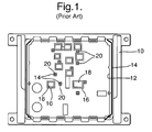
- Fig. 1 depicts an exemplary prior art backplate 10, including a structural adhesive 14 applied to a lip (i.e., a peripheral pedestal) 12 of the backplate 10.
- the structural adhesive 14 is also applied to a plurality of integral support pedestals 20, which support a PCB, when mounted to the backplate 10.
- a thermally conductive adhesive 18 is applied to a plurality of integral heatsinks 16, which are utilized to heatsink IC dies, which are electrically coupled to the PCB (not shown in Fig. 1). It should be appreciated that both the adhesive dispense and adhesive cure steps require material and process time to implement.
- a technique for manufacturing an electronic assembly includes a number of steps. Initially, a mold is provided that has a first mold portion and a second mold portion. The first and second mold portions each include a cavity. The first mold portion includes a plurality of spaced mold pins extending from an inner surface. The cavity of the first and second mold portions provides a mold cavity, when joined.
- a backplate is also provided that includes a plurality of support pedestals and an integrated heatsink extending from a first side of the backplate.
- a substrate is also provided with a first side of an integrated circuit (IC) die mounted to a first side of the substrate.
- IC integrated circuit
- the IC die is electrically connected to one or more of a plurality of electrically conductive traces formed on the first side of the substrate.
- the backplate and the substrate are placed within the cavity of the second mold portion.
- a second side of the backplate is in contact with an inner surface of the second mold portion and a second side of the die is in thermal contact with the heatsink and the support pedestals are in contact with the first side of the substrate.
- the first side of the IC die is opposite the second side of the IC die.
- the first and second mold portions are joined and the mold pins contact a second surface of the substrate.
- the second side of the substrate is opposite the first side of the substrate.
- the mold cavity is filled with an overmold material to provide an overmolded electronic assembly that includes the substrate, the backplate and the overmold material.
- the substrate is a printed circuit board (PCB).
- the substrate includes an electrical connector that provides electrical interconnection to an external device.
- the mold pins may be spring biased and the IC die may be a flip-chip.
- the mold pins and the support pedestals may be arranged opposite one another to reduce mold induced flexure of the substrate.
- the second side of the substrate may include a plurality of resilient pads arranged to contact an end of the mold pins, when the first and second mold portions are joined.
- a solder mask may be utilized to provide the resilient pads.
- a thermal film may also be positioned between the second side of the IC die and the heatsink.
- a technique for manufacturing an electronic assembly includes a number of steps.
- a mold having a first mold portion and a second mold portion is provided.
- the first and second mold portions each include a cavity that provides a mold cavity, when joined.
- a backplate is provided that includes a plurality of support pedestals and an integrated heatsink extending from a first side of the backplate.
- the support pedestals each include an upper compliant portion.
- a substrate includes a first side of an integrated circuit (IC) die mounted to a first side of the substrate.
- the IC die is electrically connected to one or more of a plurality of electrically conductive traces formed on the first side of the substrate.
- the substrate includes a plurality of holes arranged to receive the upper compliant portion of the support pedestals.
- the backplate and substrate are placed within the cavity of the second mold portion, with a second side of the backplate in contact with an inner surface of the second mold portion.
- a second side of the die is in thermal contact with the heatsink and the upper compliant portion of the support pedestals are each received in a different one of the holes in the substrate to interconnect the substrate to the heatsink.
- the first side of the IC die is opposite the second side of the IC die and the first side of the substrate is opposite the second side of the substrate.
- the first and second mold portions are joined and the mold cavity is filled with an overmold material, to provide an overmolded electronic assembly that includes the substrate, the backplate and the overmold material.
- the substrate may be a printed circuit board (PCB) and may include an electrical connector that provides electrical interconnection to an external device.
- the holes in the substrate are plated with an electrically conductive material and the upper compliant portion of the support pedestals are interference fit to electrically ground the backplate to a ground plane of the substrate.
- the IC die may be a flip-chip and a thermal film may be positioned between the second side of the IC die and the heatsink.
- mold pins located in a mold tool secure a substrate, e.g., a populated printed circuit board (PCB), against a backplate during an overmolding process.
- the pins are spring-loaded to provide a specified force to the top side of the PCB.
- Support pedestals of the backplate are positioned on the backside of the substrate, directly opposite the pins, to prevent PCB flexure.
- a solder mask may be located on the top and bottom surfaces of the PCB to act as a cushion for the pins and the support pedestals.
- fine pitch devices such as flip-chips, are implemented as the integrated circuit (IC) die, a series of epoxy support dots may be utilized to ensure solder bump collapse does not create electrical shorts between solder bumps.
- a structural adhesive is not required to attach the PCB to the backplate, as the mold pins and the support pedestals act to secure the PCB within the mold.
- the use of a thermal adhesive between a heatsink pedestal of the backplate and an IC die is not required, as the IC die is closely located to a surface of the heatsink pedestal.
- a mold compound that is utilized to overmold the electronic assembly fills any gap between the flip-chip and the heatsink pedestal to provide an adequate thermal path.
- a thermal pad can be located on a back surface of the die. Additionally, the thermal pad, when implemented, may also take up any tolerance slack in the assembly.
- the thermal pad may be, for example, a graphite-filled thermal film, which typically provides excellent thermal properties for high-power devices with minimal impact on the manufacturing process.
- a PCB may be attached to a backplate with compliant pins.
- the pins may be inserted in portions of the backplate or may be an integral feature of the backplate, e.g., cast into the backplate.
- the pins are inserted through holes in the PCB, which may be plated holes.
- the pins may be interference fit to the plated holes to electrically connect the backplate to a ground plane of the PCB for better electromagnetic interference (EMI) performance.
- EMI electromagnetic interference
- the PCB can be joined to the backplate, prior to the molding process (using a press), or may be secured to the backplate during a clamping cycle, implemented during the molding process.
- the above-described process removes steps from the manufacturing process used to manufacture a prior art electronic assembly. That is, the thermal and structural adhesive dispense steps and the adhesive cure step can be eliminated. This saves both materials and time. Furthermore, the new process effectively decouples IC dies from the backplate, during the molding process. This generally increases the robustness of the manufacturing process, as the process does not rely on a structural adhesive to prevent excessive flexure of the PCB. That is, during the prior art process, if the structural adhesive fails, the stress of the mold compound on the PCB is absorbed by the solder bumps of the flip-chip, which may, as a result of the increased stress, fail.
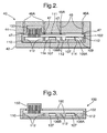
- the mold 40 includes a first mold portion 44 and a second mold portion 42.
- the electronic assembly 100 includes a backplate 110 and a substrate 102. Attached to the substrate 102 are a plurality of integrated circuit (IC) dies 106A and 106B. The dies 106A and 106B are electrically connected to traces formed on a first surface of the substrate 102, via solder bumps 109.
- the backplate 110 includes a plurality of support pedestals 112, which are positioned to support the substrate 102, during the overmolding process.
- the backplate 110 also includes a plurality of integral heatsinks 114, which are utilized to remove heat from the dies 106A and 106B. As is shown in Fig. 2, a thermal film 107 may be positioned between a surface of the heatsinks 114 and the dies 106A and 106B.
- a connector 150 also extends from a second surface of the substrate 102. As is shown, the first mold portion 44 closes on a portion of the connector 150 to prevent leakage of the overmold material to be injected into cavity 111.
- the first mold portion 44 includes a plurality of spaced mold pins 46, which are each individually biased by a spring 46A. An end of the mold pins 46 rests on a resilient support pad 47, which may be, for example, a portion of a solder mask. As is shown, the pins 46 are aligned with the support pedestals 112 of the backplate 110. Thus, during the overmolding process, the pins 46 and the support pedestals 112 (of the backplate 110) support the substrate 102 to prevent excessive flexure of the substrate 102 and damage to the solder bumps 109 that couple the flip-chips 106A and 106B to conductive traces formed on the first surface of the substrate 102.
- Fig. 3 depicts the electronic assembly 100, after the overmolding process has been completed and the assembly 100 has been removed from the mold 40. As is shown, an overmold material 160 underfills a lower portion of the substrate 102 and environmentally seals the substrate 102.
- a mold 40A includes an upper mold portion 44A and a lower mold portion 42, designed according to another embodiment of the present invention. Similar to the mold 40 of Fig. 2, the mold 40A closes on a portion of the connector 150 of the electronic assembly 200. As is shown, a backplate 110A includes a plurality of support pedestals 112A, each with an upper compliant portion that is designed to be received in one of a plurality of holes 103, formed in the substrate 102A.
- Fig. 5 depicts the electronic assembly 200, after the overmolding process has been completed and the assembly 200 has been removed from the mold 40A.
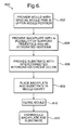
- a process 600 for manufacturing the electronic assembly 100 includes a number of steps.
- a mold 40 is provided.
- the mold 40 may be a two-piece mold that includes the first mold portion 44 and the second mold portion 42.
- the first and second mold portions 44 and 42 each include a cavity and together form a mold cavity 111.
- the first mold 44 includes a plurality of spaced mold pins 46 extending from an inner surface.
- a backplate is provided that includes a plurality of support pedestals 112 and integrated heatsinks 114.
- a substrate 102 is provided that includes a plurality of interconnected integrated circuit (IC) dies 106A and 106B.
- the dies 106A and 106B are mounted to a first side of the substrate 102 and are electrically connected to one or more of a plurality of electrically conductive traces formed on a first side of the substrate 102.
- IC integrated circuit
- step 608 the backplate 110 and the substrate 102 are placed in the second mold portion 42.
- a second side of the backplate 110 is in contact with an inner surface of the second mold portion 42 and a second side of the dies 106A and 106B are in thermal contact with the integrated heatsinks 114.
- the support pedestals 112 are also in contact with the first side of the substrate 102.
- the mold 40 is closed, i.e., the first and second mold portions 44 and 42 are joined.
- the mold pins 46 contact a second surface of the substrate 102 and, according to one embodiment of the present invention, are arranged to be opposite the support pedestals 112.
- the backplate 110 and the substrate 102 are overmolded by filling the mold cavity with an overmold material 160.
- the substrate 102 may be any number of different types of substrates, such as a printed circuit board (PCB).
- the mold pins 46 are biased by spring 46A.
- the second side of the substrate 102 includes a plurality of resilient pads 47 arranged to contact an end of the mold pins 46, when the first and second mold portions 44 and 42 are joined.
- a thermal film 107 may also be positioned between the second side of the IC dies 106A and 106B and the heatsinks 114.
- a process 700 is utilized for manufacturing the electronic assembly 200.
- the mold 40A is provided in step 702.
- the mold 40A includes a first mold portion 44A and a second mold portion 42, which each include a cavity, which, when joined, provide a mold cavity 111.
- a backplate 110A is provided with integrated heatsinks 114 and a plurality of support pedestals 112A, each having an upper compliant portion.
- the substrate 102A is provided with a plurality of integrated circuit (IC) dies 106A and 106B.
- IC integrated circuit
- the substrate 102A also includes a plurality of holes 103, which are designed to receive the upper compliant portion of each of the support pedestals 112A.
- the interconnected backplate 110A and substrate 102A are placed within the mold 40A.
- the backplate 110A and the substrate 102A may be interconnected, after being placed within the mold cavity by the closing of the mold 40A.
- the holes 103 in the substrate 102A are plated with an electrically conductive material and the upper compliant portion of the support pedestals 112A are interference fit in the holes 103 to electrically ground the backplate 110A to a ground plane of the substrate 102A.
- the backplate 110A and the substrate 102A are overmolded to produce the overmolded electronic assembly 200, as is shown in Fig. 5.
Landscapes
- Engineering & Computer Science (AREA)
- Manufacturing & Machinery (AREA)
- Mechanical Engineering (AREA)
- Microelectronics & Electronic Packaging (AREA)
- Encapsulation Of And Coatings For Semiconductor Or Solid State Devices (AREA)
Applications Claiming Priority (1)
| Application Number | Priority Date | Filing Date | Title |
|---|---|---|---|
| US11/167,473 US7268429B2 (en) | 2005-06-27 | 2005-06-27 | Technique for manufacturing an overmolded electronic assembly |
Publications (3)
| Publication Number | Publication Date |
|---|---|
| EP1740027A2 true EP1740027A2 (fr) | 2007-01-03 |
| EP1740027A3 EP1740027A3 (fr) | 2009-06-03 |
| EP1740027B1 EP1740027B1 (fr) | 2019-01-23 |
Family
ID=37106567
Family Applications (1)
| Application Number | Title | Priority Date | Filing Date |
|---|---|---|---|
| EP06076193.9A Active EP1740027B1 (fr) | 2005-06-27 | 2006-06-08 | Procédé de fabrication d'un assemblage électronique surmoulé et assemblage électronique |
Country Status (2)
| Country | Link |
|---|---|
| US (1) | US7268429B2 (fr) |
| EP (1) | EP1740027B1 (fr) |
Cited By (2)
| Publication number | Priority date | Publication date | Assignee | Title |
|---|---|---|---|---|
| WO2013034490A1 (fr) * | 2011-09-05 | 2013-03-14 | Osram Ag | Dispositif d'éclairage et son procédé d'encapsulation |
| EP2687350A4 (fr) * | 2011-03-17 | 2014-09-03 | Iriso Electronics Co Ltd | Produit moulé en résine et procédé de production de ce produit |
Families Citing this family (6)
| Publication number | Priority date | Publication date | Assignee | Title |
|---|---|---|---|---|
| US7473585B2 (en) * | 2005-06-13 | 2009-01-06 | Delphi Technologies, Inc. | Technique for manufacturing an overmolded electronic assembly |
| JP5155890B2 (ja) * | 2008-06-12 | 2013-03-06 | ルネサスエレクトロニクス株式会社 | 半導体装置およびその製造方法 |
| JP2011100718A (ja) * | 2009-10-05 | 2011-05-19 | Yazaki Corp | コネクタ |
| US9623591B2 (en) | 2013-01-15 | 2017-04-18 | Basf Se | Method of encapsulating an electronic component |
| US10403601B2 (en) | 2016-06-17 | 2019-09-03 | Fairchild Semiconductor Corporation | Semiconductor package and related methods |
| JP7198856B2 (ja) * | 2021-03-30 | 2023-01-04 | Nissha株式会社 | 電子部品付き樹脂筐体およびその製造方法 |
Family Cites Families (12)
| Publication number | Priority date | Publication date | Assignee | Title |
|---|---|---|---|---|
| US4679463A (en) | 1984-08-31 | 1987-07-14 | Nissan Motor Co., Ltd. | Limited slip differential |
| JPH03243421A (ja) | 1990-02-19 | 1991-10-30 | Mazda Motor Corp | 車両の動力伝達装置 |
| US5367766A (en) * | 1990-08-01 | 1994-11-29 | Staktek Corporation | Ultra high density integrated circuit packages method |
| US5310388A (en) | 1993-02-10 | 1994-05-10 | Asha Corporation | Vehicle drivetrain hydraulic coupling |
| JP3449681B2 (ja) * | 1997-04-29 | 2003-09-22 | 日本特殊陶業株式会社 | インサート成形体及びその製造方法 |
| US6180045B1 (en) * | 1998-05-20 | 2001-01-30 | Delco Electronics Corporation | Method of forming an overmolded electronic assembly |
| US7062537B2 (en) | 2002-11-25 | 2006-06-13 | Microsoft Corporation | Workflow services architecture |
| US20040148299A1 (en) | 2002-11-25 | 2004-07-29 | Microsoft Corporation | Automated workflow composable action model |
| US7132746B2 (en) * | 2003-08-18 | 2006-11-07 | Delphi Technologies, Inc. | Electronic assembly with solder-bonded heat sink |
| JP2005142215A (ja) * | 2003-11-04 | 2005-06-02 | Japan Aviation Electronics Industry Ltd | 筐体の蓋の変形防止構造 |
| US6905349B1 (en) * | 2004-02-23 | 2005-06-14 | Delphi Technologies, Inc. | Technique for connector to printed circuit board decoupling to eliminate flexure |
| US7473585B2 (en) * | 2005-06-13 | 2009-01-06 | Delphi Technologies, Inc. | Technique for manufacturing an overmolded electronic assembly |
-
2005
- 2005-06-27 US US11/167,473 patent/US7268429B2/en not_active Expired - Lifetime
-
2006
- 2006-06-08 EP EP06076193.9A patent/EP1740027B1/fr active Active
Non-Patent Citations (1)
| Title |
|---|
| None |
Cited By (2)
| Publication number | Priority date | Publication date | Assignee | Title |
|---|---|---|---|---|
| EP2687350A4 (fr) * | 2011-03-17 | 2014-09-03 | Iriso Electronics Co Ltd | Produit moulé en résine et procédé de production de ce produit |
| WO2013034490A1 (fr) * | 2011-09-05 | 2013-03-14 | Osram Ag | Dispositif d'éclairage et son procédé d'encapsulation |
Also Published As
| Publication number | Publication date |
|---|---|
| EP1740027A3 (fr) | 2009-06-03 |
| EP1740027B1 (fr) | 2019-01-23 |
| US7268429B2 (en) | 2007-09-11 |
| US20060292751A1 (en) | 2006-12-28 |
Similar Documents
| Publication | Publication Date | Title |
|---|---|---|
| KR100394809B1 (ko) | 반도체 패키지 및 그 제조 방법 | |
| US7473585B2 (en) | Technique for manufacturing an overmolded electronic assembly | |
| US6133064A (en) | Flip chip ball grid array package with laminated substrate | |
| US6046910A (en) | Microelectronic assembly having slidable contacts and method for manufacturing the assembly | |
| US7196414B2 (en) | Semiconductor package with heat sink | |
| US6849942B2 (en) | Semiconductor package with heat sink attached to substrate | |
| US6774315B1 (en) | Floating interposer | |
| JP5226087B2 (ja) | 基板を介してヒートスプレッダ及び補強材を接地する方法、装置及びフリップチップパッケージ | |
| US20100025810A1 (en) | Method and System for Secure Heat Sink Attachment on Semiconductor Devices with Macroscopic Uneven Surface Features | |
| US7495346B2 (en) | Semiconductor package | |
| JP2004235617A (ja) | 半導体パッケージおよびその製造方法 | |
| US20050040519A1 (en) | Semiconductor package with heat sink | |
| US7268429B2 (en) | Technique for manufacturing an overmolded electronic assembly | |
| JP5160390B2 (ja) | リードピン付配線基板及びその製造方法 | |
| JP5422830B2 (ja) | リードピン付配線基板及びその製造方法 | |
| JP3189270B2 (ja) | 接着方法 | |
| US7432591B1 (en) | Thermal enhanced plastic ball grid array with heat sink attachment option | |
| US20060273467A1 (en) | Flip chip package and method of conducting heat therefrom | |
| CN113380723A (zh) | 一种封装结构 | |
| JPH0812895B2 (ja) | 半導体素子搭載ピングリッドアレイパッケージ基板 | |
| JP2012204717A (ja) | 電子機器、及び電子部品のリワーク方法 | |
| US11164804B2 (en) | Integrated circuit (IC) device package lid attach utilizing nano particle metallic paste | |
| JP5422831B2 (ja) | リードピン付配線基板の製造方法 | |
| JPH0582978B2 (fr) | ||
| JP2007019115A (ja) | フリップチップ型半導体装置およびその製造方法 |
Legal Events
| Date | Code | Title | Description |
|---|---|---|---|
| PUAI | Public reference made under article 153(3) epc to a published international application that has entered the european phase |
Free format text: ORIGINAL CODE: 0009012 |
|
| AK | Designated contracting states |
Kind code of ref document: A2 Designated state(s): AT BE BG CH CY CZ DE DK EE ES FI FR GB GR HU IE IS IT LI LT LU LV MC NL PL PT RO SE SI SK TR |
|
| AX | Request for extension of the european patent |
Extension state: AL BA HR MK YU |
|
| PUAL | Search report despatched |
Free format text: ORIGINAL CODE: 0009013 |
|
| AK | Designated contracting states |
Kind code of ref document: A3 Designated state(s): AT BE BG CH CY CZ DE DK EE ES FI FR GB GR HU IE IS IT LI LT LU LV MC NL PL PT RO SE SI SK TR |
|
| AX | Request for extension of the european patent |
Extension state: AL BA HR MK RS |
|
| 17P | Request for examination filed |
Effective date: 20091203 |
|
| AKX | Designation fees paid |
Designated state(s): AT BE BG CH CY CZ DE DK EE ES FI FR GB GR HU IE IS IT LI LT LU LV MC NL PL PT RO SE SI SK TR |
|
| 17Q | First examination report despatched |
Effective date: 20100128 |
|
| GRAP | Despatch of communication of intention to grant a patent |
Free format text: ORIGINAL CODE: EPIDOSNIGR1 |
|
| STAA | Information on the status of an ep patent application or granted ep patent |
Free format text: STATUS: GRANT OF PATENT IS INTENDED |
|
| INTG | Intention to grant announced |
Effective date: 20180828 |
|
| GRAS | Grant fee paid |
Free format text: ORIGINAL CODE: EPIDOSNIGR3 |
|
| GRAA | (expected) grant |
Free format text: ORIGINAL CODE: 0009210 |
|
| STAA | Information on the status of an ep patent application or granted ep patent |
Free format text: STATUS: THE PATENT HAS BEEN GRANTED |
|
| REG | Reference to a national code |
Ref country code: DE Ref legal event code: R081 Ref document number: 602006057333 Country of ref document: DE Owner name: DELPHI TECHNOLOGIES IP LIMITED, BB Free format text: FORMER OWNER: DELPHI TECHNOLOGIES, INC., TROY, MICH., US |
|
| AK | Designated contracting states |
Kind code of ref document: B1 Designated state(s): AT BE BG CH CY CZ DE DK EE ES FI FR GB GR HU IE IS IT LI LT LU LV MC NL PL PT RO SE SI SK TR |
|
| REG | Reference to a national code |
Ref country code: GB Ref legal event code: FG4D |
|
| REG | Reference to a national code |
Ref country code: CH Ref legal event code: EP |
|
| REG | Reference to a national code |
Ref country code: DE Ref legal event code: R096 Ref document number: 602006057333 Country of ref document: DE |
|
| REG | Reference to a national code |
Ref country code: AT Ref legal event code: REF Ref document number: 1092478 Country of ref document: AT Kind code of ref document: T Effective date: 20190215 |
|
| REG | Reference to a national code |
Ref country code: DE Ref legal event code: R081 Ref document number: 602006057333 Country of ref document: DE Owner name: DELPHI TECHNOLOGIES IP LIMITED, BB Free format text: FORMER OWNER: DELPHI TECHNOLOGIES, INC., TROY, MICH., US |
|
| REG | Reference to a national code |
Ref country code: IE Ref legal event code: FG4D |
|
| REG | Reference to a national code |
Ref country code: GB Ref legal event code: 732E Free format text: REGISTERED BETWEEN 20190214 AND 20190221 |
|
| REG | Reference to a national code |
Ref country code: NL Ref legal event code: MP Effective date: 20190123 |
|
| PG25 | Lapsed in a contracting state [announced via postgrant information from national office to epo] |
Ref country code: NL Free format text: LAPSE BECAUSE OF FAILURE TO SUBMIT A TRANSLATION OF THE DESCRIPTION OR TO PAY THE FEE WITHIN THE PRESCRIBED TIME-LIMIT Effective date: 20190123 |
|
| PG25 | Lapsed in a contracting state [announced via postgrant information from national office to epo] |
Ref country code: FI Free format text: LAPSE BECAUSE OF FAILURE TO SUBMIT A TRANSLATION OF THE DESCRIPTION OR TO PAY THE FEE WITHIN THE PRESCRIBED TIME-LIMIT Effective date: 20190123 Ref country code: SE Free format text: LAPSE BECAUSE OF FAILURE TO SUBMIT A TRANSLATION OF THE DESCRIPTION OR TO PAY THE FEE WITHIN THE PRESCRIBED TIME-LIMIT Effective date: 20190123 Ref country code: ES Free format text: LAPSE BECAUSE OF FAILURE TO SUBMIT A TRANSLATION OF THE DESCRIPTION OR TO PAY THE FEE WITHIN THE PRESCRIBED TIME-LIMIT Effective date: 20190123 Ref country code: PT Free format text: LAPSE BECAUSE OF FAILURE TO SUBMIT A TRANSLATION OF THE DESCRIPTION OR TO PAY THE FEE WITHIN THE PRESCRIBED TIME-LIMIT Effective date: 20190523 Ref country code: LT Free format text: LAPSE BECAUSE OF FAILURE TO SUBMIT A TRANSLATION OF THE DESCRIPTION OR TO PAY THE FEE WITHIN THE PRESCRIBED TIME-LIMIT Effective date: 20190123 Ref country code: PL Free format text: LAPSE BECAUSE OF FAILURE TO SUBMIT A TRANSLATION OF THE DESCRIPTION OR TO PAY THE FEE WITHIN THE PRESCRIBED TIME-LIMIT Effective date: 20190123 |
|
| REG | Reference to a national code |
Ref country code: AT Ref legal event code: MK05 Ref document number: 1092478 Country of ref document: AT Kind code of ref document: T Effective date: 20190123 |
|
| PG25 | Lapsed in a contracting state [announced via postgrant information from national office to epo] |
Ref country code: LV Free format text: LAPSE BECAUSE OF FAILURE TO SUBMIT A TRANSLATION OF THE DESCRIPTION OR TO PAY THE FEE WITHIN THE PRESCRIBED TIME-LIMIT Effective date: 20190123 Ref country code: GR Free format text: LAPSE BECAUSE OF FAILURE TO SUBMIT A TRANSLATION OF THE DESCRIPTION OR TO PAY THE FEE WITHIN THE PRESCRIBED TIME-LIMIT Effective date: 20190424 Ref country code: IS Free format text: LAPSE BECAUSE OF FAILURE TO SUBMIT A TRANSLATION OF THE DESCRIPTION OR TO PAY THE FEE WITHIN THE PRESCRIBED TIME-LIMIT Effective date: 20190523 Ref country code: BG Free format text: LAPSE BECAUSE OF FAILURE TO SUBMIT A TRANSLATION OF THE DESCRIPTION OR TO PAY THE FEE WITHIN THE PRESCRIBED TIME-LIMIT Effective date: 20190423 |
|
| REG | Reference to a national code |
Ref country code: DE Ref legal event code: R097 Ref document number: 602006057333 Country of ref document: DE |
|
| PG25 | Lapsed in a contracting state [announced via postgrant information from national office to epo] |
Ref country code: DK Free format text: LAPSE BECAUSE OF FAILURE TO SUBMIT A TRANSLATION OF THE DESCRIPTION OR TO PAY THE FEE WITHIN THE PRESCRIBED TIME-LIMIT Effective date: 20190123 Ref country code: EE Free format text: LAPSE BECAUSE OF FAILURE TO SUBMIT A TRANSLATION OF THE DESCRIPTION OR TO PAY THE FEE WITHIN THE PRESCRIBED TIME-LIMIT Effective date: 20190123 Ref country code: RO Free format text: LAPSE BECAUSE OF FAILURE TO SUBMIT A TRANSLATION OF THE DESCRIPTION OR TO PAY THE FEE WITHIN THE PRESCRIBED TIME-LIMIT Effective date: 20190123 Ref country code: CZ Free format text: LAPSE BECAUSE OF FAILURE TO SUBMIT A TRANSLATION OF THE DESCRIPTION OR TO PAY THE FEE WITHIN THE PRESCRIBED TIME-LIMIT Effective date: 20190123 Ref country code: IT Free format text: LAPSE BECAUSE OF FAILURE TO SUBMIT A TRANSLATION OF THE DESCRIPTION OR TO PAY THE FEE WITHIN THE PRESCRIBED TIME-LIMIT Effective date: 20190123 Ref country code: SK Free format text: LAPSE BECAUSE OF FAILURE TO SUBMIT A TRANSLATION OF THE DESCRIPTION OR TO PAY THE FEE WITHIN THE PRESCRIBED TIME-LIMIT Effective date: 20190123 |
|
| PLBE | No opposition filed within time limit |
Free format text: ORIGINAL CODE: 0009261 |
|
| STAA | Information on the status of an ep patent application or granted ep patent |
Free format text: STATUS: NO OPPOSITION FILED WITHIN TIME LIMIT |
|
| PG25 | Lapsed in a contracting state [announced via postgrant information from national office to epo] |
Ref country code: AT Free format text: LAPSE BECAUSE OF FAILURE TO SUBMIT A TRANSLATION OF THE DESCRIPTION OR TO PAY THE FEE WITHIN THE PRESCRIBED TIME-LIMIT Effective date: 20190123 |
|
| 26N | No opposition filed |
Effective date: 20191024 |
|
| PG25 | Lapsed in a contracting state [announced via postgrant information from national office to epo] |
Ref country code: MC Free format text: LAPSE BECAUSE OF FAILURE TO SUBMIT A TRANSLATION OF THE DESCRIPTION OR TO PAY THE FEE WITHIN THE PRESCRIBED TIME-LIMIT Effective date: 20190123 |
|
| REG | Reference to a national code |
Ref country code: CH Ref legal event code: PL |
|
| PG25 | Lapsed in a contracting state [announced via postgrant information from national office to epo] |
Ref country code: SI Free format text: LAPSE BECAUSE OF FAILURE TO SUBMIT A TRANSLATION OF THE DESCRIPTION OR TO PAY THE FEE WITHIN THE PRESCRIBED TIME-LIMIT Effective date: 20190123 |
|
| REG | Reference to a national code |
Ref country code: BE Ref legal event code: MM Effective date: 20190630 |
|
| PG25 | Lapsed in a contracting state [announced via postgrant information from national office to epo] |
Ref country code: TR Free format text: LAPSE BECAUSE OF FAILURE TO SUBMIT A TRANSLATION OF THE DESCRIPTION OR TO PAY THE FEE WITHIN THE PRESCRIBED TIME-LIMIT Effective date: 20190123 |
|
| PG25 | Lapsed in a contracting state [announced via postgrant information from national office to epo] |
Ref country code: IE Free format text: LAPSE BECAUSE OF NON-PAYMENT OF DUE FEES Effective date: 20190608 |
|
| PG25 | Lapsed in a contracting state [announced via postgrant information from national office to epo] |
Ref country code: LU Free format text: LAPSE BECAUSE OF NON-PAYMENT OF DUE FEES Effective date: 20190608 Ref country code: CH Free format text: LAPSE BECAUSE OF NON-PAYMENT OF DUE FEES Effective date: 20190630 Ref country code: LI Free format text: LAPSE BECAUSE OF NON-PAYMENT OF DUE FEES Effective date: 20190630 Ref country code: BE Free format text: LAPSE BECAUSE OF NON-PAYMENT OF DUE FEES Effective date: 20190630 |
|
| PG25 | Lapsed in a contracting state [announced via postgrant information from national office to epo] |
Ref country code: CY Free format text: LAPSE BECAUSE OF FAILURE TO SUBMIT A TRANSLATION OF THE DESCRIPTION OR TO PAY THE FEE WITHIN THE PRESCRIBED TIME-LIMIT Effective date: 20190123 |
|
| PG25 | Lapsed in a contracting state [announced via postgrant information from national office to epo] |
Ref country code: HU Free format text: LAPSE BECAUSE OF FAILURE TO SUBMIT A TRANSLATION OF THE DESCRIPTION OR TO PAY THE FEE WITHIN THE PRESCRIBED TIME-LIMIT; INVALID AB INITIO Effective date: 20060608 |
|
| P01 | Opt-out of the competence of the unified patent court (upc) registered |
Effective date: 20230327 |
|
| PGFP | Annual fee paid to national office [announced via postgrant information from national office to epo] |
Ref country code: DE Payment date: 20250509 Year of fee payment: 20 |
|
| PGFP | Annual fee paid to national office [announced via postgrant information from national office to epo] |
Ref country code: GB Payment date: 20250508 Year of fee payment: 20 |
|
| PGFP | Annual fee paid to national office [announced via postgrant information from national office to epo] |
Ref country code: FR Payment date: 20250512 Year of fee payment: 20 |