EP1740073B1 - Taschenmatratze mit getrenntem ende sowie verfahren zu ihrer herstellung - Google Patents
Taschenmatratze mit getrenntem ende sowie verfahren zu ihrer herstellung Download PDFInfo
- Publication number
- EP1740073B1 EP1740073B1 EP05736452A EP05736452A EP1740073B1 EP 1740073 B1 EP1740073 B1 EP 1740073B1 EP 05736452 A EP05736452 A EP 05736452A EP 05736452 A EP05736452 A EP 05736452A EP 1740073 B1 EP1740073 B1 EP 1740073B1
- Authority
- EP
- European Patent Office
- Prior art keywords
- springs
- mattress
- spring
- strings
- slots
- Prior art date
- Legal status (The legal status is an assumption and is not a legal conclusion. Google has not performed a legal analysis and makes no representation as to the accuracy of the status listed.)
- Expired - Lifetime
Links
Images



Classifications
-
- A—HUMAN NECESSITIES
- A47—FURNITURE; DOMESTIC ARTICLES OR APPLIANCES; COFFEE MILLS; SPICE MILLS; SUCTION CLEANERS IN GENERAL
- A47C—CHAIRS; SOFAS; BEDS
- A47C27/00—Spring, stuffed or fluid mattresses or cushions specially adapted for chairs, beds or sofas
- A47C27/04—Spring, stuffed or fluid mattresses or cushions specially adapted for chairs, beds or sofas with spring inlays
- A47C27/06—Spring inlays or spring units therefor
- A47C27/063—Spring inlays or spring units therefor wrapped or otherwise protected
-
- A—HUMAN NECESSITIES
- A47—FURNITURE; DOMESTIC ARTICLES OR APPLIANCES; COFFEE MILLS; SPICE MILLS; SUCTION CLEANERS IN GENERAL
- A47C—CHAIRS; SOFAS; BEDS
- A47C27/00—Spring, stuffed or fluid mattresses or cushions specially adapted for chairs, beds or sofas
- A47C27/04—Spring, stuffed or fluid mattresses or cushions specially adapted for chairs, beds or sofas with spring inlays
- A47C27/06—Spring inlays or spring units therefor
- A47C27/063—Spring inlays or spring units therefor wrapped or otherwise protected
- A47C27/064—Pocketed springs
-
- B—PERFORMING OPERATIONS; TRANSPORTING
- B68—SADDLERY; UPHOLSTERY
- B68G—METHODS, EQUIPMENT, OR MACHINES FOR USE IN UPHOLSTERING; UPHOLSTERY NOT OTHERWISE PROVIDED FOR
- B68G9/00—Placing upholstery springs in pockets; Fitting springs in upholstery
-
- Y—GENERAL TAGGING OF NEW TECHNOLOGICAL DEVELOPMENTS; GENERAL TAGGING OF CROSS-SECTIONAL TECHNOLOGIES SPANNING OVER SEVERAL SECTIONS OF THE IPC; TECHNICAL SUBJECTS COVERED BY FORMER USPC CROSS-REFERENCE ART COLLECTIONS [XRACs] AND DIGESTS
- Y10—TECHNICAL SUBJECTS COVERED BY FORMER USPC
- Y10T—TECHNICAL SUBJECTS COVERED BY FORMER US CLASSIFICATION
- Y10T29/00—Metal working
- Y10T29/48—Upholstered article making
- Y10T29/481—Method
Definitions
- the present invention relates to a spring mattress comprising springs enclosed in casings, referred to as a pocket mattress, as well as a method and a device for manufacturing such a mattress.
- a common technique of making spring mattresses is the so-called pocket technique.
- the springs are enclosed in pockets, i.e. they are individually enclosed by a casing material.
- the springs will be relatively individually resilient so that they can flex individually without affecting the neighboring springs and, thus, the comfort to the user increases since his weight will be distributed more uniformly over the surface that receives the load.
- spring mattresses for many purposes where thinner mattresses are required, such as for bed mattresses, seat cushions and the like.
- spring mattresses have several properties making it desirable to use them also in these contexts, such as excellent comfort, individual flexibility, a long life and easy and inexpensive manufacture.
- a spring mattress comprising a plurality of strings interconnected side by side, each string comprising a plurality of continuous casings and, enclosed therein, coil springs. Moreover, between at least some of the springs in at least one of the strings a slot is arranged which opens towards the upper and lower side of the mattress.
- slots are arranged between substantially all springs in at least one of the strings, and most preferred in substantially all strings.
- the individual resilience over substantially the entire mattress surface is provided with relatively simple means.
- the slots can be arranged so as to open towards only one of the sides of the mattress. This results in different properties on the different mattress sides, which may be advantageous since the user can thus choose mattress properties as desired by turning the mattress to the desired position. Alternatively, however, slots can be arranged on both sides, which means that the mattress can have the same properties, no matter how it is turned.
- the springs between which the slot is arranged can be separated with an intermediate separation distance (SA), which separation distance exceeds about 10% of the diameter of the largest turn of the adjoining springs, and preferably exceeds 15% of the diameter of the largest turn, and most preferred exceeds 20%.
- SA intermediate separation distance
- the slot can be arranged within a separation distance which is provided by a connection, extended in the longitudinal direction of the strings, of the casing material between the springs, the slot being arranged in said extended connection.
- the slot can be arranged in a separation distance which is provided by two separated joint lines arranged between the springs, the slot being arranged between said joint lines.
- the connecting means preferably consists of a mechanical connecting element, such as clamps, or a surface joint, such as gluing or welding.
- a method for manufacturing the mattress discussed above comprises the steps of enclosing springs in casings in continuous strings; interconnecting the strings side by side; and, before or after the preceding steps, arranging a slot between at least some of the springs in at least one of the strings, said slot opening towards the upper and lower side of the mattress.
- This device for manufacturing spring mattresses comprises means for enclosing coil springs in continuous casings to form strings; means for interconnecting strings side by side; and means for arranging slots between springs in such strings, said slots being open towards the upper and lower side of the mattress.
- the device comprises means for biasing the springs enclosed in the strings.
- the means for biasing can advantageously comprise insertion means and, arranged at a distance therefrom, an oppositely extending means, the insertion means and the oppositely extending means being adapted to perform a relative displacement motion towards and away from each other to move casing materials, at the ends of a spring arranged therebetween, towards each other through the spring, and fixing means for arranging connecting members which interconnect the thus moved together casing materials from the two ends of the spring.
- a spring mattress according to the invention comprises a plurality of interconnected coil springs 1 enclosed in casings 2, as shown in Figs 1 and 2 .
- the casing is suitably made of a, preferably weldable, textile material, but also other materials, such as different types of plastic materials, can be used. It is also possible to use non-weldable textile materials, such as cotton cloth.
- Such mattresses referred to as pocket mattresses, are previously known, and therefore the manufacture thereof is not part of the present invention. Normally, strings of interconnected pocket springs in casings are manufactured automatically, after which these strings are cut in suitable lengths and joined side by side to form mattresses.
- slots 3 are arranged between the springs. These slots are open towards one of the mattress sides and extend down between the springs.
- the slots have an extent which is greater than 1/10 of the extent of the casing in the longitudinal direction, and most preferred about 1/3 of this extent.
- the slots are of such an extent that the remaining continuous casing therebetween has an extent which substantially corresponds to the height of the biased springs of the completed mattress, in the case where the mattress is of the type where the end portions are moved towards each other (see below).
- Coil springs of many sizes can be used in connection with the present invention, and basically any size of the springs can be used. However, it is preferred to use springs with a diameter of 2-10 cm, and most preferred about 6 cm.
- the springs comprise preferably at least four turns, and preferably less than 10 turns. Moreover they are advantageously made of spiral wire with a thickness in the range of 0.5 - 3.0 mm, and preferably a wire thickness in the range of 1.25 - 2.50 mm.
- At least two adjoining springs are advantageously arranged with an intermediate separation distance SA, which separation distance exceeds 10% of the diameter of the largest turn of the adjoining springs, and preferably exceeds 15%, and most preferred exceeds 20%. Further the separation distance is preferably greater than 1 cm.
- the casings enclosing the adjoining springs are arranged with an intermediate separation distance SB, which separation distance exceeds 10% of the diameter of the largest turn of the adjoining springs, and preferably exceeds 15%, and most preferred exceeds 20%.
- the separation distance SB is also greater than 1 cm.
- such separation distances are arranged between substantially all springs in the longitudinal direction of the mattress.
- This can be achieved by the strings being provided with two joint lines 4, such as weld joints, to join the casing material on both sides of the springs, which are separated in the longitudinal direction of the strings, as illustrated in Figs 1 and 2 .
- continuous weld lines instead of spot weld joints (not shown).
- other types of joints such as one or more seams.
- mattresses having a length of about 198 cm may comprise less than 30 springs, and most preferred about 25 springs. It is also preferred for mattresses according to the invention to have a spring frequency in the longitudinal direction/directions where the separation distances are inserted, which is less than 15 springs per meter, and preferably less than 13 springs per meter. However, many other sizes of mattresses are of course conceivable.
- the casing portions are, at the spring ends, arranged moved towards each other, through the spring, and connected to each other by connecting means to provide at least a certain degree of bias, as shown in Figs 2 and 3 .
- the casing portions are moved so far towards each other as to make contact with each other, but it is of course possible to interconnect them also otherwise, by means of wire, a long clamp or the like.
- the connecting means may consist of a mechanical connecting element, such as a clamp, a rivet or the like, or a surface joint, such as glue, a welding seam or the like.
- Other fixing elements are, however, also conceivable. The load exerted on the fixing element is normally small since the fixing elements are only loaded if the mattress is unloaded, whereas there is no load at all if the mattress is loaded.
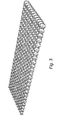
- Fig. 3 shows a mattress made of strings, in which the springs have been separated and biased by moving the end portions of the casings together, as discussed above, and as illustrated in Fig. 2 .
- slots make it possible to maintain the separation between the springs also in the biased state.
- Fig. 4 shows a mattress in which the springs have been separated, but where no bias as described above has occurred, as shown in Fig. 1 .
- the slots ensure an enhanced individual resilience of the enclosed individual springs.
- the mattress according to the invention can be manufactured by the steps of enclosing springs in a casing material, arranging slots between at least some of the springs, optionally biasing at least one of the springs and connecting the springs to each other.
- the step of biasing the springs is, in this case, meant moving casing portions arranged for the ends of the spring towards each other and interconnecting them by connecting elements.
- This bias can occur either immediately after encapsulating the springs in the casing material, i.e. before assembling them to form a mattress, or when the mattress has been assembled.
- the bias preferably occurs when the springs are positioned in strings, and bias of all springs in the mattress layer suitably occurs in this manner.
- the arrangement of the slots may occur before the insertion of the springs into the casing material, after the insertion of the springs but before an optional bias and the joining of the strings, after the bias but before the joining of the strings, or after such joining.
- the arrangement of the slots advantageously occurs after the insertion of the springs but before the additional steps.
- the separation distances will be aligned with each other. This is preferred although it is also possible to arrange the strings so that the springs are offset relative to each other. In the latter case, also the springs all over the mattress can be arranged more closely to each other than in conventional pocket mattresses, even if this is usually not desirable.
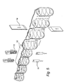
- a device for performing the bias according to the method above comprises an insertion means 11 and, spaced therefrom, an abutment 12, as shown in Figs 5 and 6 .
- springs are arranged so that one spring end faces the insertion means and the other faces the abutment.
- the insertion means is movable towards and away from the abutment to move casing material at a spring end through the spring towards the casing material on the other side.
- fixing means 13 are provided for arranging connecting means which connect the casing materials from the two ends.
- the insertion means is movable past the abutment, and the fixing means is arranged on the opposite side thereof, as shown in the embodiment.
- the insertion means can move the casing material out of the front as well as the rear end through an opening in the abutment, while the abutment prevents the spring from being entrained.
- the fixing means can then fix the casing materials together by a mechanical connecting member, such as a clamp, or by a surface joint, such as gluing or welding.
- a device for arranging the slots according to the method above may also comprise cutting means 14, which can be moved down to the strings between the springs, as shown in Fig. 5 .
- the cutting means can be inserted in the longitudinal direction of the casings, in the transverse direction of the casings, or at any angle therebetween.
- the slot-forming means can be arranged before or after the optional biasing means in a manufacturing device.
- the cutting means can advantageously be arranged in connection with the welding means that are used to form the casings, in which case the slots can be formed simultaneously with the welding or in direct connection thereto.
- the cutting means may consist of blades with a sharpened edge which can be moved down to the slots. Alternatively, cutting edges, which in the forming of the slot are moved towards each other, can be used instead. It is also conceivable to provide slots by heating or like operation.
- a system according to the invention can advantageously comprise a plurality of parallel devices, such as two devices operating in parallel, which is shown in the embodiment.
- the strings with springs are preferably arranged side by side, as indicated in Figs 3 and 4 .
- the rows are connected to each other at 2-3 fixing points vertically distributed just in front of each spring.
- a smaller or greater number of fixing points are conceivable.
- the connection of strings to each other can occur by welding or gluing. Also this connection can, however, alternatively occur by means of clamps, by Velcro tape, or in some other suitable manner.
- the height of the springs can easily be adjusted by varying the positioning of the fixing means.
- the manufacture will in this way be very flexible and controllable.
Landscapes
- Engineering & Computer Science (AREA)
- Mechanical Engineering (AREA)
- Mattresses And Other Support Structures For Chairs And Beds (AREA)
- Springs (AREA)
- Auxiliary Devices For And Details Of Packaging Control (AREA)
- Perforating, Stamping-Out Or Severing By Means Other Than Cutting (AREA)
- Press Drives And Press Lines (AREA)
- Details Of Garments (AREA)
- Wire Processing (AREA)
- Bedding Items (AREA)
Claims (16)
- Federkernmatratze, umfassend eine Vielzahl an Seite an Seite miteinander verbundenen Strängen, wobei jeder Strang eine Vielzahl an durchgehenden Gehäusen (2) aufweist, in denen Schraubenfedern (1) untergebracht sind, wobei Gehäuseabschnitte, die an den Enden der Feder (1) angeordnet sind, durch die Feder (1) zueinander hin bewegt sind und durch Verbindungsmittel miteinander verbunden sind, dadurch gekennzeichnet, dass zumindest zwischen einigen der Federn in zumindest einem der Stränge Schlitze (3) angeordnet sind, die sich zur Oberseite und zur Unterseite der Matratze hin öffnen.
- Federkernmatratze nach Anspruch 1, wobei Schlitz-Paare (3) zwischen im Wesentlichen allen Federn in zumindest einem der Stränge angeordnet ist.
- Federkernmatratze nach Anspruch 1, wobei die Federn, zwischen denen die Schlitze (3) angeordnet sind, durch einen Zwischentrennabstand (SA) getrennt sind, wobei der Trennabstand in etwa 10 % des Durchmessers der größten Windung der benachbarten Federn (1) überschreitet, vorzugsweise 15 % des Durchmessers der größten Windung überschreitet und noch bevorzugter 20 % überschreitet.
- Federkernmatratze nach Anspruch 3, wobei der Trennabstand (SA) durch eine in Längsrichtung der Stränge ausgedehnte Verbindung des Gehäusematerials zwischen den Federn (1) bereitgestellt ist, wobei die Schlitze (3) in dieser ausgedehnten Verbindung angeordnet sind.
- Federkernmatratze nach Anspruch 3, wobei der Trennabstand (SA) durch zwei getrennte Bindenähte bereitgestellt ist, die zwischen den Federn (1) angeordnet sind, wobei die Schlitze (3) zwischen den Bindenähten angeordnet sind.
- Federkernmatratze nach einem der vorangegangenen Ansprüche, wobei das Gehäuse (2) ein vorzugsweise schweißbares Textilmaterial ist.
- Federkernmatratze nach einem der vorangegangenen Ansprüche, wobei die Gehäuseabschnitte so nahe zueinander angeordnet sind, dass sie miteinander in Berührung stehen.
- Federkernmatratze nach Anspruch 7, wobei das Verbindungsmittel ein mechanisches Verbindungselement oder eine Oberflächenverbindung ist.
- Verfahren zum Herstellen einer Federkernmatratze nach Anspruch 1, umfassend die Folgenden Schritte:das Unterbringen von Federn (1) in Gehäusen (2) in durchgehenden Strängen;das Verbinden der Stränge Seite an Seite;das Vorspannen von zumindest einer der Federn durch das Bewegen der für die Enden der Federn angeordneten Gehäuseabschnitte zueinander und das Verbinden dieser mit Verbindungselementen;und, vor oder nach den genannten Schritten,das Bereitstellen von Schlitzen (3) zwischen zumindest einigen der Federn (1) in zumindest einem der Stränge, wobei sich die Schlitze (3) zur Oberseite und zur Unterseite der Matratze hin öffnen.
- Verfahren nach Anspruch 9, wobei zumindest einige der benachbarten Federn (1) innerhalb eines Strangs, zwischen denen Schlitze (3) angeordnet sind, ferner mit einem Zwischentrennabstand (SA) zwischen den Federn angeordnet sind, wobei der Trennabstand in etwa 10 % des Durchmessers der größten Windung der benachbarten Federn überschreitet, vorzugsweise 15 % des Durchmessers der größten Windung überschreitet und noch bevorzugter 20 % überschreitet.
- Verfahren nach Anspruch 9 oder 10, wobei die Gehäuseabschnitte so weit zueinander bewegt werden, dass sie zueinander in Berührung geraten.
- Verfahren nach einem der Ansprüche 9 bis 11, wobei die Schlitze (3) vor dem Vorspannen der Feder angeordnet werden.
- Verfahren nach einem der Ansprüche 9 bis 12, wobei der Trennabstand (SA) der Federn (1) durch Anordnen einer sich in Längsrichtung der Stränge ausgedehnten Verbindung des Gehäusematerials bereitgestellt wird, wobei die Schlitze (3) in dieser ausgedehnten Verbindung angeordnet sind.
- Verfahren nach einem der Ansprüche 9 bis 13, wobei der Trennabstand (SA) durch Anordnen von zwei getrennten Bindenähten (4) bereitgestellt wird, wobei die Schlitze (3) zwischen den Bindenähten angeordnet sind.
- Vorrichtung zum Herstellen einer Federkernmatratze nach Anspruch 1, umfassend:Mittel zum Unterbringen von Spiralfedern (1) in durchgehenden Gehäusen (2), um Stränge auszubilden;Mittel zum Verbinden der Stränge Seite an Seite;Mittel (11, 12, 13) zum Vorspannen der Federn (1), die in den Strängen untergebracht sind;undMittel (14) zum Bereitstellen von Schlitzen zwischen Federn in solchen Strängen, wobei die Schlitze zur Oberseite und zur Unterseite der Matratze hin offen sind.
- Vorrichtung nach Anspruch 15, wobei das Mittel zum Vorspannen ein Einführungsmittel (11) und, in einem Abstand zu diesem angeordnet, ein sich entgegengesetzt erstreckendes Mittel (12) umfasst, wobei das Einführungsmittel und das sich entgegengesetzt erstreckende Mittel dazu geeignet sind, eine relative Verschiebungsbewegung zueinander hin und voneinander weg auszuführen, um Gehäusematerialien an den Enden einer dazwischen angeordneten Feder (1) durch die Feder zueinander zu bewegen, und ferner ein Anbringungsmittel (13) zum Anordnen von Verbindungselementen, die die so zueinander bewegten Gehäusematerialien von den Enden der Feder miteinander verbinden, umfasst.
Priority Applications (1)
| Application Number | Priority Date | Filing Date | Title |
|---|---|---|---|
| PL05736452T PL1740073T3 (pl) | 2004-04-26 | 2005-04-26 | Materac kieszeniowy z rozdzielonym końcem jak również sposób i urządzenie do jego wytwarzania |
Applications Claiming Priority (2)
| Application Number | Priority Date | Filing Date | Title |
|---|---|---|---|
| SE0401061A SE526926C2 (sv) | 2004-04-26 | 2004-04-26 | Ändseparerad pocketmadrass samt metod och anordning för tillverkande av densamma |
| PCT/SE2005/000598 WO2005102115A1 (en) | 2004-04-26 | 2005-04-26 | End separated pocket mattress as well as method and device for manufacturing the same |
Publications (2)
| Publication Number | Publication Date |
|---|---|
| EP1740073A1 EP1740073A1 (de) | 2007-01-10 |
| EP1740073B1 true EP1740073B1 (de) | 2008-10-29 |
Family
ID=32322661
Family Applications (1)
| Application Number | Title | Priority Date | Filing Date |
|---|---|---|---|
| EP05736452A Expired - Lifetime EP1740073B1 (de) | 2004-04-26 | 2005-04-26 | Taschenmatratze mit getrenntem ende sowie verfahren zu ihrer herstellung |
Country Status (11)
| Country | Link |
|---|---|
| US (1) | US7748065B2 (de) |
| EP (1) | EP1740073B1 (de) |
| AT (1) | ATE412355T1 (de) |
| BR (1) | BRPI0510268A (de) |
| DE (1) | DE602005010682D1 (de) |
| DK (1) | DK1740073T3 (de) |
| NO (1) | NO326330B1 (de) |
| PL (1) | PL1740073T3 (de) |
| RU (1) | RU2367326C2 (de) |
| SE (1) | SE526926C2 (de) |
| WO (1) | WO2005102115A1 (de) |
Families Citing this family (37)
| Publication number | Priority date | Publication date | Assignee | Title |
|---|---|---|---|---|
| GB0524468D0 (en) * | 2005-12-01 | 2006-01-11 | Harrison Bedding Ltd | Spring units |
| US9510690B2 (en) | 2006-08-29 | 2016-12-06 | Ascion, Llc | Foam spring mattress configured with variable firmness |
| WO2008048743A2 (en) * | 2006-08-29 | 2008-04-24 | Ascion Llc | A foam spring mattress configured with variable firmness |
| SE530333C2 (sv) * | 2007-01-12 | 2008-05-06 | Stjernfjaedrar Ab | En pocketfjädermadrass samt en metod och anordning för tillverkande av densamma |
| EP2150155B1 (de) * | 2007-05-30 | 2014-07-09 | Petrolati, Cesare | Federmatratze |
| FR2932658A1 (fr) * | 2008-06-20 | 2009-12-25 | Cie Continentale Simmons | Chapelet de ressorts helicoidaux loges respectivement dans des poches individuelles de retenue et suspension pour matelas de literie comprenant une pluralite de tels chapelets. |
| WO2012155131A1 (en) * | 2011-05-12 | 2012-11-15 | Sealy Technology, Llc | Advanced conformance encased coil spring units |
| US20130302554A1 (en) * | 2012-03-14 | 2013-11-14 | Applied Ft Composite Solutions Inc. | Cushioning pad with encapsulated resilient elements |
| US9345334B2 (en) | 2013-06-19 | 2016-05-24 | L&P Property Management Company | Pocketed spring assembly comprising strings of springs having Y-shaped seams separating adjacent pockets |
| US9414692B2 (en) * | 2013-06-19 | 2016-08-16 | L&P Property Management Company | Pocketed spring assembly comprising strings of springs having Y-shaped seams and inserts |
| US9427090B2 (en) * | 2013-06-19 | 2016-08-30 | L&P Property Management Company | Pocketed spring assembly comprising strings of springs having Y-shaped seams |
| US8978183B1 (en) * | 2014-01-08 | 2015-03-17 | L&P Property Management Company | Pocketed spring assembly |
| US11076705B2 (en) | 2014-05-30 | 2021-08-03 | Sealy Technology, Llc | Spring core with integrated cushioning layer |
| US10010190B2 (en) | 2014-06-17 | 2018-07-03 | L&P Property Management Company | Pocketed spring assembly |
| US9370252B2 (en) | 2014-06-17 | 2016-06-21 | L&P Property Management Company | Pocketed spring assembly |
| AU2015396842B2 (en) * | 2015-06-05 | 2018-11-08 | Sealy Technology, Llc | Non-linear springs and mattresses including the same |
| WO2017023640A1 (en) * | 2015-08-03 | 2017-02-09 | Bedgear, Llc | Customizable mattress |
| US11033114B2 (en) | 2015-12-17 | 2021-06-15 | Sealy Technology, Llc | Coil-in-coil spring with variable loading response and mattresses including the same |
| WO2017116406A1 (en) * | 2015-12-29 | 2017-07-06 | Sealy Technology, Llc | Pocket coil spring assemblies having separated seams and support cushions including the same |
| CN108697242B (zh) | 2016-01-21 | 2021-08-20 | 丝涟科技有限责任公司 | 具有非线性负载响应的线圈套线圈弹簧和包括它的垫子 |
| US10598242B2 (en) | 2016-05-20 | 2020-03-24 | Sealy Technology, Llc | Coil springs with non-linear loading responses and mattresses including the same |
| EP3468419B1 (de) * | 2016-06-08 | 2025-07-16 | Bedgear, LLC | Unabhängige aufhängungsfederanordnung |
| US10512340B2 (en) * | 2017-05-31 | 2019-12-24 | L&P Property Management Company | Pocketed spring assembly comprising strings of springs with tabs |
| US10206515B1 (en) * | 2017-09-20 | 2019-02-19 | L&P Property Management Company | Pocketed spring assembly |
| EP3703537B1 (de) | 2017-10-31 | 2024-06-26 | Sealy Technology, LLC | Taschenspiralfederanordnung mit flexiblem schaumstoff |
| PL3706602T3 (pl) * | 2017-11-09 | 2024-05-13 | Ikea Supply Ag | Rdzeń sprężynowy |
| US10973340B2 (en) | 2017-11-15 | 2021-04-13 | Starsprings Ab | Pocket mattress comprising openings in the casing material |
| EP3485766B1 (de) | 2017-11-15 | 2024-05-15 | Starsprings AB | Taschenfeder-matratze mit öffnungen in ihrem gehäusematerial |
| WO2019096793A1 (en) | 2017-11-15 | 2019-05-23 | Starsprings Ab | Pocket mattress comprising openings in the casing material |
| US12369722B2 (en) | 2018-05-23 | 2025-07-29 | L&P Property Management Company | Method of disassembling pocketed spring assembly with dimensionally stabilizing substrate |
| US11013340B2 (en) * | 2018-05-23 | 2021-05-25 | L&P Property Management Company | Pocketed spring assembly having dimensionally stabilizing substrate |
| US11109686B2 (en) * | 2018-06-13 | 2021-09-07 | L&P Property Management Company | Method of making a continuous string of pocketed springs |
| CN115251653B (zh) * | 2021-04-30 | 2023-10-27 | 厦门新技术集成有限公司 | 弹簧包、弹簧垫、家具和制作弹簧包的方法 |
| US12064036B2 (en) | 2021-05-31 | 2024-08-20 | Starsprings Ab | Pocket mattress comprising integrated foam material |
| WO2022253638A1 (en) | 2021-05-31 | 2022-12-08 | Starsprings Ab | Pocket mattress comprising integrated foam material |
| PL4098152T3 (pl) | 2021-05-31 | 2024-08-05 | Starsprings Ab | Materac kieszeniowy zawierający zintegrowany materiał piankowy |
| CN115813147B (zh) * | 2022-02-15 | 2024-03-22 | 厦门新技术集成有限公司 | 弹性垫及具有该弹性垫的家具 |
Family Cites Families (9)
| Publication number | Priority date | Publication date | Assignee | Title |
|---|---|---|---|---|
| CA913815A (en) * | 1969-05-30 | 1972-10-31 | Convexco Limited | Spring upholstery assembly |
| DE9012069U1 (de) | 1990-08-22 | 1990-10-25 | Schlaraffia-Werke Hüser GmbH & Co KG, 4630 Bochum | Taschenfederkern |
| DE4026502C1 (en) * | 1990-08-22 | 1991-06-06 | Schlaraffia-Werke Hueser Gmbh & Co Kg, 4630 Bochum, De | Pocket spring core - has parallel chains of pocketed springs with insert slits extending over half chain height |
| GB9301927D0 (en) * | 1993-02-01 | 1993-03-17 | Spring Quilt Ind Ltd | Pocket spring assemblies |
| DE29718869U1 (de) * | 1997-10-23 | 1998-02-05 | Federnwerke Marienberg Gmbh, 09496 Marienberg | Stabilisierter Taschenfederkern |
| GB9905964D0 (en) * | 1999-03-17 | 1999-05-12 | Springform Technology Limited | Method and apparatus for manufacturing innerspring assemblies |
| SE517533C2 (sv) * | 1999-03-25 | 2002-06-18 | Stjernfjaedrar Ab | Resårmadrass omfattande ett flertal sammankopplade spiralfjädrar, metod för tillverkande av en resårmadrass samt anordning för förspännande av spiralfjädrar |
| SE516172C2 (sv) * | 2000-11-30 | 2001-11-26 | Stjernfjaedrar Ab | Separerad pocketmadrass |
| DE20215963U1 (de) | 2002-10-17 | 2003-05-22 | Schramm Werkstaetten Gmbh | Taschenfederkernmatratze |
-
2004
- 2004-04-26 SE SE0401061A patent/SE526926C2/sv not_active IP Right Cessation
-
2005
- 2005-04-26 BR BRPI0510268-5A patent/BRPI0510268A/pt not_active IP Right Cessation
- 2005-04-26 DE DE602005010682T patent/DE602005010682D1/de not_active Expired - Lifetime
- 2005-04-26 RU RU2006141658/12A patent/RU2367326C2/ru active
- 2005-04-26 DK DK05736452T patent/DK1740073T3/da active
- 2005-04-26 WO PCT/SE2005/000598 patent/WO2005102115A1/en not_active Ceased
- 2005-04-26 EP EP05736452A patent/EP1740073B1/de not_active Expired - Lifetime
- 2005-04-26 US US11/547,800 patent/US7748065B2/en active Active
- 2005-04-26 PL PL05736452T patent/PL1740073T3/pl unknown
- 2005-04-26 AT AT05736452T patent/ATE412355T1/de not_active IP Right Cessation
-
2006
- 2006-11-24 NO NO20065407A patent/NO326330B1/no not_active IP Right Cessation
Also Published As
| Publication number | Publication date |
|---|---|
| US20070289068A1 (en) | 2007-12-20 |
| WO2005102115A1 (en) | 2005-11-03 |
| US7748065B2 (en) | 2010-07-06 |
| ATE412355T1 (de) | 2008-11-15 |
| NO326330B1 (no) | 2008-11-10 |
| SE526926C2 (sv) | 2005-11-22 |
| DE602005010682D1 (de) | 2008-12-11 |
| RU2367326C2 (ru) | 2009-09-20 |
| DK1740073T3 (da) | 2009-02-09 |
| NO20065407L (no) | 2007-01-25 |
| BRPI0510268A (pt) | 2007-10-30 |
| EP1740073A1 (de) | 2007-01-10 |
| RU2006141658A (ru) | 2008-06-10 |
| PL1740073T3 (pl) | 2009-04-30 |
| SE0401061D0 (sv) | 2004-04-26 |
| SE0401061L (sv) | 2005-10-27 |
Similar Documents
| Publication | Publication Date | Title |
|---|---|---|
| US7748065B2 (en) | End separated pocketed mattress as well as method and device for manufacturing the same | |
| CA2577285C (en) | Thin pocket mattress, and method and device for its manufacturing | |
| US6591438B1 (en) | Retracted pocket spring mattress; method for manufacturing of a pocket spring mattress and device for pre-tensioning pocketed coil spings | |
| EP1700820B1 (de) | Taschenfederkernmatratze | |
| EP1047628B1 (de) | Matratze mit doppelfederkern, und verfahren zu ihrer herstellung | |
| EP1691643B1 (de) | Federkernmatratze mit getrennten taschen und durchschnittenem faden und verfahren und vorrichtung zur herstellung einer solchen matratze | |
| US10973340B2 (en) | Pocket mattress comprising openings in the casing material | |
| JP2021527482A5 (ja) | ポケットスプリングマットレス及びスプリングマットレスを製造する方法 | |
| AU2018367067B2 (en) | Pocket mattress comprising openings in the casing material | |
| EP3937731B1 (de) | Komfortschicht mit abstandstaschenfedern | |
| US20200288873A1 (en) | Comfort Layer Having Pocketed Springs of Different Heights | |
| EP3485766B1 (de) | Taschenfeder-matratze mit öffnungen in ihrem gehäusematerial | |
| BRPI0510268B1 (pt) | Spray mattress, method for manufacture of a spray mattress, and device for the manufacture of spring mattresses |
Legal Events
| Date | Code | Title | Description |
|---|---|---|---|
| PUAI | Public reference made under article 153(3) epc to a published international application that has entered the european phase |
Free format text: ORIGINAL CODE: 0009012 |
|
| 17P | Request for examination filed |
Effective date: 20060918 |
|
| AK | Designated contracting states |
Kind code of ref document: A1 Designated state(s): AT BE BG CH CY CZ DE DK EE ES FI FR GB GR HU IE IS IT LI LT LU MC NL PL PT RO SE SI SK TR |
|
| 17Q | First examination report despatched |
Effective date: 20070613 |
|
| DAX | Request for extension of the european patent (deleted) | ||
| GRAP | Despatch of communication of intention to grant a patent |
Free format text: ORIGINAL CODE: EPIDOSNIGR1 |
|
| GRAS | Grant fee paid |
Free format text: ORIGINAL CODE: EPIDOSNIGR3 |
|
| GRAA | (expected) grant |
Free format text: ORIGINAL CODE: 0009210 |
|
| AK | Designated contracting states |
Kind code of ref document: B1 Designated state(s): AT BE BG CH CY CZ DE DK EE ES FI FR GB GR HU IE IS IT LI LT LU MC NL PL PT RO SE SI SK TR |
|
| REG | Reference to a national code |
Ref country code: GB Ref legal event code: FG4D |
|
| REG | Reference to a national code |
Ref country code: CH Ref legal event code: EP |
|
| REG | Reference to a national code |
Ref country code: IE Ref legal event code: FG4D |
|
| REF | Corresponds to: |
Ref document number: 602005010682 Country of ref document: DE Date of ref document: 20081211 Kind code of ref document: P |
|
| REG | Reference to a national code |
Ref country code: DK Ref legal event code: T3 |
|
| REG | Reference to a national code |
Ref country code: GR Ref legal event code: EP Ref document number: 20090400165 Country of ref document: GR |
|
| LTIE | Lt: invalidation of european patent or patent extension |
Effective date: 20081029 |
|
| PG25 | Lapsed in a contracting state [announced via postgrant information from national office to epo] |
Ref country code: BG Free format text: LAPSE BECAUSE OF FAILURE TO SUBMIT A TRANSLATION OF THE DESCRIPTION OR TO PAY THE FEE WITHIN THE PRESCRIBED TIME-LIMIT Effective date: 20090129 Ref country code: AT Free format text: LAPSE BECAUSE OF FAILURE TO SUBMIT A TRANSLATION OF THE DESCRIPTION OR TO PAY THE FEE WITHIN THE PRESCRIBED TIME-LIMIT Effective date: 20081029 Ref country code: ES Free format text: LAPSE BECAUSE OF FAILURE TO SUBMIT A TRANSLATION OF THE DESCRIPTION OR TO PAY THE FEE WITHIN THE PRESCRIBED TIME-LIMIT Effective date: 20090209 Ref country code: LT Free format text: LAPSE BECAUSE OF FAILURE TO SUBMIT A TRANSLATION OF THE DESCRIPTION OR TO PAY THE FEE WITHIN THE PRESCRIBED TIME-LIMIT Effective date: 20081029 |
|
| REG | Reference to a national code |
Ref country code: PL Ref legal event code: T3 |
|
| PG25 | Lapsed in a contracting state [announced via postgrant information from national office to epo] |
Ref country code: SI Free format text: LAPSE BECAUSE OF FAILURE TO SUBMIT A TRANSLATION OF THE DESCRIPTION OR TO PAY THE FEE WITHIN THE PRESCRIBED TIME-LIMIT Effective date: 20081029 Ref country code: PT Free format text: LAPSE BECAUSE OF FAILURE TO SUBMIT A TRANSLATION OF THE DESCRIPTION OR TO PAY THE FEE WITHIN THE PRESCRIBED TIME-LIMIT Effective date: 20090330 Ref country code: IS Free format text: LAPSE BECAUSE OF FAILURE TO SUBMIT A TRANSLATION OF THE DESCRIPTION OR TO PAY THE FEE WITHIN THE PRESCRIBED TIME-LIMIT Effective date: 20090228 |
|
| PG25 | Lapsed in a contracting state [announced via postgrant information from national office to epo] |
Ref country code: RO Free format text: LAPSE BECAUSE OF FAILURE TO SUBMIT A TRANSLATION OF THE DESCRIPTION OR TO PAY THE FEE WITHIN THE PRESCRIBED TIME-LIMIT Effective date: 20081029 Ref country code: EE Free format text: LAPSE BECAUSE OF FAILURE TO SUBMIT A TRANSLATION OF THE DESCRIPTION OR TO PAY THE FEE WITHIN THE PRESCRIBED TIME-LIMIT Effective date: 20081029 |
|
| PG25 | Lapsed in a contracting state [announced via postgrant information from national office to epo] |
Ref country code: SE Free format text: LAPSE BECAUSE OF FAILURE TO SUBMIT A TRANSLATION OF THE DESCRIPTION OR TO PAY THE FEE WITHIN THE PRESCRIBED TIME-LIMIT Effective date: 20090129 Ref country code: CZ Free format text: LAPSE BECAUSE OF FAILURE TO SUBMIT A TRANSLATION OF THE DESCRIPTION OR TO PAY THE FEE WITHIN THE PRESCRIBED TIME-LIMIT Effective date: 20081029 Ref country code: IT Free format text: LAPSE BECAUSE OF FAILURE TO SUBMIT A TRANSLATION OF THE DESCRIPTION OR TO PAY THE FEE WITHIN THE PRESCRIBED TIME-LIMIT Effective date: 20081029 |
|
| PLBE | No opposition filed within time limit |
Free format text: ORIGINAL CODE: 0009261 |
|
| STAA | Information on the status of an ep patent application or granted ep patent |
Free format text: STATUS: NO OPPOSITION FILED WITHIN TIME LIMIT |
|
| PG25 | Lapsed in a contracting state [announced via postgrant information from national office to epo] |
Ref country code: SK Free format text: LAPSE BECAUSE OF FAILURE TO SUBMIT A TRANSLATION OF THE DESCRIPTION OR TO PAY THE FEE WITHIN THE PRESCRIBED TIME-LIMIT Effective date: 20081029 |
|
| 26N | No opposition filed |
Effective date: 20090730 |
|
| REG | Reference to a national code |
Ref country code: CH Ref legal event code: PL |
|
| PG25 | Lapsed in a contracting state [announced via postgrant information from national office to epo] |
Ref country code: LI Free format text: LAPSE BECAUSE OF NON-PAYMENT OF DUE FEES Effective date: 20090430 Ref country code: CH Free format text: LAPSE BECAUSE OF NON-PAYMENT OF DUE FEES Effective date: 20090430 |
|
| REG | Reference to a national code |
Ref country code: IE Ref legal event code: MM4A |
|
| PG25 | Lapsed in a contracting state [announced via postgrant information from national office to epo] |
Ref country code: IE Free format text: LAPSE BECAUSE OF NON-PAYMENT OF DUE FEES Effective date: 20090426 Ref country code: MC Free format text: LAPSE BECAUSE OF NON-PAYMENT OF DUE FEES Effective date: 20090430 |
|
| PG25 | Lapsed in a contracting state [announced via postgrant information from national office to epo] |
Ref country code: LU Free format text: LAPSE BECAUSE OF NON-PAYMENT OF DUE FEES Effective date: 20090426 |
|
| PG25 | Lapsed in a contracting state [announced via postgrant information from national office to epo] |
Ref country code: HU Free format text: LAPSE BECAUSE OF FAILURE TO SUBMIT A TRANSLATION OF THE DESCRIPTION OR TO PAY THE FEE WITHIN THE PRESCRIBED TIME-LIMIT Effective date: 20090430 |
|
| PG25 | Lapsed in a contracting state [announced via postgrant information from national office to epo] |
Ref country code: TR Free format text: LAPSE BECAUSE OF FAILURE TO SUBMIT A TRANSLATION OF THE DESCRIPTION OR TO PAY THE FEE WITHIN THE PRESCRIBED TIME-LIMIT Effective date: 20081029 |
|
| PG25 | Lapsed in a contracting state [announced via postgrant information from national office to epo] |
Ref country code: CY Free format text: LAPSE BECAUSE OF FAILURE TO SUBMIT A TRANSLATION OF THE DESCRIPTION OR TO PAY THE FEE WITHIN THE PRESCRIBED TIME-LIMIT Effective date: 20081029 |
|
| REG | Reference to a national code |
Ref country code: FR Ref legal event code: PLFP Year of fee payment: 12 |
|
| REG | Reference to a national code |
Ref country code: FR Ref legal event code: PLFP Year of fee payment: 13 |
|
| REG | Reference to a national code |
Ref country code: FR Ref legal event code: PLFP Year of fee payment: 14 |
|
| PGFP | Annual fee paid to national office [announced via postgrant information from national office to epo] |
Ref country code: FI Payment date: 20200318 Year of fee payment: 16 Ref country code: PL Payment date: 20200313 Year of fee payment: 16 Ref country code: GR Payment date: 20200318 Year of fee payment: 16 Ref country code: GB Payment date: 20200318 Year of fee payment: 16 Ref country code: DK Payment date: 20200319 Year of fee payment: 16 |
|
| PGFP | Annual fee paid to national office [announced via postgrant information from national office to epo] |
Ref country code: BE Payment date: 20200318 Year of fee payment: 16 |
|
| PGFP | Annual fee paid to national office [announced via postgrant information from national office to epo] |
Ref country code: FR Payment date: 20200318 Year of fee payment: 16 |
|
| PGFP | Annual fee paid to national office [announced via postgrant information from national office to epo] |
Ref country code: NL Payment date: 20200417 Year of fee payment: 16 Ref country code: DE Payment date: 20200318 Year of fee payment: 16 |
|
| REG | Reference to a national code |
Ref country code: DE Ref legal event code: R119 Ref document number: 602005010682 Country of ref document: DE |
|
| REG | Reference to a national code |
Ref country code: FI Ref legal event code: MAE |
|
| REG | Reference to a national code |
Ref country code: DK Ref legal event code: EBP Effective date: 20210430 |
|
| REG | Reference to a national code |
Ref country code: NL Ref legal event code: MM Effective date: 20210501 |
|
| GBPC | Gb: european patent ceased through non-payment of renewal fee |
Effective date: 20210426 |
|
| REG | Reference to a national code |
Ref country code: BE Ref legal event code: MM Effective date: 20210430 |
|
| PG25 | Lapsed in a contracting state [announced via postgrant information from national office to epo] |
Ref country code: GB Free format text: LAPSE BECAUSE OF NON-PAYMENT OF DUE FEES Effective date: 20210426 Ref country code: FR Free format text: LAPSE BECAUSE OF NON-PAYMENT OF DUE FEES Effective date: 20210430 Ref country code: DE Free format text: LAPSE BECAUSE OF NON-PAYMENT OF DUE FEES Effective date: 20211103 Ref country code: FI Free format text: LAPSE BECAUSE OF NON-PAYMENT OF DUE FEES Effective date: 20210426 |
|
| PG25 | Lapsed in a contracting state [announced via postgrant information from national office to epo] |
Ref country code: GR Free format text: LAPSE BECAUSE OF NON-PAYMENT OF DUE FEES Effective date: 20211108 |
|
| PG25 | Lapsed in a contracting state [announced via postgrant information from national office to epo] |
Ref country code: NL Free format text: LAPSE BECAUSE OF NON-PAYMENT OF DUE FEES Effective date: 20210501 |
|
| PG25 | Lapsed in a contracting state [announced via postgrant information from national office to epo] |
Ref country code: DK Free format text: LAPSE BECAUSE OF NON-PAYMENT OF DUE FEES Effective date: 20210430 |
|
| PG25 | Lapsed in a contracting state [announced via postgrant information from national office to epo] |
Ref country code: BE Free format text: LAPSE BECAUSE OF NON-PAYMENT OF DUE FEES Effective date: 20210430 |
|
| PG25 | Lapsed in a contracting state [announced via postgrant information from national office to epo] |
Ref country code: PL Free format text: LAPSE BECAUSE OF NON-PAYMENT OF DUE FEES Effective date: 20210426 |