EP1740400B1 - Fahrassistenzsystem zum ankuppeln eines anhängers unter einsatz einer fahrzeugniveauregulierung - Google Patents
Fahrassistenzsystem zum ankuppeln eines anhängers unter einsatz einer fahrzeugniveauregulierung Download PDFInfo
- Publication number
- EP1740400B1 EP1740400B1 EP05707437A EP05707437A EP1740400B1 EP 1740400 B1 EP1740400 B1 EP 1740400B1 EP 05707437 A EP05707437 A EP 05707437A EP 05707437 A EP05707437 A EP 05707437A EP 1740400 B1 EP1740400 B1 EP 1740400B1
- Authority
- EP
- European Patent Office
- Prior art keywords
- vehicle
- trailer
- assistance system
- coupling
- driver assistance
- Prior art date
- Legal status (The legal status is an assumption and is not a legal conclusion. Google has not performed a legal analysis and makes no representation as to the accuracy of the status listed.)
- Expired - Lifetime
Links
Images

Classifications
-
- B—PERFORMING OPERATIONS; TRANSPORTING
- B60—VEHICLES IN GENERAL
- B60D—VEHICLE CONNECTIONS
- B60D1/00—Traction couplings; Hitches; Draw-gear; Towing devices
- B60D1/24—Traction couplings; Hitches; Draw-gear; Towing devices characterised by arrangements for particular functions
- B60D1/36—Traction couplings; Hitches; Draw-gear; Towing devices characterised by arrangements for particular functions for facilitating connection, e.g. hitch catchers
-
- B—PERFORMING OPERATIONS; TRANSPORTING
- B60—VEHICLES IN GENERAL
- B60D—VEHICLE CONNECTIONS
- B60D1/00—Traction couplings; Hitches; Draw-gear; Towing devices
- B60D1/24—Traction couplings; Hitches; Draw-gear; Towing devices characterised by arrangements for particular functions
- B60D1/42—Traction couplings; Hitches; Draw-gear; Towing devices characterised by arrangements for particular functions for being adjustable
- B60D1/46—Traction couplings; Hitches; Draw-gear; Towing devices characterised by arrangements for particular functions for being adjustable vertically
- B60D1/465—Traction couplings; Hitches; Draw-gear; Towing devices characterised by arrangements for particular functions for being adjustable vertically comprising a lifting mechanism, e.g. for coupling while lifting
-
- B—PERFORMING OPERATIONS; TRANSPORTING
- B60—VEHICLES IN GENERAL
- B60D—VEHICLE CONNECTIONS
- B60D1/00—Traction couplings; Hitches; Draw-gear; Towing devices
- B60D1/58—Auxiliary devices
- B60D1/66—Props
-
- B—PERFORMING OPERATIONS; TRANSPORTING
- B60—VEHICLES IN GENERAL
- B60G—VEHICLE SUSPENSION ARRANGEMENTS
- B60G17/00—Resilient suspensions having means for adjusting the spring or vibration-damper characteristics, for regulating the distance between a supporting surface and a sprung part of vehicle or for locking suspension during use to meet varying vehicular or surface conditions, e.g. due to speed or load
- B60G17/015—Resilient suspensions having means for adjusting the spring or vibration-damper characteristics, for regulating the distance between a supporting surface and a sprung part of vehicle or for locking suspension during use to meet varying vehicular or surface conditions, e.g. due to speed or load the regulating means comprising electric or electronic elements
-
- B—PERFORMING OPERATIONS; TRANSPORTING
- B60—VEHICLES IN GENERAL
- B60G—VEHICLE SUSPENSION ARRANGEMENTS
- B60G2500/00—Indexing codes relating to the regulated action or device
- B60G2500/30—Height or ground clearance
- B60G2500/32—Height or ground clearance of only one vehicle part or side
- B60G2500/324—Height or ground clearance of only one vehicle part or side only rear part
-
- B—PERFORMING OPERATIONS; TRANSPORTING
- B60—VEHICLES IN GENERAL
- B60G—VEHICLE SUSPENSION ARRANGEMENTS
- B60G2800/00—Indexing codes relating to the type of movement or to the condition of the vehicle and to the end result to be achieved by the control action
- B60G2800/20—Stationary vehicle
- B60G2800/203—Stationary vehicle lowering the floor for loading/unloading
-
- B—PERFORMING OPERATIONS; TRANSPORTING
- B60—VEHICLES IN GENERAL
- B60G—VEHICLE SUSPENSION ARRANGEMENTS
- B60G2800/00—Indexing codes relating to the type of movement or to the condition of the vehicle and to the end result to be achieved by the control action
- B60G2800/20—Stationary vehicle
- B60G2800/204—Stationary vehicle adjusting floor height to the loading ramp level
Definitions
- the invention relates to a driving assistance system for coupling a vehicle-mounted to a trailer hitch to a trailer attached to a counterpart.
- the driving assistance system described therein has a display of an image of a rear view camera on a display device, the particular automatically generated guides can be superimposed when a given instruction input is received. Through these guides, the driver can see on the display device how he must steer the vehicle to place the vehicle-mounted trailer hitch in the vicinity of the trailer-mounted counterpart.
- the merging of the two coupling parts can be done by means of a threaded post, which can lift the trailer-side part of the coupling and lowered onto the vehicle-side part of the coupling with the help of a crank under the use of human muscle power.
- a driver assistance system having the features of the preamble of claim 1 is of the generic type GB 7 387 582 A known.
- the object of the invention is to provide a driver assistance system that allows a simple fast and auto matized coupling of a trailer to a vehicle.
- the driver assistance system for coupling a trailer coupling attached to a vehicle to a counterpart attached to a trailer is characterized in that a Control unit is provided in the vehicle, which controls at least one actuator of a vehicle level control in the presence of a predetermined first condition such that at least the rear part of the vehicle is lowered and / or in the presence of a predetermined second condition at least one actuator of a vehicle level control such controls that at least the rear part of the vehicle is raised.
- Such a driver assistance system offers the advantage of coupling a trailer to a motor vehicle without much effort.
- Trailers may be, for example, campers, or trailers, which are used to transport heavy or bulky goods or animal transport.
- the control unit, which controls the actuators of the vehicle level control can be combined for cost and / or space reasons with an already existing in the vehicle control unit or as a pure software function in one or more existing control units (possibly also subsequently) implemented. Since a vehicle level control is already present in many vehicles, there are no additional costs for these actuators for the driver assistance system according to the invention.
- the actuators of the vehicle level control or the vehicle level control itself are configured, either the rear part of the vehicle alone or the entire vehicle is lowered or raised in the presence of the predetermined first or second condition.
- the reduction or increase takes place by an appropriate amount.
- the vehicle level control system can also be understood to mean an adjustable air suspension system or a stabilization system for cornering.
- the predetermined first condition is when the detected by a sensor unit distance between the vehicle-mounted towing hitch and the trailer attached counterpart falls below a predetermined distance value and / or if the vehicle-mounted trailer hitch with the trailer-mounted counterpart without maneuvering is moved together ,
- the sensor unit is used for automatic detection of at least the counterpart attached to the trailer for determining its relative position and / or the distance to the vehicle-side coupling.
- Said sensor unit may be based on an optical, ultrasound-based, capacitive, inductive, sensor, a combination of these sensors, or based on a RADAR or LIDAR device.
- the determination of the relative position and / or the distance between the two parts of the trailer coupling is advantageous as the condition for the lowering of the at least rear part of the vehicle so as to ensure with a high probability that the driver intends a coupling of the trailer.
- the sensor unit also includes the corresponding data evaluation. These can be realized spatially separated from the sensors in a separate or other existing control device.
- these may, for example, carry a special marking.
- the marker may have a specific color, texture or wave reflectance properties.
- a single dedicated vehicle level control operating element can be actuated to activate the Ankupplungsvorgangs.
- an already existing pushbutton or switch can be assigned a double function. Thus, the vehicle is lowered with absolute certainty only if the driver so wishes.
- the sensor unit is designed as a development of an environment-recognizing or sometimeswiederweden assistance system.
- This may advantageously be a reversing camera system and / or a Park Distance Control System (PDC).
- PDC Park Distance Control System
- the image evaluation in an existing rearview camera system for example, be designed so that it recognizes in a first step by means of an automatic object detection unit mounted on the vehicle trailer hitch and attached to the trailer counterpart and their relative position or only the distance between them automatically calculated from the image data.
- the automatic object recognition unit can be configured such that even when changing the trailer hitch mounted on the vehicle this is clearly recognized.
- An environment-recognizing assistance system may, for example, also be understood as meaning an optical or RADAR- or LIDAR-based guidance assistance system or a pre-crash sensor unit.
- the sensor unit is connected to a display device which is mounted in a location that can be seen from a driver's seat and the. Position of the vehicle-mounted trailer hitch relative to the position of the trailer-mounted counterpart as a geometrically transformed video image or in symbolic form shows.
- the driver has the opportunity to place by means of the display device in a simple manner, the vehicle-mounted trailer hitch directly to the pendant attached to the counterpart. If both coupling parts are sufficiently sufficiently positioned relative to one another, it can not according to the invention automatically inform the driver that he should at least allow the rear part of the vehicle to be lowered automatically by actuating a control element.
- the operating element can also be designed as part of a multi-functional operating element or a voice or gesture recognition.
- the display device can be designed as a head-up display.
- the representation may be either a symbolic representation of the two coupling parts and / or a representation of a geometrically transformed camera image. A geometric transformation of the image can be understood as a virtual change of the camera perspective and / or electronic equalization and / or an enlargement or deformation of specific image areas.
- the representation can also be made such that it gives the driver a three-dimensional impression of the scene.
- the vehicle level control control as a soft-key.
- the driver is informed that he should now initiate or confirm at least the lowering of the rear part of his vehicle by the operation of said control element to place the vehicle-mounted towing hitch under the trailer-mounted counterpart.
- the development of the invention by the display of Rangier- symbols is also very beneficial.
- Symbols may represent at least one recommended steering direction for bringing together the two coupling parts and / or a numerical indication of the distance between the two coupling parts. For example, if detected by the sensor unit, the vehicle-mounted towing hitch and attached to the trailer counterpart, the relative position of the two components (trailer hitch and counterpart) can be displayed on the display device, which should be easier for the driver who mounted on the vehicle To place the trailer hitch as comfortably and precisely as possible at or below the trailer-side counterpart. Switching symbols can also be lines that are displayed, for example, as the optimum calculated driving line and symbolically represented recommended steering operations.
- the control unit controls a steering system and / or a drive unit and / or a brake unit of the vehicle in such a way depending on the relative position of the vehicle-mounted trailer coupling to the trailer-mounted counterpart such that the vehicle on the vehicle attached trailer hitch under the trailer placed counterpart is placed.
- it may be useful to have the automatic execution of the described automatic actions for example, be confirmed in several steps, for example by actuating a control element.
- the predetermined second condition exists if the trailer coupling present on the vehicle detected by the sensor unit is placed under a counterpart present on the trailer. This eliminates the need for manual lowering of the trailer-side coupling on the vehicle-side clutch, as is currently common.
- the vehicle level control lift control may be the same control as it is to lower.
- the inventive movement sequence of the vehicle relative to the trailer for coupling the trailer was in this description schematically in several steps (start, lower chassis level, drive under the trailer-side clutch, lift chassis level) divided.
- the coupling of a trailer can also take place in a single continuous movement, which is composed of superposition of at least two of the movements to be carried out according to the invention, without departing from the content of the patent claims.
- the rear part of the vehicle is raised such that the counterpart attached to the trailer in such a way is raised, that a the trailer in the parked state supporting device is automatically folded.
- the supporting device may for example be equipped with a spring which is in a tensioned position when supporting the trailer. If the weight of the trailer is displaced so that no weight is stored on the supporting device, the spring contracts and the supporting device automatically flips upwards.
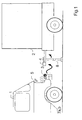
- the Fig. 1 shows a vehicle 1 to which a rear view camera 5 as an optical sensor, an ultrasonic sensor 6 and a trailer hitch 3 is mounted.
- a counterpart 4 is attached to the trailer hitch 3 and is supported by a trailer supporting device 8 without manual crank means.
- Fig. 2 shows an embodiment of the driver assistance system according to the invention as a block diagram. Same components in Fig. 1 and Fig. 2 are provided with the same reference numerals.
- control unit 9 By the control unit 9, the actuators 7a to 7d of the vehicle level control 17 are activated.
- vehicle level control in turn has its own control unit 10, in which also the Control unit of the driver assistance system according to the invention may be included.
- the driver assistance system shown schematically as an example includes at least one reversing camera 5 as an optical sensor and / or one or more ultrasonic sensors sensor 6.
- the reversing camera 5 and the ultrasonic sensor 6 are connected to a control unit 9, which is formed here, for example, as part of the rearview camera system.
- the sensor unit can only be based on the rear camera system.
- the sensor unit 16 has a control unit 9 which in this example is realized as part of the control unit of the reversing camera system.
- the control unit can also be merely a software function that is implemented in a control unit already present in the vehicle.
- the system further comprises a display unit 11 with a vehicle level control operating element 12, which may also be in the form of two operating elements 12a and 12b for lowering or raising the at least rear part of the vehicle 1 or as part of a multifunctional operating element or voice or gesture recognition can.
- a vehicle level control operating element 12 which may also be in the form of two operating elements 12a and 12b for lowering or raising the at least rear part of the vehicle 1 or as part of a multifunctional operating element or voice or gesture recognition can.
- the driver assistance system according to the invention for coupling a trailer coupling 3 attached to a vehicle 1 to a counterpart 4 attached to a trailer 2 is characterized in that a control unit 9 is provided in the vehicle 1 and at least one actuator of the present invention if a predetermined first condition B1a or B1b is present Actuators 7a to 7d of the vehicle level control 17 controls such that at least the rear part of the vehicle 1 is lowered and / or in the presence of a predetermined second condition B2a or B2b at least one actuator of the actuators 7a to 7d of the vehicle level control 17 controls such that at least the rear part of the vehicle 1 is raised.
- the predetermined first condition exists when the distance detected by the sensor unit 16 between the trailer coupling 3 attached to the vehicle 1 and the counterpart 4 attached to the trailer 2 falls below at least a predetermined distance value and / or when the trailer coupling 3 attached to the vehicle 1 engages with the vehicle body 1
- Trailer 2 mounted counterpart 4 is moved together without maneuvering (B1a) or not according to the invention when the designated vehicle level control operating element 12a or 12b (shown in this image as a soft key in the image from the rear camera) is actuated (B1b).
- the sensor unit 16 is connected to the display device 11, which is mounted in a location that can be seen from a driver's seat and shows the position of the attached to the vehicle 1 trailer hitch 3 relative to the position of the attached to the trailer 2 counterpart 4.
- the vehicle level control operating element 12a or 12b is mounted within the reachability range of the driver, upon actuation of which the control unit controls at least one of the actuators 7a-7d of the vehicle level control 17 such that at least the rear portion of the vehicle 1 lowers. 12b is configured as a soft key on the display device 11.
- the display shown on the display device 11 is supplemented by a clear symbolic representation of the automatically generated maneuvering suggestions, eg. In the form of arrows.
- the driver assistance system can in a particular embodiment possibility by means of a not shown here
- Operating element can be set such that the control unit 9 in the presence of the predetermined first condition B1a or B1b depending on the detected by the sensor unit 16 relative position of the vehicle 1 mounted to the trailer coupling 3 to the attached to the trailer 2 counterpart 4, a steering system 13 and / or a drive unit 14 and / or a brake unit 15 of the vehicle 1 such that the attached to the vehicle 1 trailer hitch 3 is placed fully automatically or semi-automatically under the mounted on the trailer 2 counterpart 4.
- the control unit 9 controls at least one of the actuators 7a - 7b of the vehicle level control 17 such that at least the rear part of the vehicle 1 is raised.
- the predetermined second condition exists when the trailer coupling 3 present on the vehicle 1 detected by means of the sensor unit 16 is placed under the counterpart 4 present on the trailer 2 (B2a) or not according to the invention when a vehicle level control operating element (B2b) is actuated.
Landscapes
- Engineering & Computer Science (AREA)
- Mechanical Engineering (AREA)
- Transportation (AREA)
- Control Of Driving Devices And Active Controlling Of Vehicle (AREA)
- Traffic Control Systems (AREA)
- Regulating Braking Force (AREA)
- Vehicle Body Suspensions (AREA)
- Auxiliary Drives, Propulsion Controls, And Safety Devices (AREA)
- Output Control And Ontrol Of Special Type Engine (AREA)
Description
- Die Erfindung bezieht sich auf ein Fahrassistenzsystem zum Ankuppeln einer an einem Fahrzeug angebrachten Anhängerkupplung an ein an einem Anhänger angebrachten Gegenstück.
- Das Ankuppeln eines Anhängers an ein Fahrzeug ist in der Regel umständlich und oftmals problembehaftet. Bei herkömmlichen Fahrzeugen ist keine direkte Sicht auf die am Fahrzeug angebrachte Anhängerkupplung möglich, wodurch ein gezieltes Platzieren der am Fahrzeug angebrachten Anhängerkupplung in der Nähe des am Anhänger angebrachten Gegenstücks nur schwer möglich ist, wenn außer dem Fahrer keine weiteren Hilfspersonen anwesend sind.
- Aus der
EP 1 249 365 B1 ist ein Fahrunterstützungssystem bekannt, welches Abhilfe für das oben genannte Problem bringen soll. Das dort beschriebene Fahrunterstützungssystem weist eine Anzeige eines Bildes von einer Rückfahrkamera auf einer Anzeigeeinrichtung auf, dem bestimmte automatisch erzeugte Hilfslinien überlagert werden können, wenn eine vorgegebene Anweisungseingabe empfangen wird. Durch diese Hilfslinien kann der Fahrer auf der Anzeigeeinrichtung erkennen, wie er das Fahrzeug lenken muss,um die am Fahrzeug angebrachte Anhängerkupplung in der Nähe des am Anhänger angebrachten Gegenstücks zu platzieren. - Das eigentliche Zusammenführen der beiden Teile der Anhängerkupplung stellt weiterhin einen manuellen Vorgang dar.
- Nach dem gegenwärtigen Stand der Technik kann das Zusammenführen der beiden Kupplungsteile mit Hilfe einer Gewindestütze geschehen, die mit Hilfe einer Kurbel unter dem Einsatz der menschlichen Muskelkraft den anhängerseitigen Teil der Kupplung anheben und auf die fahrzeugseitigen Teil der Kupplung heruntergelassen kann.
- Dies ist mit einem Kraftaufwand, Komforteinschränkung und Zeitverlust verbunden. Eine denkbare Alternative stellt eine motorisierte Gewindeeinrichtung dar, die allerdings zu einer deutlichen Kostenerhöhung der Einrichtung führt.
- Ein Fahrassistenzsystem, welches die Merkmale des Oberbegriffs des Anspruchs 1 aufweist, ist aus der gattungsbildenden
GB 7 387 582 A - Diese Aufgabe wird erfindungsgemäß durch ein Fahrerassistenzsystem nach Patentanspruch 1 gelöst. Vorteilhafte Weiterbildungen sind die Gegenstände der abhängigen Ansprüche.
- Das erfindungsgemäße Fahrerassistenzsystem zum Ankuppeln einer an einem Fahrzeug angebrachten Anhängerkupplung an ein an einem Anhänger angebrachten Gegenstück zeichnet sich dadurch aus, dass eine Steuereinheit im Fahrzeug vorgesehen ist, die bei Vorliegen einer vorgegebenen ersten Bedingung zumindest einen Aktuator einer Fahrzeugniveauregulierung derart ansteuert, dass zumindest der hintere Teil des Fahrzeugs abgesenkt wird und/oder bei Vorliegen einer vorgegebenen zweiten Bedingung zumindest einen Aktuator einer Fahrzeugniveauregulierung derart ansteuert, dass zumindest der hintere Teil des Fahrzeugs angehoben wird.
- Ein derartiges Fahrerassistenzsystem bietet den Vorteil, ohne große Anstrengung einen Anhänger an ein Kraftfahrzeug anzukuppeln. Anhänger können bspw. Wohnmobile sein, oder Anhänger, die zum Transport schwerer oder sperriger Güter oder zum Tiertransport dienen. Das Steuergerät, das die Aktuatoren der Fahrzeugniveauregulierung ansteuert, kann aus Kosten- und/oder Platzgründen mit einem bereits im Fahrzeug vorhanden Steuergerät kombiniert sein oder als eine reine Softwarefunktion in einem oder mehreren bereits bestehenden Steuergeräten (eventuell auch nachträglich) implementiert werden. Da eine Fahrzeugniveauregulierung bereits in vielen Fahrzeugen vorhanden ist, entstehen keine zusätzlichen Kosten für diese Aktuatoren für das erfindungsgemäße Fahrerassistenzsystem. Je nachdem, wie die Aktuatoren der Fahrzeugniveauregulierung bzw. die Fahrzeugniveauregulierung selbst ausgestaltet sind, wird bei Vorliegen der vorgegebenen ersten bzw. zweiten Bedingung entweder der hintere Teil des Fahrzeugs allein oder das gesamte Fahrzeug abgesenkt bzw. angehoben.
- Die Absenkung bzw. Anhebung erfolgt um eine angemessene Höhe. Durch die Absenkung kann die fahrzeugseitige Kupplung unter dem anhängerseitigen Gegenstück platziert werden, ohne dass das letztere zuvor angehoben werden muss. Unter dem Fahrzeugniveauregulierungssystem kann auch ein regelbares Luftfederungssystem oder ein Stabilisierungssystem für die Kurvenfahrt verstanden werden.
- Die vorgegebene erste Bedingung liegt dann vor, wenn der mittels einer Sensorseinheit erfasste Abstand zwischen der am Fahrzeug angebrachten Anhängerkupplung und dem am Anhänger angebrachten Gegenstück einen vorgegebenen Abstandswert unterschreitet und/oder wenn die am Fahrzeug angebrachten Anhängerkupplung mit dem am Anhänger angebrachten Gegenstück ohne Rangieren zusammenfahrbar ist.
- Ohne weiteres Rangieren bedeutet hierbei, dass das Fahrzeug bereits so positioniert ist, dass der Lenkwinkel, aber nicht mehr die Fahrrichtung (vorwärts oder rückwärts) geändert wird.
- Vorteilhafterweise dient die Sensoreinheit zu einer automatischen Erkennung von zumindest dem am Anhänger angebrachten Gegenstück zur Bestimmung ihrer relativen Position und/oder des Abstandes zu der fahrzeugsseitigen Kupplung. Die besagte Sensorseinheit kann auf einem optischen, ultraschalbasierten, kapazitiven, induktiven, Sensor basieren, eine Kombination dieser Sensoren enthalten oder auf einer RADAR- oder LIDAR-Einrichtung basieren.
- Unter den optischen Sensoren kann hier auch ein auf dem Prinzip TOL (=Time of Flight) basierendes Sensorsystem verstanden werden. Die Bestimmung der relativen Position und/oder des Abstandes zwischen den beiden Teilen der Anhängerkupplung ist als die Bedingung zu der Absenkung des zumindest hinteren Fahrzeugteils ist insoweit vorteilhaft, um mit einer großen Wahrscheinlichkeit sicherzustellen, dass der Fahrzeugführer eine Ankupplung des Anhängers beabsichtigt. Die Sensoreinheit umfasst auch die entsprechende Datenauswertung. Diese kann räumlich getrennt von den Sensoren in einem separaten oder anderem bereits bestehenden Steuergerät realisiert werden.
- Zu einer erleichterten automatischen Erkennung.der Kupplungsteile können diese bspw. eine spezielle Markierung tragen. Die Markierung kann eine spezielle Farbe, Textur oder Wellenreflektionseigehschaften besitzen.
- Anstelle von der automatischen Sensierung/Objekterkennung kann zur Aktivierung des Ankupplungsvorgangs aber auch nicht erfindungsgemäss ein einziges dafür vorgesehenes Fahrzeugniveauregulierungs-Bedienelement betätigt werden. Anstelle des einzigen dafür vorgesehenes Fahrzeugniveauregulierungs-Bedienelements kann auch ein ohnehin vorhandener Taster oder Schalter mit einer Doppelfunktion belegt werden. Somit wird das Fahrzeug mit absoluter Sicherheit nur abgesenkt, wenn der Fahrer dies wünscht.
- Vorteilhafterweise ist die Sensorseinheit als Weiterbildung eines umfelderkennenden oder bildwiedergebenden Assistenzsystems ausgebildet. Dies kann vorteilhafterweise ein Rückfahrkamerasystem und/oder ein Park Distance Control System (PDC) sein. Hierfür kann bspw. die Bildauswertung in einem bereits bestehenden Rückfahrkamerasystem bspw. derart ausgebildet sein, dass sie in einem ersten Schritt mittels einer automatischen Objekterkennungseinheit die am Fahrzeug angebrachte Anhängerkupplung und das am Anhänger angebrachte Gegenstück erkennt und ihre relative Position bzw. nur den Abstand zwischen ihnen automatisch aus den Bilddaten berechnet. Die automatische Objekterkennungseinheit kann derart ausgestaltet sein, dass auch bei einem Wechsel der am Fahrzeug angebrachten Anhängerkupplung diese eindeutig erkannt wird. Unter einem umfelderkennenden Assistenzsystems kann bspw. auch ein optisch oder RADAR- oder LIDAR-basiertes Spurführungsassistenzsystem oder eine Pre-Crash-Sensoreinheit verstanden werden.
- Vorteilhafterweise ist die Sensorseinheit mit einer Anzeigeeinrichtung verbunden, die an einem Ort angebracht ist, der von einem Fahrersitz aus gesehen werden kann und die. Position der am Fahrzeug angebrachten Anhängerkupplung relativ zur Position des am Anhänger angebrachten Gegenstücks als ein geometrisch transformiertes Videobild oder in symbolischer Form aufzeigt.
- Dadurch hat der Fahrer die Möglichkeit, mittels der Anzeigeeinrichtung auf einfache Weise die am Fahrzeug angebrachte Anhängerkupplung direkt bei dem am Anhänger angebrachtem Gegenstück zu platzieren. Sind beide Kupplungsteile ausreichend günstig genug zueinander positioniert, kann nicht erfindungsgemäss es dem Fahrer automatisch mitgeteilt werden, dass er zumindest den hinteren Teil des Fahrzeugs durch Betätigung eines Bedienelements automatisch absenken lassen sollte. Das Bedienelement kann auch als Teil eines mulifunktionalen Bedienelements oder ein Sprach- oder Gestikerkennung ausgebildet sein kann. Die Anzeigeeinrichtung kann als ein Head-Up-Display ausgebildet sein. Die Darstellung kann entweder eine symbolische Darstellung der beiden Kupplungsteile und/oder eine Darstellung eines geometrisch transformierten Kamerabildes sein. Unter einer geometrischen Transformation des Bildes kann eine virtuelle Veränderung der Kameraperspektive und/oder elektronische Entzerrung und/oder eine Vergrößerung oder Verformung bestimmter Bildbereiche verstanden werden. Die Darstellung kann auch derart erfolgen, dass sie dem Fahrer einen dreidimensionalen Eindruck der Szene vermittelt.
- Vorteilhafterweise sind aus Komfort-, Design- oder Kostengründen auf der Anzeigeeinrichtung Rangier-Hilfslinien und/oder Hilfssymbole und/oder ein Soft-Key als Fahrzeugniveauregulierungs-Bedienelement dargestellt.
- Unterschreitet der Abstand zwischen der am Fahrzeug angebrachten Anhängerkupplung und dem am Anhänger angebrachte Gegenstück einen vorgegebenen Grenzwert und/oder weist die relative Position der beiden Kupplungsteile auf einen unmittelbar bevorstehenden Kupplungsvorgang hin, erscheint nicht erfindungsgemäss auf der Anzeigeeinrichtung das Fahrzeugniveauregulierungs-Bedienelement als Soft-Key. Dem Fahrer wird dadurch mitgeteilt, dass er nun durch die Betätigung des besagten Bedienelements zumindest die Absenkung des hinteren Teil seines Fahrzeugs einleiten oder bestätigen sollte, um die am Fahrzeug angebrachte Anhängerkupplung unter das am Anhänger angebrachte Gegenstück zu platzieren. Die erfindungsgemäße Weiterbildung durch die Anzeige von Rangier- Symbolen ist ebenfalls sehr vorteilhaft.
- Symbole können zumindest eine empfohlene Lenkrichtung zum zusammenführen der beiden Kupplungsteile und/oder eine numerische Anzeige des Abstandes zwischen den beiden Kupplungsteilen darstellen. Wird bspw. durch die Sensorseinheit die am Fahrzeug angebrachte Anhängerkupplung und das am Anhänger angebrachte Gegenstück automatisch erkannt, kann die relative Position der beiden Komponenten (Anhängerkupplung und Gegenstück) auf der Anzeigeeinrichtung schematisch dargestellt werden, wodurch dem Fahrer erleichtert werden soll, die am Fahrzeug angebrachte Anhängerkupplung möglichst komfortabel und präzise bei oder unter dem anhängerseitigen Gegenstück zu platzieren. Rangier-Symbole können auch Linien sein, die bspw. als optimale berechnete Fahrlinie und symbolisch dargestellte empfohlene Lenkvorgänge eingeblendet werden.
- Vorteilhafterweise steuert die Steuereinheit bei Vorliegen der vorgegebenen ersten Bedingung in Abhängigkeit von der durch die Sensorseinheit erfassten relativen Position der am Fahrzeug angebrachten Anhängerkupplung zu dem am Anhänger angebrachten Gegenstück ein Lenksystem und/oder eine Antriebseinheit und/oder eine Bremseinheit des Fahrzeugs derart an, dass die am Fahrzeug angebrachte Anhängerkupplung unter dem am Anhänger angebrachten Gegenstück platziert wird. Hierbei kann es aus Sicherheits- und/oder gesetzlichen Gründen sinnvoll sein, die automatische Ausführung der beschriebenen automatischen Aktionen bspw. in mehreren Schritten, bspw durch Betätigung eines Bedienelements, bestätigen zu lassen. Somit besteht die Möglichkeit die am Fahrzeug angebrachte Anhängerkupplung teil- oder vollautomatisch direkt unter dem am Anhänger angebrachten Gegenstück zu platzieren.
- Die vorgegebene zweite Bedingung liegt dann vor, wenn die mittels der Sensorseinheit erfasste am Fahrzeug vorhandene Anhängerkupplung unter einem am Anhänger vorhandenen Gegenstück platziert ist. Hiermit kann die Notwendigkeit eines manuellen Absenkens der anhängerseitigen Kupplung auf die fahrzeugseitigen Kupplung, wie dies derzeit verbreitet ist, entfallen. Das Fahrzeugniveauregulierungs-Bedienelement zum Anheben kann das gleiche Bedienelement wie zu absenken sein.
- Der erfindungsgemäße Bewegungsablauf des Fahrzeuges gegenüber dem Anhänger zum Ankuppeln des Anhängers wurde in dieser Beschreibung schematisch in mehrere Schritte (anfahren, Fahrgestellniveau absenken, unter die anhängerseitige Kupplung fahren, Fahrgestellniveau anheben) unterteilt. Bei dem erfindungsgemäßen Fahrerassistenzsystem kann das Ankuppeln eines Anhängers auch in einer einzigen kontinuierlichen Bewegung, die sich aus Überlagerung von mindestens zwei der erfindungsgemäß durchzuführenden Bewegungen zusammensetzt, geschehen, ohne den Inhalt der Patentansprüche zu verlassen.
- Vorteilhafterweise wird nach der Ausführung von einem oder mehrerer oben beschriebener Verfahrensschritte der hintere Teil des Fahrzeugs derart angehoben, dass das am Anhänger angebrachte Gegenstück derart mitangehoben wird, dass eine die den Anhänger im abgestellten Zustand stützende Einrichtung automatisch eingeklappt wird.
- Die stützende Einrichtung kann beispielsweise mit einer Feder ausgestattet sein, die in einer gespannten Lage ist, wenn sie den Anhänger abstützt. Wird das Gewicht des Anhängers verlagert, dass auf der stützenden Einrichtung kein Gewicht mehr lagert, zieht sich die Feder zusammen und die stützende Einrichtung wird automatisch nach oben geklappt.
- In der Zeichnung ist ein Ausführungsbeispiel der Erfindung dargestellt. Es zeigt
- Fig. 1
- ein Fahrzeug mit einer am Fahrzeug angebrachten Anhängerkupplung und einen Anhänger mit einem am Anhänger angebrachten Gegenstück und
- Fig. 2
- ein Ausführungsbeispiel des erfindungsgemäßen Fahrerassistenzsystems.
- Die
Fig. 1 zeigt ein Fahrzeug 1, an dem eine Rückfahrkamera 5 als optischer Sensor, ein Ultraschallsensor 6 und eine Anhängerkupplung 3 angebracht ist. An einem Anhänger 2 ist ein Gegenstück 4 zur Anhängerkupplung 3 angebracht und wird durch eine den Anhänger stützende Einrichtung 8 ohne manuelle Kurbeleinrichtung gestützt. -
Fig. 2 zeigt ein Ausführungsbeispiel des erfindungsgemäßen Fahrerassistenzsystems als ein Blockdiagramm. Gleiche Bauteile inFig. 1 undFig. 2 sind mit gleichen Bezugszeichen versehen. - Durch die Steuereinheit 9 werden die Aktuatoren 7a bis 7d der Fahrzeugniveauregulierung 17 angesteuert. Die Fahrzeugniveauregulierung besitzt wiederum ein eigenes Steuergerät 10, in dem ebenfalls die Steuereinheit des erfindungsgemäßen Fahrerassistenzsystems enthalten sein kann.
- Das als Beispiel schematisch dargestellte Fahrerassistenzsystem umfasst zumindest eine Rückfahrkamera 5 als optischen Sensor und/oder einen oder mehrere Ultraschalsensoren Sensor 6. Die Rückfahrkamera 5 und der Ultraschallsensor 6 sind mit einer Steuereinheit 9 verbunden, die hier beispielsweise als ein Teil vom Rückfahrkamerasystem ausgebildet ist. Aus Kostengründen kann die Sensoreinheit nur auf dem Heckkamerasystem basieren. Die Sensoreinheit 16 verfügt über eine Steuereinheit 9 die in diesem Beispiel als Teil des Steuergeräts des Rückfahrkamerasystems realisiert wird. Die Steuereinheit kann aber auch lediglich eine Softwarefunktion sein, die in einem bereits im Fahrzeug vorhandenen Steuergerät implementiert ist.
- Weiter umfasst das System eine Anzeigeeinheit 11 mit einem Fahrzeugniveauregulierungs-Bedienelement 12, das auch in Form von zwei Bedienelemente 12a und 12b zum absenken bzw. anheben des zumindest hinteren Teil des Fahrzeuges 1 oder als Teil eines mulifunktionalen Bedienelements oder ein Sprach- oder Gestikerkennung ausgebildet sein kann. Durch das Steuergerät 10 der Fahrzeugniveauregulierung 17 werden die Aktuatoren 7a bis 7d einer Fahrzeugniveauregulierung 17 angesteuert.
- Das erfindungemäße Fahrerassistenzsystem zum Ankuppeln einer an einem Fahrzeug 1 angebrachten Anhängerkupplung 3 an ein an einem Anhänger 2 angebrachten Gegenstück 4 zeichnet sich dadurch aus, dass eine Steuereinheit 9 im Fahrzeug 1 vorgesehen ist und bei Vorliegen einer vorgegebenen ersten Bedingung B1a oder B1b zumindest ein Aktuator der Aktuatoren 7a bis 7d der Fahrzeugniveauregulierung 17 derart ansteuert, dass zumindest der hintere Teil des Fahrzeugs 1 abgesenkt wird und/oder bei Vorliegen einer vorgegebenen zweiten Bedingung B2a oder B2b zumindest ein Aktuator der Aktuatoren 7a bis 7d der Fahrzeugniveauregulierung 17 derart ansteuert, dass zumindest der hintere Teil des Fahrzeugs 1 angehoben wird.
- Die vorgegebene erste Bedingung liegt vor, wenn der mittels der Sensorseinheit 16 erfasste Abstand zwischen der am Fahrzeug 1 angebrachten Anhängerkupplung 3 und dem am Anhänger 2 angebrachten Gegenstück 4 zumindest einen vorgegebenen Abstandswert unterschreitet und/oder wenn die am Fahrzeug 1 angebrachten Anhängerkupplung 3 mit dem am Anhänger 2 angebrachten Gegenstück 4 ohne Rangieren zusammenfahrbar ist (B1a) oder nicht erfindungsgemäss wenn das dafür vorgesehene Fahrzeugniveauregulierungs-Bedienelement 12a bzw. 12b (in diesem Bild als ein Soft-Key im Bild von der Heckkamera eingeblendet) betätig wird (B1b).
- Wie bereits erwähnt ist die Sensorseinheit 16 mit der Anzeigeeinrichtung 11 verbunden, die an einem Ort angebracht ist, der von einem Fahrersitz aus gesehen werden kann und die Position der am Fahrzeug 1 angebrachten Anhängerkupplung 3 relativ zur Position des am Anhänger 2 angebrachten Gegenstücks 4 aufzeigt. Das Fahrzeugniveauregulierungs-Bedienelement 12a bzw. 12b ist im Erreichbarkeitsbereich des Fahrers angebracht, bei dessen Betätigung die Steuereinheit zumindest einen der Aktuatoren 7a - 7d der Fahrzeugniveauregulierung 17 derart ansteuert, dass sich zumindest der hintere Teil des Fahrzeugs 1 absenkt Das Fahrzeugniveauregulierungs-Bedienelement 12a bzw. 12b ist als Soft-Key auf der Anzeigeeinrichtung 11 ausgestaltet. Die auf der Anzeigeeinrichtung 11 dargestellte Anzeige wird durch eine übersichtliche symbolische Darstellung der automatisch erzeugten Rangiervorschlägen, bspw. in Form von Pfeilen, ergänzt.
- Das Fahrerassistenzsystem kann in einer besonderen Ausgestaltungsmöglichkeit mittels eines hier nicht dargestellten Bedienelements derart eingestellt werden, dass die Steuereinheit 9 bei Vorliegen der vorgegebenen ersten Bedingung B1a bzw. B1b in Abhängigkeit von der durch die Sensorseinheit 16 erfasste relative Position der am Fahrzeug 1 angebrachten Anhängerkupplung 3 zu dem am Anhänger 2 angebrachten Gegenstück 4 ein Lenksystem 13 und/oder eine Antriebseinheit 14 und/oder eine Bremseinheit 15 des Fahrzeugs 1 derart ansteuert, dass die am Fahrzeug 1 angebrachte Anhängerkupplung 3 unter dem am Anhänger 2 angebrachten Gegenstück 4 vollautomatisch oder teilautomatisch platziert wird.
- Bei einem abgesenkten Fahrzeug 1 und bei Vorliegen der vorgegebenen zweiten Bedingung B2a bzw. B2b steuert die Steuereinheit 9 zumindest einen der Aktuatoren 7a - 7b der Fahrzeugniveauregulierung 17 derart an, dass zumindest der hintere Teil des Fahrzeugs 1 angehoben wird. Die vorgegebene zweite Bedingung liegt vor, wenn die mittels der Sensorseinheit 16 erfasste am Fahrzeug 1 vorhandene Anhängerkupplung 3 unter dem am Anhänger 2 vorhandenen Gegenstück 4 platziert ist (B2a) oder nicht erfindungsgemäss wenn ein Fahrzeugniveauregulierungs-Bedienelement (B2b) betätig wird.
- Es können eine Vielzahl weiterer Details durchaus abweichend von obiger Beschreibung gestaltet sein, ohne den Inhalt der Patentansprüche zu verlassen.
Claims (8)
- Fahrerassistenzsystem zum Ankuppeln einer an einem Fahrzeug (1) angebrachten Anhängerkupplung (3) an ein an einem Anhänger (2) angebrachten Gegenstück (4), wobei eine Steuereinheit (9) im Fahrzeug (1) vorgesehen ist, die bei Vorliegen einer vorgegebenen ersten Bedingung (B1a;B1b) zumindest einen Aktuator (7a;7b;7c;7d) einer Fahrzeugniveauregulierung (17) derart ansteuert, dass zumindest der hintere Teil des Fahrzeugs (1) abgesenkt wird und/oder bei Vorliegen einer vorgegebenen zweiten Bedingung (B2a;B2b) zumindest einen Aktuator (7a;7b;7c;7d) einer Fahrzeugniveauregulierung (17) derart ansteuert, dass zumindest der hintere Teil des Fahrzeugs (1) angehoben wird, dadurch gekennzeichnet, dass die vorgegebene erste Bedingung vorliegt, wenn der mittels einer Sensorseinheit (16) erfasste Abstand zwischen der am Fahrzeug (1) angebrachten Anhängerkupplung (3) und dem am Anhänger (2) angebrachten Gegenstück (4) einen vorgegebenen Abstandswert unterschreitet und/oder wenn die am Fahrzeug (1) angebrachten Anhängerkupplung (3) mit dem am Anhänger (2) angebrachten Gegenstück (4) ohne Rangieren zusammenfahrbar ist (B1a), und /oder die zweite Bedingung vorliegt, wenn mittels der Sensoreinheit (16) erkannt wird, dass die am Fahrzeug (1) angebrachten Anhängerkupplung (3) unter dem am Anhänger (2) angebrachten Gegenstück (4) platziert ist (B2a).
- Fahrerassistenzsystem nach Patentanspruch 1 mit einer Sensoreinheit, dadurch gekennzeichnet, dass die Sensorseinheit (16) zumindest einen optischen und/oder ultraschallbasierten und/oder kapazitiven und/oder induktiven Sensor (5;6) und/oder eine RADAR- und/oder eine LIDAR-basierte Einrichtung zum Erfassen des Abstands zwischen der am Fahrzeug (1) angebrachten Anhängerkupplung (3) und dem am Anhänger (2) angebrachten Gegenstück (4) umfasst.
- Fahrerassistenzsystem nach einem der vorangegangenen Patentansprüche, dadurch gekennzeichnet, dass die Sensorseinheit (16) als Weiterbildung eines umfelderkennenden oder bildwiedergebenden Assistenzsystems ausgebildet ist.
- Fahrerassistenzsystem nach Patentanspruch 3, dadurch gekennzeichnet, dass das umfeldumfassende Assistenzsystem ein Rückfahrkamerasystem und/oder ein Park Distance Control System ist.
- Fahrerassistenzsystem nach einem der vorangegangenen Patentansprüche, dadurch gekennzeichnet, dass die Sensorseinheit (16) mit einer Anzeigeeinrichtung (11) verbunden ist, die an einem Ort angebracht ist, der von einem Fahrersitz aus gesehen werden kann und die Position der am Fahrzeug (1) angebrachten Anhängerkupplung (3) relativ zur Position des am Anhänger (2) angebrachten Gegenstücks (4) als ein geometrisch transformiertes Videobild oder in symbolischer Form aufzeigt.
- Fahrerassistenzsystem nach Patentanspruch 5, dadurch gekennzeichnet, dass auf der Anzeigeeinrichtung Rangier-Symbole und/oder ein Soft-Key als Fahrzeugniveauregulierungs-Bedienelement (12a) dargestellt sind.
- Fahrerassistenzsystem nach einem der vorangegangenen Patentansprüche mit einer Sensorseinheit (16), dadurch gekennzeichnet, dass die Steuereinheit (9) bei Vorliegen der vorgegebenen ersten Bedingung (B1a;B1 b) in Abhängigkeit von der durch die Sensorseinheit (16) erfassten relativen Position der am Fahrzeug (1) angebrachten Anhängerkupplung (3) zu dem am Anhänger (2) angebrachten Gegenstück (4) ein Lenksystem (13) und/oder eine Antriebseinheit (14) und/oder eine Bremseinheit (15) des Fahrzeugs (1) derart ansteuert, dass die am Fahrzeug (1) angebrachte Anhängerkupplung (3) unter dem am Anhänger (2) angebrachten Gegenstück (4) platziert wird.
- Fahrerassistenzsystem nach einem der vorangegangenen Patentansprüche, dadurch gekennzeichnet, dass der hintere Teil des Fahrzeugs (1) derart angehoben wird, dass das am Anhänger (2) angebrachte Gegenstück (4) derart mitangehoben wird, dass eine die den Anhänger (2) im abgestellten Zustand stützende Einrichtung (8) automatisch eingeklappt wird.
Applications Claiming Priority (2)
| Application Number | Priority Date | Filing Date | Title |
|---|---|---|---|
| DE102004008928A DE102004008928A1 (de) | 2004-02-24 | 2004-02-24 | Verfahren zum Ankuppeln eines Anhängers unter Einsatz einer Fahrzeugniveauregulierung |
| PCT/EP2005/001570 WO2005080100A1 (de) | 2004-02-24 | 2005-02-16 | Verfahren zum eines anhängers unter einsatz einer fahrzeugniveauregulierung |
Publications (2)
| Publication Number | Publication Date |
|---|---|
| EP1740400A1 EP1740400A1 (de) | 2007-01-10 |
| EP1740400B1 true EP1740400B1 (de) | 2008-04-16 |
Family
ID=34833008
Family Applications (1)
| Application Number | Title | Priority Date | Filing Date |
|---|---|---|---|
| EP05707437A Expired - Lifetime EP1740400B1 (de) | 2004-02-24 | 2005-02-16 | Fahrassistenzsystem zum ankuppeln eines anhängers unter einsatz einer fahrzeugniveauregulierung |
Country Status (7)
| Country | Link |
|---|---|
| US (1) | US7429051B2 (de) |
| EP (1) | EP1740400B1 (de) |
| JP (1) | JP4610604B2 (de) |
| CN (1) | CN100513213C (de) |
| AT (1) | ATE392322T1 (de) |
| DE (2) | DE102004008928A1 (de) |
| WO (1) | WO2005080100A1 (de) |
Cited By (12)
| Publication number | Priority date | Publication date | Assignee | Title |
|---|---|---|---|---|
| DE102011000668C5 (de) * | 2011-02-11 | 2016-03-24 | Haldex Brake Products Gmbh | Verfahren zur Fahrerunterstützung bei einem Andock-Vorgang eines Nutzfahrzeugs an einer Rampe |
| DE102016011323A1 (de) | 2016-09-21 | 2018-03-22 | Wabco Gmbh | Verfahren zur Erkennung und/oder Steuerung eines Ankupplungsvorgangs zwischen einem Zugfahrzeug und einem Fahrzeuganhänger |
| DE102016011324A1 (de) | 2016-09-21 | 2018-03-22 | Wabco Gmbh | Verfahren zur Steuerung eines Zugfahrzeugs bei dessen Heranfahren und Ankuppeln an ein Anhängerfahrzeug |
| US10670479B2 (en) | 2018-02-27 | 2020-06-02 | Methode Electronics, Inc. | Towing systems and methods using magnetic field sensing |
| US10696109B2 (en) | 2017-03-22 | 2020-06-30 | Methode Electronics Malta Ltd. | Magnetolastic based sensor assembly |
| US11084342B2 (en) | 2018-02-27 | 2021-08-10 | Methode Electronics, Inc. | Towing systems and methods using magnetic field sensing |
| US11135882B2 (en) | 2018-02-27 | 2021-10-05 | Methode Electronics, Inc. | Towing systems and methods using magnetic field sensing |
| US11221262B2 (en) | 2018-02-27 | 2022-01-11 | Methode Electronics, Inc. | Towing systems and methods using magnetic field sensing |
| DE102020121497A1 (de) | 2020-08-17 | 2022-02-17 | Zf Cv Systems Global Gmbh | Verfahren zum Ankoppeln eines Aufliegers an ein Zugfahrzeug, Ankoppel-Steuereinrichtung und Fahrzeug |
| DE102021106979A1 (de) | 2021-03-22 | 2022-09-22 | Zf Cv Systems Global Gmbh | Verfahren zum automatisierten Ankoppeln eines Aufliegers an ein Zugfahrzeug, Ankoppel-Anordnung und Fahrzeug |
| US11491832B2 (en) | 2018-02-27 | 2022-11-08 | Methode Electronics, Inc. | Towing systems and methods using magnetic field sensing |
| WO2024056496A1 (de) | 2022-09-16 | 2024-03-21 | Zf Cv Systems Global Gmbh | Verfahren zum steuern eines fahrzeug-gespanns und fahrzeug-gespann |
Families Citing this family (93)
| Publication number | Priority date | Publication date | Assignee | Title |
|---|---|---|---|---|
| DE102005052238A1 (de) * | 2005-11-02 | 2007-05-03 | GM Global Technology Operations, Inc., Detroit | Fahrassistenzsystem mit einem Sensorsystem |
| DE102006001059A1 (de) * | 2006-01-07 | 2007-07-12 | GM Global Technology Operations, Inc., Detroit | Anhängerkupplung |
| GB2447672B (en) | 2007-03-21 | 2011-12-14 | Ford Global Tech Llc | Vehicle manoeuvring aids |
| DE102007044535B4 (de) | 2007-09-18 | 2022-07-14 | Bayerische Motoren Werke Aktiengesellschaft | Verfahren zur Fahrerinformation in einem Kraftfahrzeug |
| US8308182B2 (en) * | 2008-07-16 | 2012-11-13 | Ford Global Technologies, Llc | Trailer connection assist system |
| DE102008034606A1 (de) | 2008-07-25 | 2010-01-28 | Bayerische Motoren Werke Aktiengesellschaft | Verfahren zur Darstellung der Umgebung eines Fahrzeugs auf einer mobilen Einheit |
| DE102008064951B3 (de) | 2008-07-25 | 2022-11-10 | Bayerische Motoren Werke Aktiengesellschaft | Verfahren zur Information eines Insassen eines Fahrzeuges |
| DE102008034594B4 (de) | 2008-07-25 | 2021-06-24 | Bayerische Motoren Werke Aktiengesellschaft | Verfahren sowie Informationssystem zur Information eines Insassen eines Fahrzeuges |
| DE102008046215A1 (de) | 2008-09-08 | 2009-09-17 | Daimler Ag | Verfahren zur Ankoppelung eines Fahrzeugs an eine Ladestation |
| US8191915B2 (en) | 2008-10-17 | 2012-06-05 | GM Global Technology Operations LLC | Vehicle docking assistance system |
| DE102009030452A1 (de) | 2009-06-25 | 2010-03-25 | Daimler Ag | Verfahren zum Betrieb eines Fahrerassistenzsystems eines Fahrzeuges |
| DE102009045284A1 (de) * | 2009-10-02 | 2011-04-07 | Robert Bosch Gmbh | Verfahren zur Unterstützung eines Fahrers eines Kraftfahrzeugs |
| US9969428B2 (en) | 2011-04-19 | 2018-05-15 | Ford Global Technologies, Llc | Trailer backup assist system with waypoint selection |
| US9555832B2 (en) | 2011-04-19 | 2017-01-31 | Ford Global Technologies, Llc | Display system utilizing vehicle and trailer dynamics |
| US9374562B2 (en) * | 2011-04-19 | 2016-06-21 | Ford Global Technologies, Llc | System and method for calculating a horizontal camera to target distance |
| US9854209B2 (en) | 2011-04-19 | 2017-12-26 | Ford Global Technologies, Llc | Display system utilizing vehicle and trailer dynamics |
| US9506774B2 (en) | 2011-04-19 | 2016-11-29 | Ford Global Technologies, Llc | Method of inputting a path for a vehicle and trailer |
| US9723274B2 (en) | 2011-04-19 | 2017-08-01 | Ford Global Technologies, Llc | System and method for adjusting an image capture setting |
| US9926008B2 (en) | 2011-04-19 | 2018-03-27 | Ford Global Technologies, Llc | Trailer backup assist system with waypoint selection |
| US9683848B2 (en) | 2011-04-19 | 2017-06-20 | Ford Global Technologies, Llc | System for determining hitch angle |
| US9290204B2 (en) | 2011-04-19 | 2016-03-22 | Ford Global Technologies, Llc | Hitch angle monitoring system and method |
| US9500497B2 (en) | 2011-04-19 | 2016-11-22 | Ford Global Technologies, Llc | System and method of inputting an intended backing path |
| DE102011112274A1 (de) | 2011-09-05 | 2013-03-07 | Brose Fahrzeugteile Gmbh & Co. Kg, Hallstadt | Steuersystem |
| WO2013034561A1 (en) * | 2011-09-06 | 2013-03-14 | Land Rover | Suspension control device |
| DE102011121775B3 (de) | 2011-12-21 | 2013-01-31 | Brose Fahrzeugteile Gmbh & Co. Kg, Hallstadt | Steuersystem |
| DE102012003992A1 (de) * | 2012-02-28 | 2013-08-29 | Wabco Gmbh | Zielführungssystem für Kraftfahrzeuge |
| US8976246B1 (en) * | 2012-04-03 | 2015-03-10 | Michael E. Rappuhn | Gooseneck or fifth wheel trailer hitch alignment and safety system |
| DE102012207648A1 (de) * | 2012-05-08 | 2013-11-14 | Bayerische Motoren Werke Aktiengesellschaft | Fahrerassistenzsystem zum teilautomatischen Kuppeln eines zweispurigen Kraftfahrzeugs mit einem Anhänger |
| CN102661749A (zh) * | 2012-05-11 | 2012-09-12 | 苏州大方特种车股份有限公司 | 动力平板运输车精确对接控制系统 |
| DE102012013065A1 (de) | 2012-07-02 | 2014-01-02 | Brose Fahrzeugteile Gmbh & Co. Kg, Hallstadt | Verfahren zur Ansteuerung einer Verschlusselementanordnung eines Kraftfahrzeugs |
| DE102012014676A1 (de) * | 2012-07-25 | 2014-01-30 | Brose Fahrzeugteile Gmbh & Co. Kg, Hallstadt | Verfahren zur Ansteuerung einer Verschlusselementanordnung insbesondere eines Kraftfahrzeugs |
| US9288446B2 (en) | 2012-09-10 | 2016-03-15 | Nissan North America, Inc. | Vehicle video system |
| US9511799B2 (en) | 2013-02-04 | 2016-12-06 | Ford Global Technologies, Llc | Object avoidance for a trailer backup assist system |
| US9592851B2 (en) | 2013-02-04 | 2017-03-14 | Ford Global Technologies, Llc | Control modes for a trailer backup assist system |
| NO20130966A1 (no) * | 2013-07-11 | 2015-01-12 | Smart Patents As | System og fremgangsmåte for automatisk å koble en tilhenger til et kjøretøy |
| US10556473B2 (en) | 2013-07-11 | 2020-02-11 | Smart Patents As | System and method for connecting or disconnecting a trailer to a vehicle |
| JP2017502866A (ja) * | 2013-11-18 | 2017-01-26 | ローベルト ボツシユ ゲゼルシヤフト ミツト ベシユレンクテル ハフツングRobert Bosch Gmbh | 連結のためのオーバヘッドビュー |
| DE102013019925B4 (de) * | 2013-11-22 | 2021-01-28 | Audi Ag | Kamerasystem und Verfahren zum Betreiben eines solchen Systems sowie Fahrzeug |
| DE102013114881A1 (de) | 2013-12-25 | 2015-06-25 | Brose Fahrzeugteile Gmbh & Co. Kommanditgesellschaft, Hallstadt | Steuersystem für eine motorische Verschlusselementanordnung eines Kraftfahrzeugs |
| DE102013114883A1 (de) | 2013-12-25 | 2015-06-25 | Brose Fahrzeugteile Gmbh & Co. Kommanditgesellschaft, Hallstadt | Steuersystem für eine motorische Verschlusselementanordnung eines Kraftfahrzeugs |
| CN103754076A (zh) * | 2014-01-04 | 2014-04-30 | 张少靖 | 一种汽车牵引车与挂车辅助对接装置 |
| DE102014110498A1 (de) * | 2014-07-25 | 2016-01-28 | Dr. Ing. H.C. F. Porsche Aktiengesellschaft | Verfahren zum Unterstützen eines Ankuppelvorgangs eines Kraftfahrzeugs an einen Anhänger |
| US9522677B2 (en) | 2014-12-05 | 2016-12-20 | Ford Global Technologies, Llc | Mitigation of input device failure and mode management |
| US9533683B2 (en) | 2014-12-05 | 2017-01-03 | Ford Global Technologies, Llc | Sensor failure mitigation system and mode management |
| US9607242B2 (en) | 2015-01-16 | 2017-03-28 | Ford Global Technologies, Llc | Target monitoring system with lens cleaning device |
| US10046613B2 (en) * | 2015-02-17 | 2018-08-14 | Daniel Robert Shepard | Dual purpose hitch sensor |
| DE102015213404A1 (de) * | 2015-07-16 | 2017-01-19 | Continental Teves Ag & Co. Ohg | Verfahren und Vorrichtung zum Ankuppeln eines Kraftfahrzeugs an einen Anhänger |
| DE102015112589A1 (de) | 2015-07-31 | 2017-02-02 | Brose Fahrzeugteile Gmbh & Co. Kommanditgesellschaft, Bamberg | Steuersystem für eine motorisch verstellbare Laderaumvorrichtung eines Kraftfahrzeugs |
| US9896130B2 (en) | 2015-09-11 | 2018-02-20 | Ford Global Technologies, Llc | Guidance system for a vehicle reversing a trailer along an intended backing path |
| US9836060B2 (en) | 2015-10-28 | 2017-12-05 | Ford Global Technologies, Llc | Trailer backup assist system with target management |
| DE102015119701A1 (de) | 2015-11-15 | 2017-05-18 | Brose Fahrzeugteile Gmbh & Co. Kommanditgesellschaft, Bamberg | Verfahren für den Betrieb einer kapazitiven Sensoranordnung eines Kraftfahrzeugs |
| US9895945B2 (en) | 2015-12-08 | 2018-02-20 | Ford Global Technologies, Llc | Trailer backup assist system with hitch assist |
| US9610975B1 (en) | 2015-12-17 | 2017-04-04 | Ford Global Technologies, Llc | Hitch angle detection for trailer backup assist system |
| GB2546806B (en) | 2016-02-01 | 2018-11-07 | Jaguar Land Rover Ltd | Vehicle air suspension switch |
| US10112646B2 (en) | 2016-05-05 | 2018-10-30 | Ford Global Technologies, Llc | Turn recovery human machine interface for trailer backup assist |
| DE102016111618B4 (de) * | 2016-06-24 | 2019-05-16 | Deutsche Post Ag | Fahrzeug mit Rangiersystem |
| DE102016211396B4 (de) * | 2016-06-24 | 2024-05-08 | Zf Friedrichshafen Ag | Autonomes Ankoppeln eines Anhängers |
| GB201616253D0 (en) | 2016-09-24 | 2016-11-09 | Webster Gary R | Automatic car trailer hitching and unhitching system |
| DE102016218603A1 (de) * | 2016-09-27 | 2018-03-29 | Jost-Werke Deutschland Gmbh | Vorrichtung zur Positionserkennung eines ersten oder zweiten miteinander zu kuppelnden Fahrzeugs |
| US10906583B2 (en) * | 2017-03-03 | 2021-02-02 | Continental Automotive Systems, Inc. | Autonomous trailer hitching using neural network |
| WO2018192984A1 (en) | 2017-04-19 | 2018-10-25 | Robert Bosch Gmbh | Methods and systems for aligning a vehicle with a trailer |
| JP2019014276A (ja) * | 2017-07-03 | 2019-01-31 | アイシン精機株式会社 | 連結作業支援装置 |
| US10414437B2 (en) * | 2017-10-04 | 2019-09-17 | Ford Global Technologies, Llc | Hitch assist system for correcting misalignment between a tow hitch of a vehicle and a hitch coupler of a trailer |
| US11591018B2 (en) * | 2017-10-10 | 2023-02-28 | Aisin Corporation | Parking assistance device |
| US10479152B2 (en) * | 2017-11-03 | 2019-11-19 | Ford Global Technologies, Llc | Compensation for trailer coupler height in automatic hitch operation |
| US20190176699A1 (en) * | 2017-12-08 | 2019-06-13 | GM Global Technology Operations LLC | Method of hitching a tow vehicle to a trailer, and vehicle therefor |
| DE102018202613B4 (de) | 2018-02-21 | 2025-01-02 | Volkswagen Aktiengesellschaft | Verfahren und System zum Unterstützen eines Ankoppelvorgangs eines Kraftfahrzeugs an einen Anhänger |
| US11014417B2 (en) | 2018-02-27 | 2021-05-25 | Methode Electronics, Inc. | Towing systems and methods using magnetic field sensing |
| US10960721B2 (en) | 2018-06-26 | 2021-03-30 | Ford Global Technologies, Llc | System for detection and response to retreating trailer |
| US11385651B2 (en) | 2018-06-26 | 2022-07-12 | Ford Global Technologies, Llc | System and methods for detection and response to interference between trailer coupler and hitch ball |
| US11077729B2 (en) | 2018-06-26 | 2021-08-03 | Ford Global Technologies, Llc | System and method for trailer height adjustment |
| US10543870B1 (en) * | 2018-07-18 | 2020-01-28 | Ford Global Technologies, Llc | Hitch assist system |
| US10953711B2 (en) * | 2018-07-18 | 2021-03-23 | Ford Global Technologies, Llc | Hitch assist system |
| CN109130729A (zh) * | 2018-08-21 | 2019-01-04 | 许彦领 | 智能牵引连接器 |
| CN109159632A (zh) * | 2018-08-21 | 2019-01-08 | 许彦领 | 牵引连接器 |
| CN109050186A (zh) * | 2018-08-21 | 2018-12-21 | 许彦领 | 挂车连接装置 |
| US10962980B2 (en) | 2018-08-30 | 2021-03-30 | Ford Global Technologies, Llc | System and methods for reverse braking during automated hitch alignment |
| DE102018122054A1 (de) * | 2018-09-10 | 2020-03-12 | Wabco Gmbh | Querlenkverfahren und Querlenkvorrichtung für das Bewegen eines Fahrzeugs in eine Zielposition, und Fahrzeug dafür |
| JP7209961B2 (ja) * | 2018-11-20 | 2023-01-23 | 学校法人立命館 | 運搬機、収穫機、運搬システム、運搬方法 |
| DE102018130585A1 (de) | 2018-11-30 | 2020-06-04 | Bayerische Motoren Werke Aktiengesellschaft | Fahrerloses Transportfahrzeug sowie Verfahren zum Bewegen eines Sattelaufliegers durch ein fahrerloses Transportfahrzeug |
| DE102018130584A1 (de) | 2018-11-30 | 2020-06-04 | Bayerische Motoren Werke Aktiengesellschaft | Fahrerloses Transportfahrzeug sowie Verfahren zum Bewegen eines Sattelaufliegers durch ein fahrerloses Transportfahrzeug |
| DE102018130586A1 (de) | 2018-11-30 | 2020-06-04 | Bayerische Motoren Werke Aktiengesellschaft | Fahrerloses Transportfahrzeug sowie Verfahren zum Koppeln eines fahrerlosen Transportfahrzeugs mit einem Sattelauflieger |
| US11247520B2 (en) | 2019-03-20 | 2022-02-15 | Ford Global Technologies, Llc | System and method for trailer alignment |
| CN110155621A (zh) * | 2019-05-28 | 2019-08-23 | 珠海格力智能装备有限公司 | 运输设备 |
| CN110562139A (zh) * | 2019-08-08 | 2019-12-13 | 湖南成鑫专用汽车有限公司 | 一种用于半挂车的新型多功能智能化可视系统 |
| US11479297B2 (en) | 2019-09-10 | 2022-10-25 | Ford Global Technologies, Llc | Overshoot protection in hitch assist operation |
| DE102020108416A1 (de) | 2020-03-26 | 2021-09-30 | Zf Cv Systems Global Gmbh | Verfahren zum Ermitteln einer Pose eines Objektes, Verfahren zum Steuern eines Fahrzeuges, Steuereinheit und Fahrzeug |
| KR102293515B1 (ko) * | 2020-05-29 | 2021-08-24 | 주식회사 대명테크 | 트레일러용 텅잭 |
| EP3979223A1 (de) * | 2020-10-01 | 2022-04-06 | Vestel Elektronik Sanayi ve Ticaret A.S. | Spuleneinrichtung, fahrzeug, verzögerungssystem and dessen verfahren |
| CN112622538B (zh) * | 2020-12-29 | 2022-08-02 | 苏州挚途科技有限公司 | 牵引车和挂车之间线束接插件自动化插拔系统及车辆 |
| DE102021126816A1 (de) | 2021-10-15 | 2023-04-20 | Zf Cv Systems Global Gmbh | Verfahren zum Ermitteln eines Knickwinkels, Verarbeitungseinheit und Fahrzeug |
| DE102021126814A1 (de) | 2021-10-15 | 2023-04-20 | Zf Cv Systems Global Gmbh | Verfahren zum Lokalisieren eines Anhängers, Verarbeitungseinheit und Fahrzeug |
| DE102022003318A1 (de) | 2022-09-09 | 2024-03-14 | Jost-Werke Deutschland Gmbh | Ausrichtsystem zur annäherung eines fahrzeugs an ein hierzu räumlich beabstandetes zielobjekt |
Family Cites Families (27)
| Publication number | Priority date | Publication date | Assignee | Title |
|---|---|---|---|---|
| US2809054A (en) * | 1954-11-22 | 1957-10-08 | Kay Brunner Steel Products Inc | Coupling and retractable trailer support and actuating means therefor |
| US3103368A (en) * | 1962-03-09 | 1963-09-10 | Carl W Erickson | Hydraulic shock absorber wheel suspension adjustable for levelling and changing ground clearance of a vehicle |
| DE2335479A1 (de) * | 1973-07-12 | 1975-01-30 | Steyr Daimler Puch Ag | Vorrichtung zum ankuppeln eines einachsschleppers an einen anhaenger od. dgl |
| US4150840A (en) * | 1978-05-08 | 1979-04-24 | Fruehauf Corporation | Automatic supports |
| DD221693A1 (de) * | 1983-12-01 | 1985-05-02 | Rolf Moenicke | Einrichtung zur orientierung von fahrzeugen |
| US5191328A (en) * | 1990-06-13 | 1993-03-02 | Donald L. Gambill | Trailer hitching aid and method using reception delay of different velocity signals |
| DE4135795A1 (de) * | 1991-10-30 | 1993-05-06 | Rockinger Spezialfabrik Fuer Anhaengerkupplungen Gmbh & Co, 8000 Muenchen, De | Sattelzug stichwort: multikupplung fuer sattelauflieger |
| DE4303815A1 (de) * | 1993-02-10 | 1994-08-11 | Bosch Gmbh Robert | Rückfahr- und Ankuppelhilfseinrichtung für Kraftfahrzeuge |
| US5915700A (en) * | 1993-07-26 | 1999-06-29 | Versa Technologies, Inc. | Pseudo four-leg semi-automatic vehicle leveling system |
| US5650764A (en) * | 1994-08-25 | 1997-07-22 | Mccullough; Deborah Y. | Trailer alignment device with visual display |
| US5729194A (en) * | 1996-11-26 | 1998-03-17 | Spears; Dan E. | Backup system to position vehicle relative to stationary trailer during backing procedure |
| SE513416C2 (sv) * | 1997-12-18 | 2000-09-11 | Volvo Lastvagnar Ab | Förfarande för höjning och sänkning av ett fordonschassi |
| JP3684880B2 (ja) * | 1998-11-27 | 2005-08-17 | 三菱ふそうトラック・バス株式会社 | 駐車ブレーキ装置 |
| US6222457B1 (en) * | 1999-10-12 | 2001-04-24 | Stephen Scott Keneally | Electronic trailer hitching system |
| JP3888414B2 (ja) * | 2000-02-14 | 2007-03-07 | 三菱自動車工業株式会社 | 駐車補助装置 |
| JP2002359839A (ja) * | 2001-03-29 | 2002-12-13 | Matsushita Electric Ind Co Ltd | リアビューカメラの画像表示方法及びその装置 |
| JP4739569B2 (ja) * | 2001-04-09 | 2011-08-03 | パナソニック株式会社 | 運転支援装置 |
| JP3483143B2 (ja) * | 2001-04-09 | 2004-01-06 | 松下電器産業株式会社 | 運転支援装置 |
| JP2003002138A (ja) * | 2001-06-19 | 2003-01-08 | Toshiba Corp | 車載後方監視方法およびその装置 |
| US20030067136A1 (en) * | 2001-10-09 | 2003-04-10 | Scott Michael Charles | Air spring trailer suspension |
| JP2003170722A (ja) * | 2001-12-06 | 2003-06-17 | Nissan Diesel Motor Co Ltd | 牽引車の車高調整装置 |
| GB0208450D0 (en) * | 2002-04-12 | 2002-05-22 | Ford Global Tech Inc | Trailer load measurement |
| US20030234512A1 (en) * | 2002-06-20 | 2003-12-25 | Holub David G. | Trailer hitch video alignment system |
| WO2005005178A2 (en) * | 2003-04-17 | 2005-01-20 | Bfs Diversified Products, Llc | Method and system for aligning a stationary vehicle with an artificial horizon |
| US7142098B2 (en) * | 2003-09-05 | 2006-11-28 | Lang-Mekra North America, Llc | Wireless data transfer system for a tractor-trailer |
| DE102004029129B4 (de) * | 2004-06-17 | 2008-08-28 | Daimler Ag | Verfahren und Vorrichtung zur Ankupplung eines Anhängers an ein Kraftfahrzeug |
| US7151443B2 (en) * | 2004-08-26 | 2006-12-19 | Dialinakis Theodoros N | Optical trailer hitch locator |
-
2004
- 2004-02-24 DE DE102004008928A patent/DE102004008928A1/de not_active Ceased
-
2005
- 2005-02-16 WO PCT/EP2005/001570 patent/WO2005080100A1/de not_active Ceased
- 2005-02-16 DE DE502005003747T patent/DE502005003747D1/de not_active Expired - Lifetime
- 2005-02-16 AT AT05707437T patent/ATE392322T1/de active
- 2005-02-16 EP EP05707437A patent/EP1740400B1/de not_active Expired - Lifetime
- 2005-02-16 JP JP2007500106A patent/JP4610604B2/ja not_active Expired - Lifetime
- 2005-02-16 CN CNB2005800059983A patent/CN100513213C/zh not_active Expired - Lifetime
-
2006
- 2006-08-22 US US11/507,502 patent/US7429051B2/en not_active Expired - Lifetime
Cited By (17)
| Publication number | Priority date | Publication date | Assignee | Title |
|---|---|---|---|---|
| DE102011000668C5 (de) * | 2011-02-11 | 2016-03-24 | Haldex Brake Products Gmbh | Verfahren zur Fahrerunterstützung bei einem Andock-Vorgang eines Nutzfahrzeugs an einer Rampe |
| DE102016011323A1 (de) | 2016-09-21 | 2018-03-22 | Wabco Gmbh | Verfahren zur Erkennung und/oder Steuerung eines Ankupplungsvorgangs zwischen einem Zugfahrzeug und einem Fahrzeuganhänger |
| DE102016011324A1 (de) | 2016-09-21 | 2018-03-22 | Wabco Gmbh | Verfahren zur Steuerung eines Zugfahrzeugs bei dessen Heranfahren und Ankuppeln an ein Anhängerfahrzeug |
| WO2018054525A1 (de) | 2016-09-21 | 2018-03-29 | Wabco Gmbh | Verfahren zur erkennung und/oder steuerung eines ankupplungsvorgangs zwischen einem zugfahrzeug und einem fahrzeuganhänger |
| US10940726B2 (en) | 2017-03-22 | 2021-03-09 | Methode Electronics Malta Ltd. | Magnetoelastic based sensor assembly |
| US10696109B2 (en) | 2017-03-22 | 2020-06-30 | Methode Electronics Malta Ltd. | Magnetolastic based sensor assembly |
| US11135882B2 (en) | 2018-02-27 | 2021-10-05 | Methode Electronics, Inc. | Towing systems and methods using magnetic field sensing |
| US11084342B2 (en) | 2018-02-27 | 2021-08-10 | Methode Electronics, Inc. | Towing systems and methods using magnetic field sensing |
| US10670479B2 (en) | 2018-02-27 | 2020-06-02 | Methode Electronics, Inc. | Towing systems and methods using magnetic field sensing |
| US11221262B2 (en) | 2018-02-27 | 2022-01-11 | Methode Electronics, Inc. | Towing systems and methods using magnetic field sensing |
| US11491832B2 (en) | 2018-02-27 | 2022-11-08 | Methode Electronics, Inc. | Towing systems and methods using magnetic field sensing |
| DE102020121497A1 (de) | 2020-08-17 | 2022-02-17 | Zf Cv Systems Global Gmbh | Verfahren zum Ankoppeln eines Aufliegers an ein Zugfahrzeug, Ankoppel-Steuereinrichtung und Fahrzeug |
| WO2022037866A1 (de) | 2020-08-17 | 2022-02-24 | Zf Cv Systems Global Gmbh | Verfahren zum ankoppeln eines aufliegers an ein zugfahrzeug, ankoppel-steuereinrichtung und fahrzeug |
| US12122207B2 (en) | 2020-08-17 | 2024-10-22 | Zf Cv Systems Global Gmbh | Method for coupling a trailer to a towing vehicle, coupling control device and vehicle |
| DE102021106979A1 (de) | 2021-03-22 | 2022-09-22 | Zf Cv Systems Global Gmbh | Verfahren zum automatisierten Ankoppeln eines Aufliegers an ein Zugfahrzeug, Ankoppel-Anordnung und Fahrzeug |
| WO2024056496A1 (de) | 2022-09-16 | 2024-03-21 | Zf Cv Systems Global Gmbh | Verfahren zum steuern eines fahrzeug-gespanns und fahrzeug-gespann |
| DE102022123801A1 (de) | 2022-09-16 | 2024-03-21 | Zf Cv Systems Global Gmbh | Verfahren zum Steuern eines Fahrzeug-Gespanns und Fahrzeug-Gespann |
Also Published As
| Publication number | Publication date |
|---|---|
| ATE392322T1 (de) | 2008-05-15 |
| JP2007523007A (ja) | 2007-08-16 |
| US7429051B2 (en) | 2008-09-30 |
| DE102004008928A1 (de) | 2005-09-08 |
| CN1922041A (zh) | 2007-02-28 |
| WO2005080100A1 (de) | 2005-09-01 |
| US20060293800A1 (en) | 2006-12-28 |
| JP4610604B2 (ja) | 2011-01-12 |
| DE502005003747D1 (de) | 2008-05-29 |
| CN100513213C (zh) | 2009-07-15 |
| EP1740400A1 (de) | 2007-01-10 |
Similar Documents
| Publication | Publication Date | Title |
|---|---|---|
| EP1740400B1 (de) | Fahrassistenzsystem zum ankuppeln eines anhängers unter einsatz einer fahrzeugniveauregulierung | |
| DE102006048947B4 (de) | Steuereinheit und Verfahren zum Verstellen eines an ein Fahrzeug angekuppelten Anhängers | |
| EP1658211B1 (de) | Rangierhilfesystem für kraftfahrzeug | |
| EP3024700B1 (de) | Verfahren und vorrichtung zur wiedergabe eines seitlichen und/oder rückwärtigen umgebungsbereichs eines fahrzeugs | |
| EP2921350B1 (de) | Kamerabasiertes Fahrerassistenzsystem eines Zugfahrzeugs, insbesondere eines Zugfahrzeugs eines Nutzfahrzeuggespanns | |
| EP2955065B1 (de) | Fahrzeug, insbesondere nutzfahrzeug, mit einem kamera-monitor-system als spiegelersatzsystem sowie verfahren zur betätigung eines derartigen kamera-monitor-systems | |
| EP2879938B1 (de) | Verfahren und vorrichtung zum rangieren eines anhängers | |
| DE20110339U1 (de) | Parkhilfe zur Verwendung in einem Kraftfahrzeug | |
| EP3560796A1 (de) | Verfahren zum betreiben eines anhängerrangierassistenzsystems eines kraftfahrzeugs und anhängerrangierassistenzsystem für ein kraftfahrzeug | |
| DE102004009465A1 (de) | Steuerungssystem für ein Gespann | |
| DE102016210824A1 (de) | Anhängungshilfe mit Schwenk-/Zoomansicht sowie virtueller Draufsicht | |
| DE102015112054A1 (de) | Kupplungswinkelwarnsystem und -verfahren | |
| DE19947766A1 (de) | Einrichtung zur Überwachung der Umgebung eines einparkenden Fahrzeugs | |
| EP2594455B1 (de) | Vorrichtung und Verfahren zum Verbessern des Ankuppelvorgangs eines Fahrzeugs mit einer Anhängerkupplung | |
| DE102019130496A1 (de) | Anhängerrückfahrassistenzsystem unter verwendung eines steer-by-wire-eingangs mit einem rückkopplungsaktor | |
| DE102018107160A1 (de) | Heckaufprallschutz für ein Fahrzeug | |
| DE102016115313A1 (de) | Verfahren zum Unterstützen eines Fahrers eines Gespanns, Fahrerassistenzsystem sowie Gespann | |
| WO2012003945A1 (de) | Vorrichtung und verfahren zum erfassen und anzeigen des rückwärtigen und/oder seitlichen umfeldes eines kraftfahrzeugs | |
| WO2015192987A1 (de) | Verfahren zur unterstützung eines fahrers beim überwachen einer fahrt eines kraftfahrzeugs oder kraftfahrzeuggespanns | |
| EP3620897B1 (de) | Verfahren und system zum automatischen erkennen eines ankuppelmanövers eines kraftfahrzeugs an einen anhänger | |
| EP2143618B1 (de) | Verfahren zur Steuerung eines Parkassistenzsystems für Fahrzeuge | |
| DE102014006150B4 (de) | Verfahren zur Darstellung unterschiedlicher indirekter Sichtfelder eines Fahrzeugumfeldes und Nutzfahrzeug | |
| DE102009015913B4 (de) | Fahrzeug mit Spurwechselassistenzsystem | |
| EP3369697B1 (de) | Flurförderzeug | |
| DE102024208004B3 (de) | Kraftfahrzeug mit einer Vorrichtung zur Unterstützung eines Fahrzeugmanövers zur Ausrichtung eines am Kraftfahrzeug angebauten Anbauteils zu einem Bezugsgegenstand in einer unmittelbaren Umgebung des Kraftfahrzeugs sowie Verfahren zur Unterstützung eines Kraftfahrzeugs bei einem Fahrzeugmanöver |
Legal Events
| Date | Code | Title | Description |
|---|---|---|---|
| PUAI | Public reference made under article 153(3) epc to a published international application that has entered the european phase |
Free format text: ORIGINAL CODE: 0009012 |
|
| 17P | Request for examination filed |
Effective date: 20060922 |
|
| AK | Designated contracting states |
Kind code of ref document: A1 Designated state(s): AT BE BG CH CY CZ DE DK EE ES FI FR GB GR HU IE IS IT LI LT LU MC NL PL PT RO SE SI SK TR |
|
| DAX | Request for extension of the european patent (deleted) | ||
| 17Q | First examination report despatched |
Effective date: 20070720 |
|
| RTI1 | Title (correction) |
Free format text: DRIVER ASSISTANCE SYSTEM FOR COUPLING A TRAILER USING A VEHICLE LEVEL REGULATOR |
|
| GRAP | Despatch of communication of intention to grant a patent |
Free format text: ORIGINAL CODE: EPIDOSNIGR1 |
|
| GRAS | Grant fee paid |
Free format text: ORIGINAL CODE: EPIDOSNIGR3 |
|
| GRAA | (expected) grant |
Free format text: ORIGINAL CODE: 0009210 |
|
| AK | Designated contracting states |
Kind code of ref document: B1 Designated state(s): AT BE BG CH CY CZ DE DK EE ES FI FR GB GR HU IE IS IT LI LT LU MC NL PL PT RO SE SI SK TR |
|
| REG | Reference to a national code |
Ref country code: CH Ref legal event code: EP |
|
| GBT | Gb: translation of ep patent filed (gb section 77(6)(a)/1977) |
Effective date: 20080501 |
|
| REG | Reference to a national code |
Ref country code: IE Ref legal event code: FG4D Free format text: LANGUAGE OF EP DOCUMENT: GERMAN |
|
| REF | Corresponds to: |
Ref document number: 502005003747 Country of ref document: DE Date of ref document: 20080529 Kind code of ref document: P |
|
| REG | Reference to a national code |
Ref country code: SE Ref legal event code: TRGR |
|
| PG25 | Lapsed in a contracting state [announced via postgrant information from national office to epo] |
Ref country code: SI Free format text: LAPSE BECAUSE OF FAILURE TO SUBMIT A TRANSLATION OF THE DESCRIPTION OR TO PAY THE FEE WITHIN THE PRESCRIBED TIME-LIMIT Effective date: 20080416 |
|
| PG25 | Lapsed in a contracting state [announced via postgrant information from national office to epo] |
Ref country code: BG Free format text: LAPSE BECAUSE OF FAILURE TO SUBMIT A TRANSLATION OF THE DESCRIPTION OR TO PAY THE FEE WITHIN THE PRESCRIBED TIME-LIMIT Effective date: 20080716 Ref country code: FI Free format text: LAPSE BECAUSE OF FAILURE TO SUBMIT A TRANSLATION OF THE DESCRIPTION OR TO PAY THE FEE WITHIN THE PRESCRIBED TIME-LIMIT Effective date: 20080416 Ref country code: PT Free format text: LAPSE BECAUSE OF FAILURE TO SUBMIT A TRANSLATION OF THE DESCRIPTION OR TO PAY THE FEE WITHIN THE PRESCRIBED TIME-LIMIT Effective date: 20080917 Ref country code: ES Free format text: LAPSE BECAUSE OF FAILURE TO SUBMIT A TRANSLATION OF THE DESCRIPTION OR TO PAY THE FEE WITHIN THE PRESCRIBED TIME-LIMIT Effective date: 20080727 |
|
| PG25 | Lapsed in a contracting state [announced via postgrant information from national office to epo] |
Ref country code: PL Free format text: LAPSE BECAUSE OF FAILURE TO SUBMIT A TRANSLATION OF THE DESCRIPTION OR TO PAY THE FEE WITHIN THE PRESCRIBED TIME-LIMIT Effective date: 20080416 |
|
| REG | Reference to a national code |
Ref country code: IE Ref legal event code: FD4D |
|
| PG25 | Lapsed in a contracting state [announced via postgrant information from national office to epo] |
Ref country code: IS Free format text: LAPSE BECAUSE OF FAILURE TO SUBMIT A TRANSLATION OF THE DESCRIPTION OR TO PAY THE FEE WITHIN THE PRESCRIBED TIME-LIMIT Effective date: 20080816 |
|
| PG25 | Lapsed in a contracting state [announced via postgrant information from national office to epo] |
Ref country code: DK Free format text: LAPSE BECAUSE OF FAILURE TO SUBMIT A TRANSLATION OF THE DESCRIPTION OR TO PAY THE FEE WITHIN THE PRESCRIBED TIME-LIMIT Effective date: 20080416 Ref country code: CZ Free format text: LAPSE BECAUSE OF FAILURE TO SUBMIT A TRANSLATION OF THE DESCRIPTION OR TO PAY THE FEE WITHIN THE PRESCRIBED TIME-LIMIT Effective date: 20080416 Ref country code: LT Free format text: LAPSE BECAUSE OF FAILURE TO SUBMIT A TRANSLATION OF THE DESCRIPTION OR TO PAY THE FEE WITHIN THE PRESCRIBED TIME-LIMIT Effective date: 20080416 Ref country code: IE Free format text: LAPSE BECAUSE OF FAILURE TO SUBMIT A TRANSLATION OF THE DESCRIPTION OR TO PAY THE FEE WITHIN THE PRESCRIBED TIME-LIMIT Effective date: 20080416 |
|
| ET | Fr: translation filed | ||
| PLBE | No opposition filed within time limit |
Free format text: ORIGINAL CODE: 0009261 |
|
| STAA | Information on the status of an ep patent application or granted ep patent |
Free format text: STATUS: NO OPPOSITION FILED WITHIN TIME LIMIT |
|
| PG25 | Lapsed in a contracting state [announced via postgrant information from national office to epo] |
Ref country code: RO Free format text: LAPSE BECAUSE OF FAILURE TO SUBMIT A TRANSLATION OF THE DESCRIPTION OR TO PAY THE FEE WITHIN THE PRESCRIBED TIME-LIMIT Effective date: 20080416 Ref country code: SK Free format text: LAPSE BECAUSE OF FAILURE TO SUBMIT A TRANSLATION OF THE DESCRIPTION OR TO PAY THE FEE WITHIN THE PRESCRIBED TIME-LIMIT Effective date: 20080416 |
|
| 26N | No opposition filed |
Effective date: 20090119 |
|
| PG25 | Lapsed in a contracting state [announced via postgrant information from national office to epo] |
Ref country code: EE Free format text: LAPSE BECAUSE OF FAILURE TO SUBMIT A TRANSLATION OF THE DESCRIPTION OR TO PAY THE FEE WITHIN THE PRESCRIBED TIME-LIMIT Effective date: 20080416 |
|
| BERE | Be: lapsed |
Owner name: BAYERISCHE MOTORENWERKE A.G. Effective date: 20090228 |
|
| PG25 | Lapsed in a contracting state [announced via postgrant information from national office to epo] |
Ref country code: IT Free format text: LAPSE BECAUSE OF FAILURE TO SUBMIT A TRANSLATION OF THE DESCRIPTION OR TO PAY THE FEE WITHIN THE PRESCRIBED TIME-LIMIT Effective date: 20080416 |
|
| PG25 | Lapsed in a contracting state [announced via postgrant information from national office to epo] |
Ref country code: MC Free format text: LAPSE BECAUSE OF NON-PAYMENT OF DUE FEES Effective date: 20090228 Ref country code: CY Free format text: LAPSE BECAUSE OF FAILURE TO SUBMIT A TRANSLATION OF THE DESCRIPTION OR TO PAY THE FEE WITHIN THE PRESCRIBED TIME-LIMIT Effective date: 20080416 |
|
| REG | Reference to a national code |
Ref country code: CH Ref legal event code: PL |
|
| PG25 | Lapsed in a contracting state [announced via postgrant information from national office to epo] |
Ref country code: CH Free format text: LAPSE BECAUSE OF NON-PAYMENT OF DUE FEES Effective date: 20090228 Ref country code: LI Free format text: LAPSE BECAUSE OF NON-PAYMENT OF DUE FEES Effective date: 20090228 |
|
| PG25 | Lapsed in a contracting state [announced via postgrant information from national office to epo] |
Ref country code: BE Free format text: LAPSE BECAUSE OF NON-PAYMENT OF DUE FEES Effective date: 20090228 |
|
| PG25 | Lapsed in a contracting state [announced via postgrant information from national office to epo] |
Ref country code: GR Free format text: LAPSE BECAUSE OF FAILURE TO SUBMIT A TRANSLATION OF THE DESCRIPTION OR TO PAY THE FEE WITHIN THE PRESCRIBED TIME-LIMIT Effective date: 20080717 |
|
| PG25 | Lapsed in a contracting state [announced via postgrant information from national office to epo] |
Ref country code: LU Free format text: LAPSE BECAUSE OF NON-PAYMENT OF DUE FEES Effective date: 20090216 |
|
| PG25 | Lapsed in a contracting state [announced via postgrant information from national office to epo] |
Ref country code: HU Free format text: LAPSE BECAUSE OF FAILURE TO SUBMIT A TRANSLATION OF THE DESCRIPTION OR TO PAY THE FEE WITHIN THE PRESCRIBED TIME-LIMIT Effective date: 20081017 |
|
| PG25 | Lapsed in a contracting state [announced via postgrant information from national office to epo] |
Ref country code: TR Free format text: LAPSE BECAUSE OF FAILURE TO SUBMIT A TRANSLATION OF THE DESCRIPTION OR TO PAY THE FEE WITHIN THE PRESCRIBED TIME-LIMIT Effective date: 20080416 |
|
| REG | Reference to a national code |
Ref country code: FR Ref legal event code: PLFP Year of fee payment: 12 |
|
| REG | Reference to a national code |
Ref country code: FR Ref legal event code: PLFP Year of fee payment: 13 |
|
| PGFP | Annual fee paid to national office [announced via postgrant information from national office to epo] |
Ref country code: SE Payment date: 20170221 Year of fee payment: 13 |
|
| PGFP | Annual fee paid to national office [announced via postgrant information from national office to epo] |
Ref country code: NL Payment date: 20170220 Year of fee payment: 13 Ref country code: AT Payment date: 20170217 Year of fee payment: 13 |
|
| REG | Reference to a national code |
Ref country code: FR Ref legal event code: PLFP Year of fee payment: 14 |
|
| REG | Reference to a national code |
Ref country code: SE Ref legal event code: EUG |
|
| REG | Reference to a national code |
Ref country code: NL Ref legal event code: MM Effective date: 20180301 |
|
| REG | Reference to a national code |
Ref country code: AT Ref legal event code: MM01 Ref document number: 392322 Country of ref document: AT Kind code of ref document: T Effective date: 20180216 |
|
| PG25 | Lapsed in a contracting state [announced via postgrant information from national office to epo] |
Ref country code: SE Free format text: LAPSE BECAUSE OF NON-PAYMENT OF DUE FEES Effective date: 20180217 |
|
| PG25 | Lapsed in a contracting state [announced via postgrant information from national office to epo] |
Ref country code: AT Free format text: LAPSE BECAUSE OF NON-PAYMENT OF DUE FEES Effective date: 20180216 |
|
| PG25 | Lapsed in a contracting state [announced via postgrant information from national office to epo] |
Ref country code: NL Free format text: LAPSE BECAUSE OF NON-PAYMENT OF DUE FEES Effective date: 20180301 |
|
| P01 | Opt-out of the competence of the unified patent court (upc) registered |
Effective date: 20230424 |
|
| PGFP | Annual fee paid to national office [announced via postgrant information from national office to epo] |
Ref country code: DE Payment date: 20240213 Year of fee payment: 20 Ref country code: GB Payment date: 20240222 Year of fee payment: 20 |
|
| PGFP | Annual fee paid to national office [announced via postgrant information from national office to epo] |
Ref country code: FR Payment date: 20240221 Year of fee payment: 20 |
|
| REG | Reference to a national code |
Ref country code: DE Ref legal event code: R071 Ref document number: 502005003747 Country of ref document: DE |
|
| REG | Reference to a national code |
Ref country code: GB Ref legal event code: PE20 Expiry date: 20250215 |
|
| PG25 | Lapsed in a contracting state [announced via postgrant information from national office to epo] |
Ref country code: GB Free format text: LAPSE BECAUSE OF EXPIRATION OF PROTECTION Effective date: 20250215 |