EP1740420B1 - Identifikationsvorrichtung für ein kraftfahrzeug mit einem handfreien zugang und/oder motorstartsystem - Google Patents
Identifikationsvorrichtung für ein kraftfahrzeug mit einem handfreien zugang und/oder motorstartsystem Download PDFInfo
- Publication number
- EP1740420B1 EP1740420B1 EP05729522A EP05729522A EP1740420B1 EP 1740420 B1 EP1740420 B1 EP 1740420B1 EP 05729522 A EP05729522 A EP 05729522A EP 05729522 A EP05729522 A EP 05729522A EP 1740420 B1 EP1740420 B1 EP 1740420B1
- Authority
- EP
- European Patent Office
- Prior art keywords
- antenna
- electrical
- wires
- main antenna
- pair
- Prior art date
- Legal status (The legal status is an assumption and is not a legal conclusion. Google has not performed a legal analysis and makes no representation as to the accuracy of the status listed.)
- Expired - Lifetime
Links
Images


Classifications
-
- B—PERFORMING OPERATIONS; TRANSPORTING
- B60—VEHICLES IN GENERAL
- B60R—VEHICLES, VEHICLE FITTINGS, OR VEHICLE PARTS, NOT OTHERWISE PROVIDED FOR
- B60R25/00—Fittings or systems for preventing or indicating unauthorised use or theft of vehicles
- B60R25/20—Means to switch the anti-theft system on or off
- B60R25/24—Means to switch the anti-theft system on or off using electronic identifiers containing a code not memorised by the user
- B60R25/245—Means to switch the anti-theft system on or off using electronic identifiers containing a code not memorised by the user where the antenna reception area plays a role
-
- B—PERFORMING OPERATIONS; TRANSPORTING
- B60—VEHICLES IN GENERAL
- B60R—VEHICLES, VEHICLE FITTINGS, OR VEHICLE PARTS, NOT OTHERWISE PROVIDED FOR
- B60R25/00—Fittings or systems for preventing or indicating unauthorised use or theft of vehicles
- B60R25/20—Means to switch the anti-theft system on or off
- B60R25/2072—Means to switch the anti-theft system on or off with means for preventing jamming or interference of a remote switch control signal
Definitions
- the present invention relates to a system of access and or so-called hands-free startup that equips motor vehicles.
- the field of the invention is that of motor vehicles, such as cars or trucks.
- the object of the present invention is to make the electromagnetic signals emitted by the hands-free system detectable inside the entire passenger compartment of a vehicle.
- the invention also aims to limit the cost of such a system.
- Hands-free systems equip most motor vehicles.
- these hands-free systems include an on-vehicle identification device and a mobile identifier worn by a user.
- the identification device transmits electromagnetic so-called interrogation signals to the identifier that are detectable by the latter in a given coverage area.
- the identifier when the identifier is within this coverage area, it sends back so-called electromagnetic response signals to the identification device to indicate its presence. Depending on the area of coverage considered (exterior area of the vehicle, or interior area) the vehicle can then be either unlocked / condemned or started. On the other hand, when the identifier is outside the coverage area, it does not receive the interrogation signals, and therefore does not transmit response signals to the identification device. The identifier is then deemed absent.
- the identification device for transmitting the electromagnetic signals to the identifier comprises at least one antenna.
- the coverage area of an antenna will be referred to as the coverage area in which the signals emitted by this antenna are detectable. It can also be said of an antenna that it covers a certain area when the signals it emits are detectable within this zone.
- ferrite type antennas Two types of antenna are mainly known and used in the automotive field: ferrite type antennas and loop type antennas.
- the antennas of ferrite type have a structure close to that of a coil.
- a ferrite antenna includes a wire wound around a soft iron core so as to form turns.
- the emitted signals radiate around the location of the antenna.
- the ferrite type antenna is therefore located inside the zone in which it is desired to detect the presence of an identifier.
- Several ferrite antennas can be used to cover the interior volume of a passenger compartment of a vehicle.
- the loop type antennas comprise one or more conductive wires that describe one or more loops.
- the loop type antennas are placed inside the vehicle, so as to form areas within which it is desired to detect the presence of the identifier.
- antennas on flexible support for example antennas on flexible support, or screen printed antennas on PCB .
- Each antenna is used with an electronic antenna control circuit that feeds it and delivers useful signals to transmit.
- An antenna is connected to its control circuit via electrical connection means, generally consisting of a pair of wires up to several meters long to arrange the antenna at a given location. To limit the electromagnetic field radiation along these son, the latter are advantageously twisted.
- the signals emitted by these antennas are not always detectable inside the entire vehicle.
- the signals emitted by these antennas may not be detected by the identifying device.
- electronic circuits located inside the vehicle can generate electromagnetic signals that disturb the signals emitted by these antennas. These electronic circuits can therefore generate zones where the signals emitted by an antenna are not detectable by an identifier. For example, where there is a dashboard which has many electronic components, the electromagnetic signals emitted by the antennas are very difficult (or not) detectable by the identifier.
- Additional antennas could also be placed where the electromagnetic signals are not detectable by the identifier. However, these additional antennas require additional electronic circuits including additions of antenna control circuits to control the different antennas. These additional antennas would be expensive and their control circuit would cause additional congestion of the identification device.
- the invention proposes to solve these problems of non-coverage of the interior of the passenger compartment of the vehicle by not increasing the cost of the original identification device and by not introducing any additional electronic circuit.
- the electric wires forming part of the electrical connection means connecting a control circuit to a main antenna, one or more loops are produced which generate a local magnetic field. Local antennas are thus created locally which are connected in series with the main antenna.
- the loops can be obtained with an electric wire, or two electrical son that can be separated in several different places.
- the spacing of the wires very slightly modifies the total impedance of the antenna and the electric wires connected thereto. Thus, it is not necessary to modify the control circuit of the antenna.
- the cost of the invention is virtually zero because it is made from electrical son very inexpensive, or already present in the original identification device. Indeed, in the invention, only the arrangement of the son connecting the main antenna to its control circuit is changed.
- the present invention therefore relates to an identification device for a motor vehicle equipped with a system of access and / or start said hands-free, the device comprising a main antenna, an electronic circuit antenna control and connection means electrical connection connecting this electronic circuit to this main antenna, characterized in that the electrical connection means comprise at least one electrical wire arranged to form on at least a part a loop which generates a local magnetic field, thus forming a secondary antenna.
- FIG. 3a a schematic representation of an access and / or start system according to the prior art equipping a vehicle
- FIG. 3b a schematic representation of an access and / or start system according to the invention
- FIG. 4a and 4b a schematic representation of an embodiment of the invention in which two antennas emit alternately.
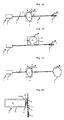
- the figure 1 a shows an identification device 1 which comprises an antenna control circuit 2, a main antenna 3, here of ferrite type, and electrical connection means for electrically connecting the control circuit 2 to the main antenna 3.
- the electrical connection means consist of a pair 4 of electrical wires which connect the control circuit 2 to the main antenna 3.
- the pair 4 of electrical wires makes it possible to convey the electrical signals of the main antenna 3 transmits electromagnetic signals S corresponding to the useful signals. These signals S are detectable by an identifying device (not shown) in a coverage area.
- the pair 4 of electrical wires may have a length of several meters so that the control circuit 2 can be located at the location of the vehicle where the identification device is present and that the antenna 3 can be located inside. an area to cover.
- the two electrical son are normally joined over their entire length for one hand, facilitate integration into the vehicle, and secondly, limit the magnetic field radiation.
- the two sons are, for example, joined.
- the two electrical wires of this pair 4 are advantageously twisted around each other on parts 5 and 6.
- the detorsed part 7 is made of so that the two son 8 and 9 of the pair 4 generally describe a form of O.
- other forms can be envisaged depending on the coverage area that is desired.
- the detorsed part 7 thus plays the role of a loop-type secondary antenna which emits electromagnetic signals detectable by the identifier around this part 7.
- secondary antenna are detectable by an identifier in a large area around the detorsed part.
- Each stranded portion 7 of particular shape corresponds to a transmission power and an impedance.
- the portion 7 of the son detoursadées 8 and 9 must not delimit a surface A too large so that the impedance formed by the pair 4 of son and the main antenna 3 is not too modified.
- the portion 7 being detoursadée must not change by more than 15% the total impedance of the antenna and the pair of 4 son. This limited modification of the total impedance allows the control circuit 2 to discharge the same current as that delivered when the pair 4 of electrical wires is completely twisted.
- the figure 1b shows an alternative embodiment of Figure la in which the detorsaded portion 7 is no longer formed from the two son 8 and 9 but from only one of the two son of the pair of electrical son 4. More specifically, in this embodiment, only one of the two son of the pair 4 is detorsadé so that the portion 7 delimits a surface.
- the surface A2 may be formed either by the wire 8 or by the wire 9 of the electrical pair 4.
- the two son 8 or 9 of the part 7 is still spaced apart from each other more than they are in the twisted parts 5 and 6.
- FIG. 1a and 1b show a variant of Figures 1a and 1b wherein the main antenna 3 is a loop antenna.
- the invention can be achieved by using connection means connecting any type of antenna to an antenna control circuit 2.
- the same pair of wires is used to make the main antenna 3, the secondary antenna 7, and the electrical connection between the control circuit 2 and the antennas 3 and 7.
- a loop-type secondary antenna is produced locally in series with the main antenna 3.
- This secondary antenna is produced with a zero cost since it is made from wires already present in the original system. which are arranged in a particular way.
- the invention does not require any additional electronic circuits.
- the control circuit 2 of the main antenna 3 allows control and feeding not only of the antenna main but also the secondary antenna 7.
- the signals emitted by the main antenna and the secondary antenna formed by part 7 are the same.
- Secondary antenna parts are here directly made from the pair 4 of electrical wires connecting the control circuit 2 to the main antenna 3, for example by locally detaching one or both of the electrical wires 8 and 9 so as to exclude these same sons of each other.
- these secondary antenna parts may comprise an electric wire, or two spaced apart wires, which are attached and connected on either side, either by welding, or by means of connectors, with two wires or two pairs of wires. electric wires respectively connected to the control circuit and to the main antenna.
- the figures 2 show examples of embodiments of secondary antenna parts 7 which are mounted on supports 14 or 15.
- one of the son of the pair 4 of electrical son is hooked to a support 14 of rectangular shape, so as to define a well-defined surface A3 between two ends of the two torsades 5.1 and 6.1.
- This well-defined surface makes it possible to calibrate the intensity of the magnetic field generated by the detoured portion forming a secondary antenna.
- the support 14 it is thus possible to industrially create parts 7 that have been uncoupled so that the surface formed delimited by these parts 7 is always the same from one vehicle to another and therefore the intensity of the signals transmitted by these secondary antennas are also the same from one vehicle to another.
- the support 14 makes it possible to precisely calibrate the intensity of the secondary antenna formed by a part 7 that is untwisted.
- the portion 7 detorsaded mounted on the support 14 has a U-shaped and is connected in series with one of the two son 8 or 9 of the pair 4 of son son.
- the support 14 is made from a flex-type cable which has been welded to the ends of two son located at the ends of this cable.
- this support 14 is a plastic support having a groove inside which the thread of part 7 is introduced.
- the shapes of part 7 and the support can be any and adapt to the shape of the area to be covered.
- the detorsed part 7 can be connected to the pair of wires 4 thanks to a connector assembly 16 and 17. Indeed, one of the wires of the pair 4 can be cut and connected to a connector 16 and the two ends of the wire of the stripped portion can be connected to a connector 17.
- the stripped portions 7 can be placed beforehand in areas where the electromagnetic signals are not detected by an identifier and connected to the pair 4 of electric wires at the last moment.
- the figure 2b shows a variant of the realization of the figure 2a .
- the two son of the pair 4 are untwisted and mounted on a support 15 so as to delimit a surface A4 which extends on either side of this pair 4, between ends of the two twists 5.1 and 6.1 .
- This configuration amounts to producing two parts 7 that have been untwined and described in the figure 2a .
- the two connectors 16 connect the ends of the twisted parts and the two connectors 17 connect the ends of the part 7 being untwisted.
- a first connector connects four ends of the twisted portions 5 and 6 and a second connector connects four ends of the detorsed portion 7.
- the support 15 may be a flex-type cable or a plastic plate having a groove.
- the figures 3 show the embodiment of the invention inside a passenger compartment 18 of a vehicle.
- the antenna coverage areas are represented in two dimensions but it is actually a volume that these coverage areas actually describe.
- the figure 3a shows an example of the state of the art in which a main antenna 3 for example ferrite type provides coverage of a main zone Z1.
- This main antenna 3 is connected to the control circuit 2 by conventional electrical connection means, namely a pair of electrical wires, preferably twisted over their entire length.
- Zone Z1 covers most of the volume interior of the passenger compartment 18 and extends slightly outside of this cabin 18.
- areas 19 and 20 hatched are not covered by the main antenna 3.
- These areas 19 and 20 here correspond to extreme parts of the passenger compartment 18, for example at the ends of a dashboard and at the ends of a rear shelf.
- the figure 3b shows an example of use of the invention in which the pair of wires connecting the main antenna 3 to the control circuit 2 has been untwisted in two places, so as to create two loops forming two secondary antennas which are electrically connected to each other. series with the main antenna 3 and whose coverage areas are referenced 21-22. Other locations could be provided to cover the rear areas.
- the zones 21-22 covered by these secondary antennas are much smaller than the zone Z1 covered by the main antenna 3 of ferrite type or loop type.
- the coverage areas of the secondary antennas each correspond to 10% of the coverage area of the main antenna.
- Detangling the pair of wires thus makes it possible to produce several antennas from a single main antenna. It is thus possible to achieve several zones 21-22 secondary coverage distinct from the Z1 coverage area of the main antenna to cover the overall volume of the passenger compartment 18 of the vehicle.
- the pair of wires is detorsed locally around a dashboard or inside a box separated from the passenger compartment by a metal wall which absorbs the low frequency electromagnetic signals, about 125 kHz, emitted by the main antenna 3.
- the pairs of wires can be untwisted in all the extreme or peripheral zones of the passenger compartment 18, such as a glove box, a sun visor, a bezel range, a nasturtium or storage compartments doors or trunk.
- the figures 4 show an example of coverage of the passenger compartment 18 of a vehicle with two main antennas 25 and 26, for example ferrite type.
- an area 29 of coverage of the main antenna 25 is hatched while on the figure 4b a zone 30 of coverage of the antenna 26 is hatched.
- the antenna 25 provides coverage of a front portion of the cockpit 18 while the antenna 26 provides coverage of a rear portion of the cockpit 18.
- these two areas 29 and 30 cover these antennas 25 and 26 therefore provide overall coverage of the interior volume of the passenger compartment 18, with a covering in the area 27 of the vehicle.
- the antennas 25 and 26 emit alternately.
- Non-coverage area may for example correspond to an area where there is a DVD player or car radio player with electronic circuits that emit disturbing signals.
- the pair of son connected to the antenna 26 which does not cover the area 28 to create a secondary antenna according to the invention is used here so that there is no overlap between the zone 28 covered by the undressed portion and the zone covered by the main antenna 26.
- detorsaded portions are made at locations, so that the area of coverage of the portion being undone does not overlap with the coverage area of the main antenna.
Landscapes
- Engineering & Computer Science (AREA)
- Mechanical Engineering (AREA)
- Support Of Aerials (AREA)
- Details Of Aerials (AREA)
- Electric Propulsion And Braking For Vehicles (AREA)
- Telephone Function (AREA)
- Lock And Its Accessories (AREA)
Claims (10)
- Identifizierungsvorrichtung (1) für ein Kraftfahrzeug mit einer Freisprech-Zugangs- und/oder Anlasseinrichtung, wobei die Vorrichtung eine Hauptantenne (3), eine elektronische Schaltung (2) zur Antennenüberwachung und elektrische Anschlussmittel (4, 8, 9) zur Verbindung der elektronischen Schaltung (2) mit der Hauptantenne (3) umfasst, dadurch gekennzeichnet, dass die elektrischen Anschlussmittel (4, 8, 9) mindestens eine elektrische Leitung (8, 9) umfassen, die so angeordnet ist, dass sie auf mindestens einem Abschnitt (7) eine Schleife bildet, die ein lokales Magnetfeld erzeugt und somit eine Hilfsantenne bildet.
- Vorrichtung nach Anspruch 1, dadurch gekennzeichnet, dass die elektrischen Anschlussmittel zwei elektrische Leitungen (8, 9) umfassen, die bei dem Abschnitt (7) voneinander beabstandet sind.
- Vorrichtung nach Anspruch 2, dadurch gekennzeichnet, dass die elektrischen Anschlussmittel (4, 8, 9) lediglich von den beiden elektrischen Leitungen (8, 9) gebildet sind, wobei die beiden elektrischen Leitungen außerhalb des Abschnitts zu einem Leitungspaar (4) mit schwacher elektromagnetischer Abstrahlung zusammengefasst sind.
- Vorrichtung nach Anspruch 3, dadurch gekennzeichnet, dass die beiden elektrischen Leitungen (8, 9) außerhalb des Abschnittes (7) miteinander verdrillt sind.
- Vorrichtung nach einem der Ansprüche 2 bis 4, dadurch gekennzeichnet, dass die beiden elektrischen Leitungen zudem zur Bildung der Hauptantenne (3) benutzt werden.
- Vorrichtung nach Anspruch 1, dadurch gekennzeichnet, dass der Abschnitt (7) mittels einer Schweißverbindung oder über Steckverbinder (16, 17) zur beidseitigen Verbindung der elektrischen Leitung mit zwei elektrischen Leitungen verbunden ist, die jeweils mit der Überwachungsschaltung (2) und der Hauptantenne (3) verbunden sind.
- Vorrichtung nach einem der Ansprüche 1 bis 6, dadurch gekennzeichnet, dass die elektrische Leitung bei dem Abschnitt (7) auf einem Träger (14, 15) gehaltert ist.
- Vorrichtung nach einem der vorhergehenden Ansprüche, dadurch gekennzeichnet, dass- die Hauptantenne elektromagnetische Signale (S) aussendet, die innerhalb einer ersten Abdeckungszone (Z1) von einer tragbaren Identifikationseinheit erfasst werden können,- der die Zweitantenne bildende Abschnitt elektromagnetische Signale aussendet, die von der Identifikationseinheit einer zweiten Abdeckungszone (21-22) erfasst werden können, die kleiner ist als die erste Abdeckungszone.
- Vorrichtung nach Anspruch 8, dadurch gekennzeichnet, dass die zweite Abdeckungszone insgesamt 10 % der ersten Abdeckungszone entspricht.
- Identifizierungsvorrichtung nach dem einem Ansprüche 8 oder 9, dadurch gekennzeichnet, dass der eine Hilfsantenne bildende Abschnitt an einer Stelle so ausgeführt ist, dass die zweite Abdeckungszone und die erste Abdeckungszone sich nicht überlappen.
Applications Claiming Priority (2)
| Application Number | Priority Date | Filing Date | Title |
|---|---|---|---|
| FR0403970A FR2869006B1 (fr) | 2004-04-16 | 2004-04-16 | Dispositif d'identification pour un vehicule automobile equipe d'un systeme d'acces et / ou demarrage dit mains libres |
| PCT/EP2005/051609 WO2005110824A1 (fr) | 2004-04-16 | 2005-04-12 | Dispositif d’identification pour un vehicule automobile equipe d’un systeme d’acces et / ou demarrage dit mains libres |
Publications (2)
| Publication Number | Publication Date |
|---|---|
| EP1740420A1 EP1740420A1 (de) | 2007-01-10 |
| EP1740420B1 true EP1740420B1 (de) | 2009-02-18 |
Family
ID=34945741
Family Applications (1)
| Application Number | Title | Priority Date | Filing Date |
|---|---|---|---|
| EP05729522A Expired - Lifetime EP1740420B1 (de) | 2004-04-16 | 2005-04-12 | Identifikationsvorrichtung für ein kraftfahrzeug mit einem handfreien zugang und/oder motorstartsystem |
Country Status (5)
| Country | Link |
|---|---|
| EP (1) | EP1740420B1 (de) |
| AT (1) | ATE423045T1 (de) |
| DE (1) | DE602005012816D1 (de) |
| FR (1) | FR2869006B1 (de) |
| WO (1) | WO2005110824A1 (de) |
Families Citing this family (1)
| Publication number | Priority date | Publication date | Assignee | Title |
|---|---|---|---|---|
| DE102012212418A1 (de) * | 2012-07-16 | 2014-01-30 | Brose Fahrzeugteile Gmbh & Co. Kg, Hallstadt | Sensoreinrichtung für ein Fahrzeug |
Family Cites Families (3)
| Publication number | Priority date | Publication date | Assignee | Title |
|---|---|---|---|---|
| US5883599A (en) * | 1997-01-16 | 1999-03-16 | Ford Motor Company | Antenna system for a motor vehicle |
| FR2794086B1 (fr) * | 1999-05-27 | 2001-08-24 | Valeo Securite Habitacle | Dispositif de commande de verrouillage d'un vehicule |
| FR2810946B3 (fr) * | 2000-07-03 | 2002-04-19 | Valeo Electronique | Vehicule automobile equipe d'un systeme d'acces dit "mains libres" perfectionne pour localiser un badge portatif |
-
2004
- 2004-04-16 FR FR0403970A patent/FR2869006B1/fr not_active Expired - Lifetime
-
2005
- 2005-04-12 AT AT05729522T patent/ATE423045T1/de not_active IP Right Cessation
- 2005-04-12 WO PCT/EP2005/051609 patent/WO2005110824A1/fr not_active Ceased
- 2005-04-12 DE DE602005012816T patent/DE602005012816D1/de not_active Expired - Lifetime
- 2005-04-12 EP EP05729522A patent/EP1740420B1/de not_active Expired - Lifetime
Also Published As
| Publication number | Publication date |
|---|---|
| ATE423045T1 (de) | 2009-03-15 |
| EP1740420A1 (de) | 2007-01-10 |
| FR2869006B1 (fr) | 2006-07-14 |
| WO2005110824A1 (fr) | 2005-11-24 |
| FR2869006A1 (fr) | 2005-10-21 |
| DE602005012816D1 (de) | 2009-04-02 |
Similar Documents
| Publication | Publication Date | Title |
|---|---|---|
| FR2607984A1 (fr) | Systeme de commande de regulateurs de glaces motorisees de vehicule | |
| WO2016015848A1 (fr) | Dispositif de communication radiofrequence en champ proche avec un element portable embarque dans un vehicule automobile | |
| EP1740420B1 (de) | Identifikationsvorrichtung für ein kraftfahrzeug mit einem handfreien zugang und/oder motorstartsystem | |
| WO2021110309A1 (fr) | Dispositif de communication en champ proche a haute frequence et de rechargement par induction d'un appareil electronique portable | |
| FR2833292A1 (fr) | Systeme de detection de presence d'un utilisateur notamment pour vehicule automobile | |
| WO2019238696A1 (fr) | Dispositif de communication en champ proche a haute frequence et de rechargement par induction d'un appareil electronique portable | |
| FR2755925A1 (fr) | Equipement de vehicule automobile comprenant un dispositif antivol et un dispositif a telecommande | |
| EP1363354B1 (de) | Fahrzeug mit einer Vorrichtung zur Übertragung von Signalen | |
| EP2747039B1 (de) | Kraftfahrzeugsfernbedienung mit Unterdrückungsvorrichtung für magnetische Kupplung | |
| FR2828286A1 (fr) | Dispositif de diagnostic pour une antenne | |
| EP1132999B1 (de) | Kraftfahrzeug mit Antenne für ein angepasstes Kommunikationssystem | |
| EP3560043B1 (de) | Elektrische anordnung für ein kraftfahrzeug mit einem koaxialkabel und elektrische anschlussklemme | |
| FR2734119A1 (fr) | Appareil de commande notamment pour commander les fonctions d'un vehicule automobile | |
| FR2689688A1 (fr) | Aérien pour l'utilisation de plusieurs appareils émetteurs et/ou récepteurs notamment pour véhicules automobiles. | |
| BE1007985A5 (fr) | Installation de telecommande, notamment pour l'ouverture et/ou la fermeture de portes, de garage ou de vehicules automobiles. | |
| FR2866156A1 (fr) | Antenne serigraphiee pour lunette arriere et lunette de custode de vehicule automobile de type break. | |
| EP3365940A1 (de) | Touchscreen-anzeigevorrichtung mit reduzierter elektromagnetischer störstrahlenemission | |
| FR2808125A1 (fr) | Vehicule automobile equipe d'une antenne exploitee pour un systeme d'acces mains libres | |
| EP3729924B1 (de) | Hochspannungsladegerät an bord eines hybrid- oder elektromotorfahrzeugs mit einer kapazitiven filtervorrichtung | |
| KR102410861B1 (ko) | 글래스 배선 장치 및 이를 포함하는 차량 | |
| FR3072461A1 (fr) | Capteur pour la mesure d'un courant de sortie d'un systeme electrique | |
| FR2936753A1 (fr) | Systeme de vision arriere notamment pour vehicule automobile et vehicule automobile comportant un tel systeme | |
| EP1074425A1 (de) | Vorrichtung zur Übertragung von Signalen zwischen einer Überwachung und Steuereinheit eines Kraftfahrzeuges und eine auf einer Unterbaugruppe montierte Einrichtung | |
| FR2992505A1 (fr) | Dispositif de communication par voie d'ondes a emission et/ou reception renforcee(s) au voisinage de cable(s) electrique(s) d'un systeme | |
| FR2852170A1 (fr) | Dispositif d'emission et/ou de reception et systeme de securisation integrant un tel dispositif |
Legal Events
| Date | Code | Title | Description |
|---|---|---|---|
| PUAI | Public reference made under article 153(3) epc to a published international application that has entered the european phase |
Free format text: ORIGINAL CODE: 0009012 |
|
| 17P | Request for examination filed |
Effective date: 20061116 |
|
| AK | Designated contracting states |
Kind code of ref document: A1 Designated state(s): AT BE BG CH CY CZ DE DK EE ES FI FR GB GR HU IE IS IT LI LT LU MC NL PL PT RO SE SI SK TR |
|
| DAX | Request for extension of the european patent (deleted) | ||
| GRAP | Despatch of communication of intention to grant a patent |
Free format text: ORIGINAL CODE: EPIDOSNIGR1 |
|
| GRAS | Grant fee paid |
Free format text: ORIGINAL CODE: EPIDOSNIGR3 |
|
| GRAA | (expected) grant |
Free format text: ORIGINAL CODE: 0009210 |
|
| AK | Designated contracting states |
Kind code of ref document: B1 Designated state(s): AT BE BG CH CY CZ DE DK EE ES FI FR GB GR HU IE IS IT LI LT LU MC NL PL PT RO SE SI SK TR |
|
| REG | Reference to a national code |
Ref country code: GB Ref legal event code: FG4D Free format text: NOT ENGLISH |
|
| REG | Reference to a national code |
Ref country code: CH Ref legal event code: EP |
|
| REG | Reference to a national code |
Ref country code: IE Ref legal event code: FG4D Free format text: LANGUAGE OF EP DOCUMENT: FRENCH |
|
| REF | Corresponds to: |
Ref document number: 602005012816 Country of ref document: DE Date of ref document: 20090402 Kind code of ref document: P |
|
| PG25 | Lapsed in a contracting state [announced via postgrant information from national office to epo] |
Ref country code: ES Free format text: LAPSE BECAUSE OF FAILURE TO SUBMIT A TRANSLATION OF THE DESCRIPTION OR TO PAY THE FEE WITHIN THE PRESCRIBED TIME-LIMIT Effective date: 20090529 Ref country code: FI Free format text: LAPSE BECAUSE OF FAILURE TO SUBMIT A TRANSLATION OF THE DESCRIPTION OR TO PAY THE FEE WITHIN THE PRESCRIBED TIME-LIMIT Effective date: 20090218 Ref country code: NL Free format text: LAPSE BECAUSE OF FAILURE TO SUBMIT A TRANSLATION OF THE DESCRIPTION OR TO PAY THE FEE WITHIN THE PRESCRIBED TIME-LIMIT Effective date: 20090218 Ref country code: SI Free format text: LAPSE BECAUSE OF FAILURE TO SUBMIT A TRANSLATION OF THE DESCRIPTION OR TO PAY THE FEE WITHIN THE PRESCRIBED TIME-LIMIT Effective date: 20090218 Ref country code: LT Free format text: LAPSE BECAUSE OF FAILURE TO SUBMIT A TRANSLATION OF THE DESCRIPTION OR TO PAY THE FEE WITHIN THE PRESCRIBED TIME-LIMIT Effective date: 20090218 |
|
| NLV1 | Nl: lapsed or annulled due to failure to fulfill the requirements of art. 29p and 29m of the patents act | ||
| PG25 | Lapsed in a contracting state [announced via postgrant information from national office to epo] |
Ref country code: SE Free format text: LAPSE BECAUSE OF FAILURE TO SUBMIT A TRANSLATION OF THE DESCRIPTION OR TO PAY THE FEE WITHIN THE PRESCRIBED TIME-LIMIT Effective date: 20090518 Ref country code: PL Free format text: LAPSE BECAUSE OF FAILURE TO SUBMIT A TRANSLATION OF THE DESCRIPTION OR TO PAY THE FEE WITHIN THE PRESCRIBED TIME-LIMIT Effective date: 20090218 Ref country code: IS Free format text: LAPSE BECAUSE OF FAILURE TO SUBMIT A TRANSLATION OF THE DESCRIPTION OR TO PAY THE FEE WITHIN THE PRESCRIBED TIME-LIMIT Effective date: 20090618 Ref country code: AT Free format text: LAPSE BECAUSE OF FAILURE TO SUBMIT A TRANSLATION OF THE DESCRIPTION OR TO PAY THE FEE WITHIN THE PRESCRIBED TIME-LIMIT Effective date: 20090218 |
|
| REG | Reference to a national code |
Ref country code: IE Ref legal event code: FD4D |
|
| PG25 | Lapsed in a contracting state [announced via postgrant information from national office to epo] |
Ref country code: IE Free format text: LAPSE BECAUSE OF FAILURE TO SUBMIT A TRANSLATION OF THE DESCRIPTION OR TO PAY THE FEE WITHIN THE PRESCRIBED TIME-LIMIT Effective date: 20090218 Ref country code: EE Free format text: LAPSE BECAUSE OF FAILURE TO SUBMIT A TRANSLATION OF THE DESCRIPTION OR TO PAY THE FEE WITHIN THE PRESCRIBED TIME-LIMIT Effective date: 20090218 Ref country code: CZ Free format text: LAPSE BECAUSE OF FAILURE TO SUBMIT A TRANSLATION OF THE DESCRIPTION OR TO PAY THE FEE WITHIN THE PRESCRIBED TIME-LIMIT Effective date: 20090218 Ref country code: PT Free format text: LAPSE BECAUSE OF FAILURE TO SUBMIT A TRANSLATION OF THE DESCRIPTION OR TO PAY THE FEE WITHIN THE PRESCRIBED TIME-LIMIT Effective date: 20090727 Ref country code: DK Free format text: LAPSE BECAUSE OF FAILURE TO SUBMIT A TRANSLATION OF THE DESCRIPTION OR TO PAY THE FEE WITHIN THE PRESCRIBED TIME-LIMIT Effective date: 20090218 |
|
| BERE | Be: lapsed |
Owner name: VALEO SECURITE HABITACLE S.A.S. Effective date: 20090430 |
|
| PG25 | Lapsed in a contracting state [announced via postgrant information from national office to epo] |
Ref country code: SK Free format text: LAPSE BECAUSE OF FAILURE TO SUBMIT A TRANSLATION OF THE DESCRIPTION OR TO PAY THE FEE WITHIN THE PRESCRIBED TIME-LIMIT Effective date: 20090218 Ref country code: RO Free format text: LAPSE BECAUSE OF FAILURE TO SUBMIT A TRANSLATION OF THE DESCRIPTION OR TO PAY THE FEE WITHIN THE PRESCRIBED TIME-LIMIT Effective date: 20090218 |
|
| PGFP | Annual fee paid to national office [announced via postgrant information from national office to epo] |
Ref country code: GB Payment date: 20090407 Year of fee payment: 5 |
|
| REG | Reference to a national code |
Ref country code: CH Ref legal event code: PL |
|
| PLBE | No opposition filed within time limit |
Free format text: ORIGINAL CODE: 0009261 |
|
| STAA | Information on the status of an ep patent application or granted ep patent |
Free format text: STATUS: NO OPPOSITION FILED WITHIN TIME LIMIT |
|
| 26N | No opposition filed |
Effective date: 20091119 |
|
| PG25 | Lapsed in a contracting state [announced via postgrant information from national office to epo] |
Ref country code: LI Free format text: LAPSE BECAUSE OF NON-PAYMENT OF DUE FEES Effective date: 20090430 Ref country code: BG Free format text: LAPSE BECAUSE OF FAILURE TO SUBMIT A TRANSLATION OF THE DESCRIPTION OR TO PAY THE FEE WITHIN THE PRESCRIBED TIME-LIMIT Effective date: 20090518 Ref country code: CH Free format text: LAPSE BECAUSE OF NON-PAYMENT OF DUE FEES Effective date: 20090430 |
|
| PG25 | Lapsed in a contracting state [announced via postgrant information from national office to epo] |
Ref country code: MC Free format text: LAPSE BECAUSE OF NON-PAYMENT OF DUE FEES Effective date: 20090430 |
|
| PG25 | Lapsed in a contracting state [announced via postgrant information from national office to epo] |
Ref country code: BE Free format text: LAPSE BECAUSE OF NON-PAYMENT OF DUE FEES Effective date: 20090430 |
|
| PG25 | Lapsed in a contracting state [announced via postgrant information from national office to epo] |
Ref country code: GR Free format text: LAPSE BECAUSE OF FAILURE TO SUBMIT A TRANSLATION OF THE DESCRIPTION OR TO PAY THE FEE WITHIN THE PRESCRIBED TIME-LIMIT Effective date: 20090519 |
|
| GBPC | Gb: european patent ceased through non-payment of renewal fee |
Effective date: 20100412 |
|
| PG25 | Lapsed in a contracting state [announced via postgrant information from national office to epo] |
Ref country code: GB Free format text: LAPSE BECAUSE OF NON-PAYMENT OF DUE FEES Effective date: 20100412 Ref country code: IT Free format text: LAPSE BECAUSE OF FAILURE TO SUBMIT A TRANSLATION OF THE DESCRIPTION OR TO PAY THE FEE WITHIN THE PRESCRIBED TIME-LIMIT Effective date: 20090218 |
|
| PG25 | Lapsed in a contracting state [announced via postgrant information from national office to epo] |
Ref country code: LU Free format text: LAPSE BECAUSE OF NON-PAYMENT OF DUE FEES Effective date: 20090412 |
|
| PG25 | Lapsed in a contracting state [announced via postgrant information from national office to epo] |
Ref country code: HU Free format text: LAPSE BECAUSE OF FAILURE TO SUBMIT A TRANSLATION OF THE DESCRIPTION OR TO PAY THE FEE WITHIN THE PRESCRIBED TIME-LIMIT Effective date: 20090819 |
|
| PG25 | Lapsed in a contracting state [announced via postgrant information from national office to epo] |
Ref country code: TR Free format text: LAPSE BECAUSE OF FAILURE TO SUBMIT A TRANSLATION OF THE DESCRIPTION OR TO PAY THE FEE WITHIN THE PRESCRIBED TIME-LIMIT Effective date: 20090218 |
|
| PG25 | Lapsed in a contracting state [announced via postgrant information from national office to epo] |
Ref country code: CY Free format text: LAPSE BECAUSE OF FAILURE TO SUBMIT A TRANSLATION OF THE DESCRIPTION OR TO PAY THE FEE WITHIN THE PRESCRIBED TIME-LIMIT Effective date: 20090218 |
|
| REG | Reference to a national code |
Ref country code: FR Ref legal event code: PLFP Year of fee payment: 12 |
|
| REG | Reference to a national code |
Ref country code: FR Ref legal event code: PLFP Year of fee payment: 13 |
|
| PGFP | Annual fee paid to national office [announced via postgrant information from national office to epo] |
Ref country code: DE Payment date: 20170412 Year of fee payment: 13 Ref country code: FR Payment date: 20170428 Year of fee payment: 13 |
|
| REG | Reference to a national code |
Ref country code: DE Ref legal event code: R119 Ref document number: 602005012816 Country of ref document: DE |
|
| PG25 | Lapsed in a contracting state [announced via postgrant information from national office to epo] |
Ref country code: DE Free format text: LAPSE BECAUSE OF NON-PAYMENT OF DUE FEES Effective date: 20181101 |
|
| PG25 | Lapsed in a contracting state [announced via postgrant information from national office to epo] |
Ref country code: FR Free format text: LAPSE BECAUSE OF NON-PAYMENT OF DUE FEES Effective date: 20180430 |