EP1740456B1 - Flugzeugstrahltriebwerk mit verbesserter aerodynamischer installation - Google Patents
Flugzeugstrahltriebwerk mit verbesserter aerodynamischer installation Download PDFInfo
- Publication number
- EP1740456B1 EP1740456B1 EP05758188A EP05758188A EP1740456B1 EP 1740456 B1 EP1740456 B1 EP 1740456B1 EP 05758188 A EP05758188 A EP 05758188A EP 05758188 A EP05758188 A EP 05758188A EP 1740456 B1 EP1740456 B1 EP 1740456B1
- Authority
- EP
- European Patent Office
- Prior art keywords
- angle
- axis
- cowlings
- downstream
- engine
- Prior art date
- Legal status (The legal status is an assumption and is not a legal conclusion. Google has not performed a legal analysis and makes no representation as to the accuracy of the status listed.)
- Expired - Lifetime
Links
Images

Classifications
-
- B—PERFORMING OPERATIONS; TRANSPORTING
- B64—AIRCRAFT; AVIATION; COSMONAUTICS
- B64D—EQUIPMENT FOR FITTING IN OR TO AIRCRAFT; FLIGHT SUITS; PARACHUTES; ARRANGEMENT OR MOUNTING OF POWER PLANTS OR PROPULSION TRANSMISSIONS IN AIRCRAFT
- B64D29/00—Power-plant nacelles, fairings or cowlings
- B64D29/08—Inspection panels for power plants
-
- B—PERFORMING OPERATIONS; TRANSPORTING
- B64—AIRCRAFT; AVIATION; COSMONAUTICS
- B64D—EQUIPMENT FOR FITTING IN OR TO AIRCRAFT; FLIGHT SUITS; PARACHUTES; ARRANGEMENT OR MOUNTING OF POWER PLANTS OR PROPULSION TRANSMISSIONS IN AIRCRAFT
- B64D29/00—Power-plant nacelles, fairings or cowlings
Definitions
- the present invention relates, in general, to a turbo-propulsion unit for an aircraft comprising in particular, from upstream to downstream with reference to the direction of flow of the gases, a reactor provided with a fan casing and a gas ejection system, coaxial with an engine axis, said gas ejection system including two half-cowlings of hindquarters, said D-ducts, each articulated about an axis, which allows them to pass , for maintenance purposes, from a closed position to an open position.
- said half-underbody cowlings are furthermore connected to the downstream end of the fan casing via means for sealing and transmitting forces, having complementary female and male profiles, "V-blade / V-groove" (V-blade / V-groove), the male profile belonging to the rear half-cowlings and the female profile belonging to the fan-blade side.
- V-blade / V-groove V-blade / V-groove
- a turbo-propulsion unit according to the preambles of claim 1 and 4 is known from document EP-A-1,174,341 .
- the document EP-A-0 744 339 shows a half-cowling of a nacelle where the angle ⁇ is between 2 ° and 7 °. However, it is not a half-rear body cowling connected to the fan case. In addition, the angle ⁇ of the junction plane is not mentioned.
- the axes of articulation diverge towards the downstream.
- the document US-A-5,203,525 shows two half-cowls arranged on the engine by means of two displaced axes of articulation; said axes being apparently parallel to the axis of the motor and to each other.
- the downstream outlet plane of the fan casing is strictly perpendicular to the motor axis and the axes of articulation of the half-cowls are parallel to each other and inclined at an angle ⁇ with respect to the motor axis.
- angle which can not exceed 2 to 3 ° because, beyond, the system "V-blade / V-groove" would have difficulty to engage properly due to a "chisel” effect and, moreover, the Increased friction resulting from such a difficult engagement would result in premature wear.
- the present invention provides a solution for such an increase in the angle ⁇ while maintaining proper operation of the system "V-blade / V-groove".
- the angle ⁇ that the hinge axes make with the motor axis is greater than 3 ° and the junction plane between the rear body half-cowls and the downstream end of the housing. blower is, with the plane perpendicular to the motor axis, an angle ⁇ such that the difference between the angle ⁇ and the angle ⁇ is less than or equal to about 3 °.
- the angle ⁇ is preferably less than or equal to 6 °.
- the axes of articulation of the rear-body half-cowls are fixed to a pylon, which is a streamlined structure integrated into the structure of said wing and, in the known art, the axes of articulation are strictly parallel to each other and to the axis of the pylon.
- the invention proposes in addition to the increase of the angle ⁇ and the inclination ⁇ of the plane of the system "V-blade / V- groove ", or alternatively to these means, to make said hinge axes converge towards each other in the downstream direction.
- the angle of convergence, with respect to the axis of the pylon, is preferably of the order of 1 °, the hinge pins making, therefore, between them, an angle of the order of 2 °.
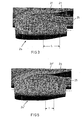
- the figure 1 represents a propulsion system according to the prior art and which shows the air inlet 1, the fan or fan 2, the fan casing 3, the compressors 4, the combustion chamber 5, the turbine casing 6 and the exhaust nozzle which is a common exhaust nozzle (mixed hot and cold gases), commonly called CNA, according to the English nomenclature "common nozzle assembly”.
- CNA common exhaust nozzle
- the system comprises, in addition, a two-part engine cover 9a, 9b and a two-part rear body cover 10a, 10b adapted to surround the assembly formed by the compressors 4, the combustion chamber 5 and the casing turbine 6, the division into two parts of the engine hood and the rear body cowling being made in a substantially vertical section plane.
- Each rear-body half-cowl 10a, 10b commonly referred to as D-duct, has three aerodynamic surfaces or skins, namely an outer nacelle surface 11, an outer fan duct surface 12 and an inner duct surface. Blower 13.
- the surfaces 12 and 13 define a half-blower channel (cold flow), respectively, 14a and 14b.
- the CNA 7 which, in normal operation, is connected to the rear body half-cowls, has two aerodynamic surfaces, namely the outer surface of the nacelle 15 and the inner surface of the hot and cold flow channel. 16. Thrust reverser doors 17 are implanted in the cowling 10a, 10b to act on the cold flow.
- the engine bonnet and the rear body bonnet are each formed of two halves, respectively 9a, 9b and 10a, 10b, but the common nozzle or CNA 7 is in one piece.
- the half-covers 9a, 9b and the half-cowlings 10a, 10b are mounted articulated on the driving beam (not shown) by means of hinges, respectively 18 and 19.
- the half-cowls 9a, 9b and the half-cowlings 10a, 10b comprise locks such as 20 and 21 for locking them in the closed position. It is understood that this assembly in two articulated parts is intended to allow easier access to the cold and hot parts of the reactor.
- V-blade / V-groove whose position on the upstream end of the half-cowling 10b is indicated at 22, for connection to the fan casing 3.
- Complementary structures, such as 23 ( figure 2 ) are positioned vis-a-vis on said housing.
- the plane of junction ZZ '(Z 1 -Z 1 ' to figure 4 ) of the "V-blade / V-groove" system merges with a plane YY 'perpendicular to the axis XX' of the engine so that the angle ⁇ 1 ( figure 4 ) between the two planes is zero.
- V-blade / V-groove A similar "V-blade / V-groove" system is provided between the downstream edge of the half-cowlings 10a, 10b and the upstream edge of the DAC 7 and, in this case also, the joining plane of the "V-blade” system. / V-groove "merges with a plane perpendicular to the axis XX 'of the engine.
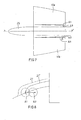
- the figure 3 shows a nacelle 24 mounted on a pylon 25 depending on the wing 26 of an aircraft.
- a zone, indicated at 27, of length L protrudes with respect to the general profile of the nacelle 24. This is due to the presence of the fairing of the hinges 19, which are arranged along an axis of articulation A1 ( figure 4 ) which makes an angle ⁇ 1 ⁇ 3 ° with the axis XX 'of the motor.
- this angle is brought to ⁇ 2 > 3, so that the axis of articulation now occupies the position A 2 and, simultaneously, it is given an angle ⁇ 2 to the junction plane of the "V" system. blade / V-groove ", thus becoming Z 2 -Z 2 ', with respect to the plane YY'.
- This angle ⁇ 2 is such that ⁇ 2 - ⁇ 2 ⁇ 3.
- the joining plane of the "V-blade / V-groove" system between the downstream edge of the rear body half-cowlings 10a, 10b and the upstream edge of the CNA 7 must, according to the invention. , be inclined at an angle ⁇ 2 , relative to the plane perpendicular to the axis XX 'of the engine, as is the joining plane of the system "V-blade / V-groove" between the upstream edge of the half-cowlings 10a, 10b and the downstream edge of the fan casing 3.
- the projection can be further reduced by using another measure illustrated Figures 7 and 8 .
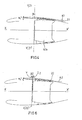
- the figure 7 shows schematically the pylon 25 and the two half-cowlings of the rear body 10a, 10b with their axes of articulation.
- the hinge pins occupy the position A1, that is to say they are parallel to each other and parallel to the longitudinal axis PP 'of the pylon 25. At this position corresponds the projection illustrated in 27 to figures 3 , 4 and 8 .
Landscapes
- Engineering & Computer Science (AREA)
- Aviation & Aerospace Engineering (AREA)
- Structures Of Non-Positive Displacement Pumps (AREA)
Claims (5)
- Turboprop-Triebwerk für Luftfahrzeug, umfassend insbesondere, von stromauf nach stromab bezüglich der Strömungsrichtung der Gase, ein Strahltriebwerk, das mit einem Gebläsegehäuse (3) versehen ist, und ein Gasausstoßsystem, die zu einer Motorachse (X-X') koaxial sind, wobei das Gasausstoßsystem zwei Heckverkleidungshälften (10a, 10b) einschließt, die jeweils um eine Achse angelenkt sind, was ihnen gestattet, von einer offenen Wartungsstellung in eine geschlossene Stellung überzugehen, in der die Heckverkleidungshälften (10a, 10b) außerdem mit dem stromab gelegenen Ende des Gebläsegehäuses (3) über ein Dichtungs- und Kraftübertragungsmittel (21, 23), "V-blade/V-groove" genannt, verbunden sind, wobei die Gelenkachse mit der Motorachse einen Winkel α bilden, dadurch gekennzeichnet, dass dieser Winkel α größer als 3° ist und dass die Trennebene (Z2-Z2') zwischen den Heckverkleidungshälften und dem stromab gelegenen Ende des Gebläsegehäuses (3) mit der zur Motorachse (X-X') senkrechten Ebene einen solchen Winkel β bildet, dass die Differenz zwischen dem Winkel α und dem Winkel β kleiner als oder gleich 3° ist.
- Turboprop-Triebwerk nach Anspruch 1, dadurch gekennzeichnet, dass der Winkel α kleiner als oder gleich 6° ist.
- Turboprop-Triebwerk nach Anspruch 1 oder 2, das unter dem Tragwerk montiert ist und bei dem die Gelenkachsen an einer in die Struktur des Tragwerks (26) integrierten Stütze (25) befestigt sind, dadurch gekennzeichnet, dass die Gelenkachsen (A2) in Richtung stromab aufeinander zu konvergieren.
- Turboprop-Triebwerk für Luftfahrzeug, umfassend insbesondere, von stromauf nach stromab bezüglich der Strömungsrichtung der Gase, ein Strahltriebwerk, das mit einem Gebläsegehäuse (3) versehen ist, und ein Gasausstoßsystem, die zu einer Motorachse (X-X') koaxial sind, wobei dieses Gasausstoßsystem zwei Heckverkleidungshälften (10a, 10b) einschließt, die jeweils um eine Achse angelenkt sind, was ihnen gestattet, von einer offenen Wartungsstellung in eine geschlossene Stellung überzugehen, in der die Heckverkleidungshälften (10a, 10b) außerdem mit dem stromab gelegenen Ende des Gebläsegehäuses (3) über ein Dichtungs- und Kraftübertragungsmittel (21, 23), "V-blade/V-groove" genannt, verbunden sind, wobei die Gelenkachsen an einer in die Struktur des Tragwerks (26) integrierten Stütze (25) befestigt sind, dadurch gekennzeichnet, dass die Gelenkachsen (A3) in Richtung stromab aufeinander zu konvergieren
- Turboprop-Triebwerk nach Anspruch 3 oder 4, dadurch gekennzeichnet, dass der Konvergenzwinkel (δ) bezüglich der Achse der Stütze etwa 1° beträgt.
Applications Claiming Priority (2)
| Application Number | Priority Date | Filing Date | Title |
|---|---|---|---|
| FR0404445A FR2869290B1 (fr) | 2004-04-27 | 2004-04-27 | Groupe turbopropulseur pour aeronef a installation aerodynamique amelioree |
| PCT/FR2005/000940 WO2005110845A1 (fr) | 2004-04-27 | 2005-04-19 | Groupe turbopropulseur pour aeronef a installation aerodynamique amelioree |
Publications (2)
| Publication Number | Publication Date |
|---|---|
| EP1740456A1 EP1740456A1 (de) | 2007-01-10 |
| EP1740456B1 true EP1740456B1 (de) | 2008-03-26 |
Family
ID=34949288
Family Applications (1)
| Application Number | Title | Priority Date | Filing Date |
|---|---|---|---|
| EP05758188A Expired - Lifetime EP1740456B1 (de) | 2004-04-27 | 2005-04-19 | Flugzeugstrahltriebwerk mit verbesserter aerodynamischer installation |
Country Status (6)
| Country | Link |
|---|---|
| US (1) | US7681833B2 (de) |
| EP (1) | EP1740456B1 (de) |
| CA (1) | CA2564619A1 (de) |
| DE (1) | DE602005005659T2 (de) |
| FR (1) | FR2869290B1 (de) |
| WO (1) | WO2005110845A1 (de) |
Families Citing this family (10)
| Publication number | Priority date | Publication date | Assignee | Title |
|---|---|---|---|---|
| FR2896481B1 (fr) * | 2006-01-23 | 2009-12-04 | Aircelle Sa | Systeme de fixation pour element constitutif d'une nacelle de turboreacteur |
| US20080258016A1 (en) * | 2007-04-23 | 2008-10-23 | Gukeisen Robert L | Nacelle assembly without lower bi-fi splitter |
| FR2920215B1 (fr) * | 2007-08-20 | 2009-12-04 | Aircelle Sa | Joint d'etancheite a grande amplitude d'ecrasement |
| FR2925120B1 (fr) * | 2007-12-18 | 2010-02-19 | Snecma | Extension de carter intermediaire pour turboreacteur d'aeronef, comprenant une rainure annulaire sectorisee de reception des capots de nacelle |
| FR2994216B1 (fr) * | 2012-08-02 | 2014-09-05 | Snecma | Partie de revolution de carter intermediaire comportant un insert dispose dans une rainure annulaire |
| US9410441B2 (en) | 2012-09-13 | 2016-08-09 | Pratt & Whitney Canada Corp. | Turboprop engine with compressor turbine shroud |
| US9989009B2 (en) * | 2012-10-31 | 2018-06-05 | The Boeing Company | Methods and apparatus for sealing variable area fan nozzles of jet engines |
| US11613372B2 (en) * | 2020-11-09 | 2023-03-28 | Rohr, Inc. | Ducted fan case attachment structure |
| FR3117173B1 (fr) | 2020-12-09 | 2025-03-28 | Safran Aircraft Engines | Ensemble propulsif d’aéronef et procédé d’adaptation d’un ensemble propulsif |
| FR3121709B1 (fr) | 2021-04-08 | 2023-05-05 | Safran Aircraft Engines | Virole extérieure de carter intermédiaire en matériau composite, pour turbomachine d’aéronef |
Family Cites Families (6)
| Publication number | Priority date | Publication date | Assignee | Title |
|---|---|---|---|---|
| US5203525A (en) * | 1991-10-23 | 1993-04-20 | Rohr, Inc. | Hinge with offset pivot line |
| GB9407632D0 (en) * | 1994-04-18 | 1994-06-08 | Short Brothers Plc | An aircraft propulsive power unit |
| WO1996020111A1 (en) * | 1994-12-23 | 1996-07-04 | United Technologies Corporation | A mounting arrangement for a gas turbine engine |
| FR2734540B1 (fr) * | 1995-05-24 | 1997-08-08 | Aerospatiale | Nacelle de moteur d'aeronef comportant un capot de nacelle |
| FR2771710B1 (fr) * | 1997-12-03 | 2000-02-11 | Aerospatiale | Dispositif d'ouverture commun a deux capots adjacents de nacelle de moteur d'avion |
| FR2811716B1 (fr) * | 2000-07-17 | 2002-10-04 | Hurel Dubois Avions | Perfectionnements aux arriere-corps de nacelle, a tuyere commune, de reacteur d'avion |
-
2004
- 2004-04-27 FR FR0404445A patent/FR2869290B1/fr not_active Expired - Fee Related
-
2005
- 2005-04-19 DE DE602005005659T patent/DE602005005659T2/de not_active Expired - Lifetime
- 2005-04-19 CA CA002564619A patent/CA2564619A1/fr not_active Abandoned
- 2005-04-19 US US11/587,355 patent/US7681833B2/en not_active Expired - Fee Related
- 2005-04-19 WO PCT/FR2005/000940 patent/WO2005110845A1/fr not_active Ceased
- 2005-04-19 EP EP05758188A patent/EP1740456B1/de not_active Expired - Lifetime
Also Published As
| Publication number | Publication date |
|---|---|
| CA2564619A1 (fr) | 2005-11-24 |
| FR2869290A1 (fr) | 2005-10-28 |
| FR2869290B1 (fr) | 2006-07-21 |
| DE602005005659D1 (de) | 2008-05-08 |
| US7681833B2 (en) | 2010-03-23 |
| DE602005005659T2 (de) | 2009-06-18 |
| WO2005110845A1 (fr) | 2005-11-24 |
| EP1740456A1 (de) | 2007-01-10 |
| US20070217913A1 (en) | 2007-09-20 |
Similar Documents
| Publication | Publication Date | Title |
|---|---|---|
| EP2651764B1 (de) | Gondel für eine bypassgasturbine | |
| EP3415749B1 (de) | Gondel mit schubumkehrsystem, das begrenzte aerodynamische störungen aufweist | |
| FR2999239A1 (fr) | Inverseur de poussee de nacelle et nacelle equipee d'au moins un inverseur | |
| EP1740456B1 (de) | Flugzeugstrahltriebwerk mit verbesserter aerodynamischer installation | |
| EP1174341B1 (de) | Verbesserung zum Heckejektorteil einer Gondel mit gemeinsamer Schubdüse für ein Flugzeugtriebswerk | |
| EP2188177A1 (de) | Befestigung einer triebwerksgondelstruktur mittels einer verstärkten messerschneiden-rillen-kupplung | |
| FR2908470A1 (fr) | Ensemble de tuyere de turboreacteur double flux | |
| EP3719293B1 (de) | Turboreaktor, der eine mit einem schubumkehrsystem und einem beweglichen kaskadengitter ausgestattete gondel umfasst | |
| FR2953490A1 (fr) | Ensemble arriere de nacelle pour turboreacteur | |
| FR2676780A1 (fr) | Inverseur de poussee pour turbosoufflante a tres grand taux dilution. | |
| WO2010061071A2 (fr) | Nacelle integree sur aile volante | |
| EP3891374B1 (de) | Schubumkehrvorrichtung mit einer leichten schubumkehrklappe | |
| EP4100639A1 (de) | Vorrichtung zum befestigen eines pleuelstangenschenkels für eine schubumkehr-kaskadenklappe | |
| EP3539878B1 (de) | Turbotriebwerk, das eine gondel umfasst, die mit einem gebläsegehäuse und einer festen struktur ausgestattet ist | |
| FR3125093A1 (fr) | Bielle pour nacelle de turbomachine | |
| WO2018002560A1 (fr) | Agencement pour la fixation d'une bielle de volet d'inversion de poussée sur une structure interne fixe d'une nacelle de turboréacteur et procédé de montage/démontage associé | |
| FR3066788B1 (fr) | Moteur pour aeronef comprenant au moins un actionneur de systeme d'inversion de poussee agence dans un cone d'ejection des gaz | |
| EP4173961A1 (de) | Flugzeuggondel mit einer verbindung zwischen durchgängen mit nach innen gerichteten flanschen und flugzeug mit mindestens einer solchen gondel | |
| EP4331993A1 (de) | Antriebseinheit für ein flugzeug | |
| EP4129825B1 (de) | Baugruppe für eine gondel eines flugzeugtriebwerks, wobei die baugruppe eine feste haube und eine beweglich auf der festen haube montierte haube umfasst | |
| EP3696088B1 (de) | Gondel eines turboreaktors, die eine blockiertür und ein system zum einsatz einer solchen blockiertür umfasst | |
| FR3137417A1 (fr) | Inverseur de poussee pour une nacelle d’un turboreacteur | |
| FR3164696A1 (fr) | Mât de support pour turboréacteur à inverseur de poussée | |
| FR3148006A1 (fr) | Entrée d’air d’une nacelle d’aéronef comprenant des renforts radiaux arrières disjoints, ensemble de propulsion et aéronef comprenant ladite entrée d’air | |
| FR3164695A1 (fr) | Ensemble de motorisation pour un aéronef |
Legal Events
| Date | Code | Title | Description |
|---|---|---|---|
| PUAI | Public reference made under article 153(3) epc to a published international application that has entered the european phase |
Free format text: ORIGINAL CODE: 0009012 |
|
| 17P | Request for examination filed |
Effective date: 20061101 |
|
| AK | Designated contracting states |
Kind code of ref document: A1 Designated state(s): DE GB |
|
| RBV | Designated contracting states (corrected) |
Designated state(s): DE GB |
|
| GRAP | Despatch of communication of intention to grant a patent |
Free format text: ORIGINAL CODE: EPIDOSNIGR1 |
|
| RTI1 | Title (correction) |
Free format text: AIRCRAFT TURBINE ENGINE PROVIDED WITH AN IMPROVED AERODYNAMIC INSTALLATION |
|
| GRAS | Grant fee paid |
Free format text: ORIGINAL CODE: EPIDOSNIGR3 |
|
| DAX | Request for extension of the european patent (deleted) | ||
| GRAA | (expected) grant |
Free format text: ORIGINAL CODE: 0009210 |
|
| AK | Designated contracting states |
Kind code of ref document: B1 Designated state(s): DE GB |
|
| RBV | Designated contracting states (corrected) |
Designated state(s): DE GB |
|
| REG | Reference to a national code |
Ref country code: GB Ref legal event code: FG4D Free format text: NOT ENGLISH |
|
| REF | Corresponds to: |
Ref document number: 602005005659 Country of ref document: DE Date of ref document: 20080508 Kind code of ref document: P |
|
| PLBE | No opposition filed within time limit |
Free format text: ORIGINAL CODE: 0009261 |
|
| STAA | Information on the status of an ep patent application or granted ep patent |
Free format text: STATUS: NO OPPOSITION FILED WITHIN TIME LIMIT |
|
| 26N | No opposition filed |
Effective date: 20081230 |
|
| PGFP | Annual fee paid to national office [announced via postgrant information from national office to epo] |
Ref country code: DE Payment date: 20110421 Year of fee payment: 7 |
|
| PGFP | Annual fee paid to national office [announced via postgrant information from national office to epo] |
Ref country code: GB Payment date: 20110420 Year of fee payment: 7 |
|
| GBPC | Gb: european patent ceased through non-payment of renewal fee |
Effective date: 20120419 |
|
| PG25 | Lapsed in a contracting state [announced via postgrant information from national office to epo] |
Ref country code: GB Free format text: LAPSE BECAUSE OF NON-PAYMENT OF DUE FEES Effective date: 20120419 |
|
| REG | Reference to a national code |
Ref country code: DE Ref legal event code: R119 Ref document number: 602005005659 Country of ref document: DE Effective date: 20121101 |
|
| PG25 | Lapsed in a contracting state [announced via postgrant information from national office to epo] |
Ref country code: DE Free format text: LAPSE BECAUSE OF NON-PAYMENT OF DUE FEES Effective date: 20121101 |