EP1740832B1 - Verdichter mit saugschalldämpfer - Google Patents
Verdichter mit saugschalldämpfer Download PDFInfo
- Publication number
- EP1740832B1 EP1740832B1 EP05718563A EP05718563A EP1740832B1 EP 1740832 B1 EP1740832 B1 EP 1740832B1 EP 05718563 A EP05718563 A EP 05718563A EP 05718563 A EP05718563 A EP 05718563A EP 1740832 B1 EP1740832 B1 EP 1740832B1
- Authority
- EP
- European Patent Office
- Prior art keywords
- muffler
- head
- extension
- muffler head
- compressor
- Prior art date
- Legal status (The legal status is an assumption and is not a legal conclusion. Google has not performed a legal analysis and makes no representation as to the accuracy of the status listed.)
- Expired - Lifetime
Links
- 239000003507 refrigerant Substances 0.000 claims abstract description 25
- 239000012212 insulator Substances 0.000 claims description 2
- 238000005086 pumping Methods 0.000 claims description 2
- 238000005057 refrigeration Methods 0.000 abstract description 3
- 238000001816 cooling Methods 0.000 description 3
- 238000007906 compression Methods 0.000 description 2
- 239000000463 material Substances 0.000 description 2
- 230000006835 compression Effects 0.000 description 1
Images


Classifications
-
- F—MECHANICAL ENGINEERING; LIGHTING; HEATING; WEAPONS; BLASTING
- F04—POSITIVE - DISPLACEMENT MACHINES FOR LIQUIDS; PUMPS FOR LIQUIDS OR ELASTIC FLUIDS
- F04B—POSITIVE-DISPLACEMENT MACHINES FOR LIQUIDS; PUMPS
- F04B39/00—Component parts, details, or accessories, of pumps or pumping systems specially adapted for elastic fluids, not otherwise provided for in, or of interest apart from, groups F04B25/00 - F04B37/00
- F04B39/12—Casings; Cylinders; Cylinder heads; Fluid connections
- F04B39/125—Cylinder heads
-
- F—MECHANICAL ENGINEERING; LIGHTING; HEATING; WEAPONS; BLASTING
- F04—POSITIVE - DISPLACEMENT MACHINES FOR LIQUIDS; PUMPS FOR LIQUIDS OR ELASTIC FLUIDS
- F04B—POSITIVE-DISPLACEMENT MACHINES FOR LIQUIDS; PUMPS
- F04B39/00—Component parts, details, or accessories, of pumps or pumping systems specially adapted for elastic fluids, not otherwise provided for in, or of interest apart from, groups F04B25/00 - F04B37/00
- F04B39/0027—Pulsation and noise damping means
- F04B39/0055—Pulsation and noise damping means with a special shape of fluid passage, e.g. bends, throttles, diameter changes, pipes
- F04B39/0061—Pulsation and noise damping means with a special shape of fluid passage, e.g. bends, throttles, diameter changes, pipes using muffler volumes
-
- F—MECHANICAL ENGINEERING; LIGHTING; HEATING; WEAPONS; BLASTING
- F04—POSITIVE - DISPLACEMENT MACHINES FOR LIQUIDS; PUMPS FOR LIQUIDS OR ELASTIC FLUIDS
- F04B—POSITIVE-DISPLACEMENT MACHINES FOR LIQUIDS; PUMPS
- F04B39/00—Component parts, details, or accessories, of pumps or pumping systems specially adapted for elastic fluids, not otherwise provided for in, or of interest apart from, groups F04B25/00 - F04B37/00
- F04B39/0027—Pulsation and noise damping means
- F04B39/0055—Pulsation and noise damping means with a special shape of fluid passage, e.g. bends, throttles, diameter changes, pipes
- F04B39/0072—Pulsation and noise damping means with a special shape of fluid passage, e.g. bends, throttles, diameter changes, pipes characterised by assembly or mounting
Definitions
- This invention relates to a compressor, preferably used in refrigerators, which comprises a muffler that minimizes the noise generated by the refrigerant during the refrigeration cycle and, a cylinder head that is used to attach the muffler to the cylinder.
- suction mufflers are utilized to ensure that the refrigerant used to achieve the cooling reaches the cylinder block without being heated and, that the noise that might be generated by the said refrigerant is prevented.
- the suction muffler is generally manufactured from plastic material and located either on the cylinder head or between the cylinder head and the valve plate. The refrigerant sucked, reaches a cylinder block by passing through a muffler wherein its portion forming the suction manifold is placed inside the cylinder head. While attempting to minimize the noise generated, it is necessary to improve thermodynamic efficiency. However, heat transfer occurs at the section where the cylinder head and the muffler head are connected, such that the refrigerant and correspondingly the thermodynamic cycle are affected.
- the cylinder head is manufactured in single piece and a portion of it is in full contact with the surfaces of the muffler that form the suction manifold.
- the temperature of the refrigerant sucked into the cylinder rises because of the temperature difference formed at the cylinder head as a result of the discharge of the refrigerant to the exhaust manifold of cylinder head after leaving the cylinder, wherein both the pressure and temperature of the said refrigerant are increased by the compression process in the cylinder.
- the rise in the temperature of the refrigerant causes its volume to increase thereby resulting in compression of less amount of refrigerant in a standard stroke volume and, decrease of volumetric efficiency of the compressor.
- the aim of the present invention is the realization of a compressor wherein it is achieved that the refrigerant is transferred to the cylinder without its temperature being increased at the section where the muffler and the cylinder head are connected together and therefore, that the volumetric efficiency is increased.
- Fig.1 - is a sectional view of a compressor.
- Fig.2 - is a perspective view of a cylinder head and a suction muffler.
- Fig.3 - is a top view of a cylinder head and a suction muffler.
- Fig.4 - is an exploded view of a cylinder head, a valve plate and a suction muffler.
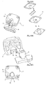
- Fig.5 - is a perspective view of a cylinder head and a muffler head.
- Fig.6 - is a bottom perspective view of a cylinder head and a muffler head.
- Fig.7 - is a top view of a cylinder head and a muffler head.
- Fig.8 - is a top perspective view of a cylinder head and a muffler head.
- Fig.9 - is a bottom perspective view of a cylinder head and a muffler head, in another embodiment of the present invention.
- Fig. 10 - is a top perspective view of a cylinder head and a muffler head, in another embodiment of the present invention.
- Fig. 11 - is a top view of a cylinder head and a muffler head, in another embodiment of the present invention.
- the circulation of the refrigerant used to realize the cooling is achieved by means of a hermetic piston compressor (1).
- the compressor (1) comprises a cylinder (2) which provides the pumping of the refrigerant in it, a cylinder head (3), located above the cylinder (2), whereby the refrigerant that is sucked and discharged is circulated, a valve plate (5) between the cylinder (2) and cylinder head (3), above which the cylinder head (3) is placed, a suction muffler (4) with insulating properties, placed onto the cylinder head (3), and preferably made of plastic material, wherein acoustical energy of the refrigerant circulated inside it, is reduced thereby minimizing the noise generated during the circulation and, which ensures that the refrigerant reaches the cylinder head (3) without being heated.
- the suction muffler (4) comprises a muffler head (8) whereby it is attached to the cylinder head (3) and, an outlet opening (6) on the muffler head (8) permitting the refrigerant to pass to the cylinder (2) therethrough.
- the cylinder head (3) comprises a muffler head housing (7) into which the muffler head (8) fits, an exhaust volume (9) wherein the refrigerant discharged from the cylinder (2) is circulated and, a bridge (12) whereby the upper edges of the muffler head housing (7) are connected together and, the muffler head (8) is fixed inside the muffler head housing (7).
- the muffler head (8) and the muffler head housing (7) incorporate one or more extensions (10) used to connect to each other and, one or more recesses (11) where the extension (10) is fitted.
- the muffler head (8) and the muffler head housing (7) are in contact with each other only at the mentioned extension (10) and recess (11) and between them, there is provided a gap (B) functioning as an insulator, whereby it is achieved that the heat transfer is reduced by minimizing the contact of the muffler head housing (7) with the hot portions of the cylinder head (3) and, that the refrigerant is prevented from being heated.
- the recess (11) is positioned on the muffler head (8) whereas the extension (10) that is used to fix the muffler head (8) by fitting it into the said recesses (11) is positioned on the muffler head housing (7).
- the extension (10) is positioned on the muffler head (8) whereas the recess (11) where the extension (10) is fitted into is positioned on the muffler head housing (7).
- At least one extension (10) in the form of a pin is positioned on the bridge (12) whereas recesses (11) in a form and amount appropriate with the said extensions (10) are positioned on the muffler head (8) (Fig.6, Fig.7, Fig.8).
- the extensions (10) in the form of a triangle prism, positioned at the both lateral surfaces of the muffler head housing (7), are fitted into the recesses (11) positioned at the lateral surfaces of the muffler head (8), which are suitable for the extensions (10) from the aspects of form, position and number.
- the muffler head (8) and the muffler head housing (7) are located so that up and down motion is prevented as a result of the triangle prism forms of the extensions (10) and recesses (11), and are fastened to the valve plate (5) wherein their front and back motion is prevented by means of the bridge (12) placed on the said extensions (10) and, except for the extensions (10) and the recesses (11), a gap (B) reducing the heat transfer is left in between (Fig.9, Fig. 10, Fig. 11).
- the muffler head housing (7) comprising an extension (10) with projections in different directions which are utilized to prevent motion in different directions, is placed on the muffler head (8) comprising an recess (11) suitable for the said extension (10) from the aspects of form and position and, is fastened to the valve plate (5) by means of screws wherein between the mentioned muffler head housing (7) and the muffler head (8), except for the extensions (10) and the recesses (11), a gap (B) reducing the heat transfer is left (Fig.5).
- the contact surface of the muffler head housing (7) and the muffler head (8) is reduced, resulting in that the refrigerant is taken into the cylinder cooler and thus denser and thereby, it is achieved that the performance of the compressor (1) is increased.
Landscapes
- Engineering & Computer Science (AREA)
- Mechanical Engineering (AREA)
- General Engineering & Computer Science (AREA)
- Compressor (AREA)
Claims (7)
- Verdichter (1), umfassend:einen Zylinder (2), der vorsieht, dass das Kühlmittel in ihm gepumpt wird; einen Saugleitungsdämpfer (4), durch den akustische Energie des darin zirkulierenden Kühlmittels reduziert wird, wodurch das Geräusch minimiert wird, das während der Zirkulation erzeugt wird, und der sicherstellt, dass das Kühlmittel den Zylinder (2) erreicht, ohne erwärmt zu werden; einen Dämpferkopf (8), durch den der Saugleitungsdämpfer (4) an einem Zylinderkopf (3) angebracht ist, und ein Dämpferkopfgehäuse (7), in das der Dämpferkopf (8) eingepasst ist; und dadurch gekennzeichnet, dass der Dämpferkopf (8) und das Dämpferkopfgehäuse (7) eine oder mehrere Verlängerungen (10) und eine oder mehrere Vertiefungen (11) umfassen, die benutzt werden, um sie miteinander zu verbinden, wobei sie nur an den Verlängerungen (10) und Vertiefungen (11) miteinander in Kontakt stehen, und wobei ein Anstieg der Temperatur des Kühlmittels verhindert wird, indem die Wärmeübertragung mit Hilfe eines Spalts (B) reduziert wird, der zwischen dem Dämpferkopf und dem Dämpferkopfgehäuse vorgesehen ist und als Isolation dient.
- Verdichter (1) nach Anspruch 1, dadurch gekennzeichnet, dass der Zylinderkopf (3) eine Brücke (12) umfasst, durch die die Kanten des Dämpferkopfgehäuses (7) durch die Erstreckung der Brücke (12) von den oberen Kanten des Dämpferkopfgehäuses (7) in das Innere des Dämpferkopfgehäuses verbunden sind, und die zu einer Befestigung im Dämpferkopfgehäuse (7) beiträgt.
- Verdichter nach Anspruch 1 und 2, dadurch gekennzeichnet, dass der Dämpferkopf (8) eine Vertiefung (11) umfasst, und dass ein Dämpferkopfgehäuse (7) eine Verlängerung (10) umfasst, die benutzt wird, um sie durch Einpassen in die Vertiefung (11) zu befestigen.
- Verdichter nach Anspruch 1 und 2, dadurch gekennzeichnet, dass der Dämpferkopf (8) eine Verlängerung (10) umfasst, und dass ein Dämpferkopfgehäuse (7) eine Vertiefung (11) umfasst, in die die Verlängerung (10) einpassbar ist.
- Verdichter nach den Ansprüchen 1 bis 4, dadurch gekennzeichnet, dass der Dämpferkopf (8) und ein Dämpferkopfgehäuse (7) eine zylinderförmige Verlängerung (10) und eine zylinderförmige Vertiefung (11) aufweisen, in die die Verlängerung (10) einpassbar ist.
- Verdichter nach den Ansprüchen 1 bis 4, dadurch gekennzeichnet, dass der Dämpferkopf (8) und ein Dämpferkopfgehäuse (7) eine Verlängerung in der Form eines Dreiecksprismas und eine Vertiefung (11) in der Form eines Dreiecksprismas umfassen, in die die Verlängerung (10) einpassbar ist.
- Verdichter nach den Ansprüchen 1 bis 4, dadurch gekennzeichnet, dass der Dämpferkopf (8) und ein Dämpferkopfgehäuse (7) eine Verlängerung (10) in einer Form und Position umfassen, die eine Bewegung in unterschiedliche Richtungen verhindert, und eine Vertiefung (11) in einer Form und Position, die für die Verlängerung (10) geeignet ist, und in die die Verlängerung (10) einpassbar ist.
Applications Claiming Priority (2)
| Application Number | Priority Date | Filing Date | Title |
|---|---|---|---|
| TR200400607 | 2004-03-26 | ||
| PCT/IB2005/051032 WO2005093255A1 (en) | 2004-03-26 | 2005-03-25 | Compressor with suction muffler |
Publications (2)
| Publication Number | Publication Date |
|---|---|
| EP1740832A1 EP1740832A1 (de) | 2007-01-10 |
| EP1740832B1 true EP1740832B1 (de) | 2007-06-06 |
Family
ID=34962045
Family Applications (1)
| Application Number | Title | Priority Date | Filing Date |
|---|---|---|---|
| EP05718563A Expired - Lifetime EP1740832B1 (de) | 2004-03-26 | 2005-03-25 | Verdichter mit saugschalldämpfer |
Country Status (6)
| Country | Link |
|---|---|
| EP (1) | EP1740832B1 (de) |
| AT (1) | ATE364135T1 (de) |
| DE (1) | DE602005001324T2 (de) |
| ES (1) | ES2286804T3 (de) |
| TR (1) | TR200605252T1 (de) |
| WO (1) | WO2005093255A1 (de) |
Cited By (1)
| Publication number | Priority date | Publication date | Assignee | Title |
|---|---|---|---|---|
| WO2013091047A1 (en) * | 2011-12-20 | 2013-06-27 | Whirlpool S.A. | Cylinder cover for alternative compressor |
Families Citing this family (4)
| Publication number | Priority date | Publication date | Assignee | Title |
|---|---|---|---|---|
| RU2549005C2 (ru) * | 2013-02-06 | 2015-04-20 | Закрытое акционерное общество "АТЛАНТ" | Клапанно-поршневой узел герметичного холодильного компрессора |
| WO2016139267A1 (en) | 2015-03-04 | 2016-09-09 | Arcelik Anonim Sirketi | A compressor comprising a suction muffler |
| TR201711734A2 (tr) * | 2017-08-09 | 2019-02-21 | Arcelik As | Si̇li̇ndi̇r kafasi i̇le si̇li̇ndi̇r deli̇ği̇ arasinda etki̇n sizdirmazlik sağlanan bi̇r kompresör |
| US12066016B2 (en) * | 2019-07-12 | 2024-08-20 | Nidec Global Appliance Brasil Ltda | Reciprocating compressor having a suction acoustic filter with a fastener that deforms when in place |
Family Cites Families (6)
| Publication number | Priority date | Publication date | Assignee | Title |
|---|---|---|---|---|
| JPS58160570A (ja) * | 1982-03-18 | 1983-09-24 | Matsushita Refrig Co | 冷媒圧縮機の消音装置 |
| CA1210741A (en) * | 1981-08-25 | 1986-09-02 | Hideki Kawai | Sealed type motor compressor |
| IT1184167B (it) * | 1985-03-21 | 1987-10-22 | Eurodomestici Ind Riunite | Perfezionamento nei motocompressori sigillati per circuiti frigoriferi |
| KR0136621Y1 (ko) * | 1995-10-31 | 1999-03-20 | 구자홍 | 밀폐형 전동 압축기의 흡입소음기 체결구조 |
| KR0186169B1 (ko) * | 1995-11-15 | 1999-05-01 | 구자홍 | 밀폐형 압축기의 소음기체결장치 |
| DE19923734C2 (de) * | 1999-05-22 | 2001-03-29 | Danfoss Compressors Gmbh | Saugschalldämpfer für einen hermetisch gekapselten Verdichter |
-
2005
- 2005-03-25 TR TR2006/05252T patent/TR200605252T1/xx unknown
- 2005-03-25 AT AT05718563T patent/ATE364135T1/de not_active IP Right Cessation
- 2005-03-25 EP EP05718563A patent/EP1740832B1/de not_active Expired - Lifetime
- 2005-03-25 DE DE602005001324T patent/DE602005001324T2/de not_active Expired - Lifetime
- 2005-03-25 ES ES05718563T patent/ES2286804T3/es not_active Expired - Lifetime
- 2005-03-25 WO PCT/IB2005/051032 patent/WO2005093255A1/en not_active Ceased
Cited By (2)
| Publication number | Priority date | Publication date | Assignee | Title |
|---|---|---|---|---|
| WO2013091047A1 (en) * | 2011-12-20 | 2013-06-27 | Whirlpool S.A. | Cylinder cover for alternative compressor |
| US11162485B2 (en) | 2011-12-20 | 2021-11-02 | Embraco—Indústria De Compressores E Soluções Em Refrigeração Ltda. | Cylinder cover for alternative compressor |
Also Published As
| Publication number | Publication date |
|---|---|
| ES2286804T3 (es) | 2007-12-01 |
| WO2005093255A1 (en) | 2005-10-06 |
| EP1740832A1 (de) | 2007-01-10 |
| DE602005001324D1 (de) | 2007-07-19 |
| TR200605252T1 (tr) | 2007-01-22 |
| ATE364135T1 (de) | 2007-06-15 |
| DE602005001324T2 (de) | 2008-02-07 |
Similar Documents
| Publication | Publication Date | Title |
|---|---|---|
| US8257061B2 (en) | Hermetic compressor with internal thermal insulation | |
| KR0143182B1 (ko) | 압축기 | |
| CA2069208C (en) | Refrigeration compressor having a contoured piston | |
| CN104603461B (zh) | 密闭型压缩机和制冷装置 | |
| WO2000026536A1 (en) | Opening and closing system for oil path of linear compressor | |
| EP1740832B1 (de) | Verdichter mit saugschalldämpfer | |
| US6547536B2 (en) | Reciprocating compressor having a discharge pulsation | |
| EP2433006A1 (de) | Kompressor mit einem zylinderkopf | |
| EP1718869B1 (de) | Kältekompressor | |
| WO2017194516A1 (en) | A hermetic compressor with improved sealing | |
| EP1957796B1 (de) | Verdichter | |
| WO2017211704A1 (en) | A hermetic compressor comprising an elastic suction muffler | |
| WO2006038146A1 (en) | A compressor | |
| WO2016139267A1 (en) | A compressor comprising a suction muffler | |
| EP1771660A1 (de) | Verdichter | |
| JP2848418B2 (ja) | 密閉型電動圧縮機 | |
| JPH0599141A (ja) | 密閉型電動圧縮機 | |
| WO2019091665A1 (en) | A hermetic compressor with improved sealing | |
| CN113623226A (zh) | 轴承组件、压缩机及制冷装置 | |
| JPH03290073A (ja) | 密閉型電動圧縮機 | |
| WO2007017820A1 (en) | A compressor | |
| WO2009132955A1 (en) | A compressor | |
| WO2006092771A1 (en) | A compressor | |
| KR20030059747A (ko) | 압축기의 흡입 머플러 | |
| MX2008007838A (en) | Hermetic compressor with internal thermal insulation |
Legal Events
| Date | Code | Title | Description |
|---|---|---|---|
| PUAI | Public reference made under article 153(3) epc to a published international application that has entered the european phase |
Free format text: ORIGINAL CODE: 0009012 |
|
| 17P | Request for examination filed |
Effective date: 20060928 |
|
| AK | Designated contracting states |
Kind code of ref document: A1 Designated state(s): AT BE BG CH CY CZ DE DK EE ES FI FR GB GR HU IE IS IT LI LT LU MC NL PL PT RO SE SI SK TR |
|
| GRAP | Despatch of communication of intention to grant a patent |
Free format text: ORIGINAL CODE: EPIDOSNIGR1 |
|
| GRAS | Grant fee paid |
Free format text: ORIGINAL CODE: EPIDOSNIGR3 |
|
| GRAA | (expected) grant |
Free format text: ORIGINAL CODE: 0009210 |
|
| AK | Designated contracting states |
Kind code of ref document: B1 Designated state(s): AT BE BG CH CY CZ DE DK EE ES FI FR GB GR HU IE IS IT LI LT LU MC NL PL PT RO SE SI SK TR |
|
| DAX | Request for extension of the european patent (deleted) | ||
| PG25 | Lapsed in a contracting state [announced via postgrant information from national office to epo] |
Ref country code: LI Free format text: LAPSE BECAUSE OF FAILURE TO SUBMIT A TRANSLATION OF THE DESCRIPTION OR TO PAY THE FEE WITHIN THE PRESCRIBED TIME-LIMIT Effective date: 20070606 Ref country code: CH Free format text: LAPSE BECAUSE OF FAILURE TO SUBMIT A TRANSLATION OF THE DESCRIPTION OR TO PAY THE FEE WITHIN THE PRESCRIBED TIME-LIMIT Effective date: 20070606 Ref country code: FI Free format text: LAPSE BECAUSE OF FAILURE TO SUBMIT A TRANSLATION OF THE DESCRIPTION OR TO PAY THE FEE WITHIN THE PRESCRIBED TIME-LIMIT Effective date: 20070606 |
|
| REG | Reference to a national code |
Ref country code: GB Ref legal event code: FG4D |
|
| REG | Reference to a national code |
Ref country code: CH Ref legal event code: EP |
|
| REG | Reference to a national code |
Ref country code: IE Ref legal event code: FG4D |
|
| REF | Corresponds to: |
Ref document number: 602005001324 Country of ref document: DE Date of ref document: 20070719 Kind code of ref document: P |
|
| PG25 | Lapsed in a contracting state [announced via postgrant information from national office to epo] |
Ref country code: SE Free format text: LAPSE BECAUSE OF FAILURE TO SUBMIT A TRANSLATION OF THE DESCRIPTION OR TO PAY THE FEE WITHIN THE PRESCRIBED TIME-LIMIT Effective date: 20070906 |
|
| ET | Fr: translation filed | ||
| PG25 | Lapsed in a contracting state [announced via postgrant information from national office to epo] |
Ref country code: AT Free format text: LAPSE BECAUSE OF FAILURE TO SUBMIT A TRANSLATION OF THE DESCRIPTION OR TO PAY THE FEE WITHIN THE PRESCRIBED TIME-LIMIT Effective date: 20070606 Ref country code: PL Free format text: LAPSE BECAUSE OF FAILURE TO SUBMIT A TRANSLATION OF THE DESCRIPTION OR TO PAY THE FEE WITHIN THE PRESCRIBED TIME-LIMIT Effective date: 20070606 |
|
| REG | Reference to a national code |
Ref country code: ES Ref legal event code: FG2A Ref document number: 2286804 Country of ref document: ES Kind code of ref document: T3 |
|
| NLV1 | Nl: lapsed or annulled due to failure to fulfill the requirements of art. 29p and 29m of the patents act | ||
| REG | Reference to a national code |
Ref country code: CH Ref legal event code: PL |
|
| PG25 | Lapsed in a contracting state [announced via postgrant information from national office to epo] |
Ref country code: BE Free format text: LAPSE BECAUSE OF FAILURE TO SUBMIT A TRANSLATION OF THE DESCRIPTION OR TO PAY THE FEE WITHIN THE PRESCRIBED TIME-LIMIT Effective date: 20070606 |
|
| PG25 | Lapsed in a contracting state [announced via postgrant information from national office to epo] |
Ref country code: SI Free format text: LAPSE BECAUSE OF FAILURE TO SUBMIT A TRANSLATION OF THE DESCRIPTION OR TO PAY THE FEE WITHIN THE PRESCRIBED TIME-LIMIT Effective date: 20070606 Ref country code: NL Free format text: LAPSE BECAUSE OF FAILURE TO SUBMIT A TRANSLATION OF THE DESCRIPTION OR TO PAY THE FEE WITHIN THE PRESCRIBED TIME-LIMIT Effective date: 20070606 Ref country code: IS Free format text: LAPSE BECAUSE OF FAILURE TO SUBMIT A TRANSLATION OF THE DESCRIPTION OR TO PAY THE FEE WITHIN THE PRESCRIBED TIME-LIMIT Effective date: 20071006 Ref country code: CZ Free format text: LAPSE BECAUSE OF FAILURE TO SUBMIT A TRANSLATION OF THE DESCRIPTION OR TO PAY THE FEE WITHIN THE PRESCRIBED TIME-LIMIT Effective date: 20070606 Ref country code: PT Free format text: LAPSE BECAUSE OF FAILURE TO SUBMIT A TRANSLATION OF THE DESCRIPTION OR TO PAY THE FEE WITHIN THE PRESCRIBED TIME-LIMIT Effective date: 20071106 |
|
| PG25 | Lapsed in a contracting state [announced via postgrant information from national office to epo] |
Ref country code: LT Free format text: LAPSE BECAUSE OF FAILURE TO SUBMIT A TRANSLATION OF THE DESCRIPTION OR TO PAY THE FEE WITHIN THE PRESCRIBED TIME-LIMIT Effective date: 20070606 |
|
| PLBE | No opposition filed within time limit |
Free format text: ORIGINAL CODE: 0009261 |
|
| STAA | Information on the status of an ep patent application or granted ep patent |
Free format text: STATUS: NO OPPOSITION FILED WITHIN TIME LIMIT |
|
| PG25 | Lapsed in a contracting state [announced via postgrant information from national office to epo] |
Ref country code: GR Free format text: LAPSE BECAUSE OF FAILURE TO SUBMIT A TRANSLATION OF THE DESCRIPTION OR TO PAY THE FEE WITHIN THE PRESCRIBED TIME-LIMIT Effective date: 20070907 Ref country code: DK Free format text: LAPSE BECAUSE OF FAILURE TO SUBMIT A TRANSLATION OF THE DESCRIPTION OR TO PAY THE FEE WITHIN THE PRESCRIBED TIME-LIMIT Effective date: 20070606 |
|
| 26N | No opposition filed |
Effective date: 20080307 |
|
| PG25 | Lapsed in a contracting state [announced via postgrant information from national office to epo] |
Ref country code: RO Free format text: LAPSE BECAUSE OF FAILURE TO SUBMIT A TRANSLATION OF THE DESCRIPTION OR TO PAY THE FEE WITHIN THE PRESCRIBED TIME-LIMIT Effective date: 20070606 |
|
| PG25 | Lapsed in a contracting state [announced via postgrant information from national office to epo] |
Ref country code: MC Free format text: LAPSE BECAUSE OF NON-PAYMENT OF DUE FEES Effective date: 20080331 |
|
| PG25 | Lapsed in a contracting state [announced via postgrant information from national office to epo] |
Ref country code: EE Free format text: LAPSE BECAUSE OF FAILURE TO SUBMIT A TRANSLATION OF THE DESCRIPTION OR TO PAY THE FEE WITHIN THE PRESCRIBED TIME-LIMIT Effective date: 20070606 Ref country code: IE Free format text: LAPSE BECAUSE OF NON-PAYMENT OF DUE FEES Effective date: 20080325 |
|
| PG25 | Lapsed in a contracting state [announced via postgrant information from national office to epo] |
Ref country code: CY Free format text: LAPSE BECAUSE OF FAILURE TO SUBMIT A TRANSLATION OF THE DESCRIPTION OR TO PAY THE FEE WITHIN THE PRESCRIBED TIME-LIMIT Effective date: 20070606 |
|
| PG25 | Lapsed in a contracting state [announced via postgrant information from national office to epo] |
Ref country code: BG Free format text: LAPSE BECAUSE OF FAILURE TO SUBMIT A TRANSLATION OF THE DESCRIPTION OR TO PAY THE FEE WITHIN THE PRESCRIBED TIME-LIMIT Effective date: 20070906 |
|
| PG25 | Lapsed in a contracting state [announced via postgrant information from national office to epo] |
Ref country code: LU Free format text: LAPSE BECAUSE OF NON-PAYMENT OF DUE FEES Effective date: 20080325 Ref country code: HU Free format text: LAPSE BECAUSE OF FAILURE TO SUBMIT A TRANSLATION OF THE DESCRIPTION OR TO PAY THE FEE WITHIN THE PRESCRIBED TIME-LIMIT Effective date: 20071207 |
|
| REG | Reference to a national code |
Ref country code: FR Ref legal event code: PLFP Year of fee payment: 12 |
|
| REG | Reference to a national code |
Ref country code: FR Ref legal event code: PLFP Year of fee payment: 13 |
|
| REG | Reference to a national code |
Ref country code: FR Ref legal event code: PLFP Year of fee payment: 14 |
|
| P01 | Opt-out of the competence of the unified patent court (upc) registered |
Effective date: 20230523 |
|
| PGFP | Annual fee paid to national office [announced via postgrant information from national office to epo] |
Ref country code: DE Payment date: 20240320 Year of fee payment: 20 Ref country code: GB Payment date: 20240320 Year of fee payment: 20 Ref country code: SK Payment date: 20240318 Year of fee payment: 20 |
|
| PGFP | Annual fee paid to national office [announced via postgrant information from national office to epo] |
Ref country code: TR Payment date: 20240304 Year of fee payment: 20 Ref country code: IT Payment date: 20240329 Year of fee payment: 20 Ref country code: FR Payment date: 20240321 Year of fee payment: 20 |
|
| PGFP | Annual fee paid to national office [announced via postgrant information from national office to epo] |
Ref country code: ES Payment date: 20240426 Year of fee payment: 20 |
|
| REG | Reference to a national code |
Ref country code: DE Ref legal event code: R071 Ref document number: 602005001324 Country of ref document: DE |
|
| REG | Reference to a national code |
Ref country code: ES Ref legal event code: FD2A Effective date: 20250401 |
|
| REG | Reference to a national code |
Ref country code: SK Ref legal event code: MK4A Ref document number: E 2527 Country of ref document: SK Expiry date: 20250325 |
|
| REG | Reference to a national code |
Ref country code: GB Ref legal event code: PE20 Expiry date: 20250324 |
|
| PG25 | Lapsed in a contracting state [announced via postgrant information from national office to epo] |
Ref country code: ES Free format text: LAPSE BECAUSE OF EXPIRATION OF PROTECTION Effective date: 20250326 |
|
| PG25 | Lapsed in a contracting state [announced via postgrant information from national office to epo] |
Ref country code: GB Free format text: LAPSE BECAUSE OF EXPIRATION OF PROTECTION Effective date: 20250324 Ref country code: SK Free format text: LAPSE BECAUSE OF EXPIRATION OF PROTECTION Effective date: 20250325 |