EP1740834B1 - Dispositif de distribution de gaz - Google Patents
Dispositif de distribution de gaz Download PDFInfo
- Publication number
- EP1740834B1 EP1740834B1 EP05737487A EP05737487A EP1740834B1 EP 1740834 B1 EP1740834 B1 EP 1740834B1 EP 05737487 A EP05737487 A EP 05737487A EP 05737487 A EP05737487 A EP 05737487A EP 1740834 B1 EP1740834 B1 EP 1740834B1
- Authority
- EP
- European Patent Office
- Prior art keywords
- distribution tube
- outside diameter
- branch
- tube
- compressors
- Prior art date
- Legal status (The legal status is an assumption and is not a legal conclusion. Google has not performed a legal analysis and makes no representation as to the accuracy of the status listed.)
- Ceased
Links
Images

Classifications
-
- F—MECHANICAL ENGINEERING; LIGHTING; HEATING; WEAPONS; BLASTING
- F25—REFRIGERATION OR COOLING; COMBINED HEATING AND REFRIGERATION SYSTEMS; HEAT PUMP SYSTEMS; MANUFACTURE OR STORAGE OF ICE; LIQUEFACTION SOLIDIFICATION OF GASES
- F25B—REFRIGERATION MACHINES, PLANTS OR SYSTEMS; COMBINED HEATING AND REFRIGERATION SYSTEMS; HEAT PUMP SYSTEMS
- F25B31/00—Compressor arrangements
- F25B31/002—Lubrication
-
- F—MECHANICAL ENGINEERING; LIGHTING; HEATING; WEAPONS; BLASTING
- F04—POSITIVE - DISPLACEMENT MACHINES FOR LIQUIDS; PUMPS FOR LIQUIDS OR ELASTIC FLUIDS
- F04C—ROTARY-PISTON, OR OSCILLATING-PISTON, POSITIVE-DISPLACEMENT MACHINES FOR LIQUIDS; ROTARY-PISTON, OR OSCILLATING-PISTON, POSITIVE-DISPLACEMENT PUMPS
- F04C23/00—Combinations of two or more pumps, each being of rotary-piston or oscillating-piston type, specially adapted for elastic fluids; Pumping installations specially adapted for elastic fluids; Multi-stage pumps specially adapted for elastic fluids
- F04C23/001—Combinations of two or more pumps, each being of rotary-piston or oscillating-piston type, specially adapted for elastic fluids; Pumping installations specially adapted for elastic fluids; Multi-stage pumps specially adapted for elastic fluids of similar working principle
-
- F—MECHANICAL ENGINEERING; LIGHTING; HEATING; WEAPONS; BLASTING
- F04—POSITIVE - DISPLACEMENT MACHINES FOR LIQUIDS; PUMPS FOR LIQUIDS OR ELASTIC FLUIDS
- F04C—ROTARY-PISTON, OR OSCILLATING-PISTON, POSITIVE-DISPLACEMENT MACHINES FOR LIQUIDS; ROTARY-PISTON, OR OSCILLATING-PISTON, POSITIVE-DISPLACEMENT PUMPS
- F04C23/00—Combinations of two or more pumps, each being of rotary-piston or oscillating-piston type, specially adapted for elastic fluids; Pumping installations specially adapted for elastic fluids; Multi-stage pumps specially adapted for elastic fluids
- F04C23/008—Hermetic pumps
-
- F—MECHANICAL ENGINEERING; LIGHTING; HEATING; WEAPONS; BLASTING
- F04—POSITIVE - DISPLACEMENT MACHINES FOR LIQUIDS; PUMPS FOR LIQUIDS OR ELASTIC FLUIDS
- F04C—ROTARY-PISTON, OR OSCILLATING-PISTON, POSITIVE-DISPLACEMENT MACHINES FOR LIQUIDS; ROTARY-PISTON, OR OSCILLATING-PISTON, POSITIVE-DISPLACEMENT PUMPS
- F04C29/00—Component parts, details or accessories of pumps or pumping installations, not provided for in groups F04C18/00 - F04C28/00
- F04C29/02—Lubrication; Lubricant separation
-
- F—MECHANICAL ENGINEERING; LIGHTING; HEATING; WEAPONS; BLASTING
- F25—REFRIGERATION OR COOLING; COMBINED HEATING AND REFRIGERATION SYSTEMS; HEAT PUMP SYSTEMS; MANUFACTURE OR STORAGE OF ICE; LIQUEFACTION SOLIDIFICATION OF GASES
- F25B—REFRIGERATION MACHINES, PLANTS OR SYSTEMS; COMBINED HEATING AND REFRIGERATION SYSTEMS; HEAT PUMP SYSTEMS
- F25B41/00—Fluid-circulation arrangements
- F25B41/40—Fluid line arrangements
-
- F—MECHANICAL ENGINEERING; LIGHTING; HEATING; WEAPONS; BLASTING
- F04—POSITIVE - DISPLACEMENT MACHINES FOR LIQUIDS; PUMPS FOR LIQUIDS OR ELASTIC FLUIDS
- F04C—ROTARY-PISTON, OR OSCILLATING-PISTON, POSITIVE-DISPLACEMENT MACHINES FOR LIQUIDS; ROTARY-PISTON, OR OSCILLATING-PISTON, POSITIVE-DISPLACEMENT PUMPS
- F04C18/00—Rotary-piston pumps specially adapted for elastic fluids
- F04C18/02—Rotary-piston pumps specially adapted for elastic fluids of arcuate-engagement type, i.e. with circular translatory movement of co-operating members, each member having the same number of teeth or tooth-equivalents
- F04C18/0207—Rotary-piston pumps specially adapted for elastic fluids of arcuate-engagement type, i.e. with circular translatory movement of co-operating members, each member having the same number of teeth or tooth-equivalents both members having co-operating elements in spiral form
- F04C18/0215—Rotary-piston pumps specially adapted for elastic fluids of arcuate-engagement type, i.e. with circular translatory movement of co-operating members, each member having the same number of teeth or tooth-equivalents both members having co-operating elements in spiral form where only one member is moving
-
- F—MECHANICAL ENGINEERING; LIGHTING; HEATING; WEAPONS; BLASTING
- F04—POSITIVE - DISPLACEMENT MACHINES FOR LIQUIDS; PUMPS FOR LIQUIDS OR ELASTIC FLUIDS
- F04C—ROTARY-PISTON, OR OSCILLATING-PISTON, POSITIVE-DISPLACEMENT MACHINES FOR LIQUIDS; ROTARY-PISTON, OR OSCILLATING-PISTON, POSITIVE-DISPLACEMENT PUMPS
- F04C18/00—Rotary-piston pumps specially adapted for elastic fluids
- F04C18/08—Rotary-piston pumps specially adapted for elastic fluids of intermeshing-engagement type, i.e. with engagement of co-operating members similar to that of toothed gearing
- F04C18/12—Rotary-piston pumps specially adapted for elastic fluids of intermeshing-engagement type, i.e. with engagement of co-operating members similar to that of toothed gearing of other than internal-axis type
- F04C18/14—Rotary-piston pumps specially adapted for elastic fluids of intermeshing-engagement type, i.e. with engagement of co-operating members similar to that of toothed gearing of other than internal-axis type with toothed rotary pistons
- F04C18/16—Rotary-piston pumps specially adapted for elastic fluids of intermeshing-engagement type, i.e. with engagement of co-operating members similar to that of toothed gearing of other than internal-axis type with toothed rotary pistons with helical teeth, e.g. chevron-shaped, screw type
-
- F—MECHANICAL ENGINEERING; LIGHTING; HEATING; WEAPONS; BLASTING
- F04—POSITIVE - DISPLACEMENT MACHINES FOR LIQUIDS; PUMPS FOR LIQUIDS OR ELASTIC FLUIDS
- F04C—ROTARY-PISTON, OR OSCILLATING-PISTON, POSITIVE-DISPLACEMENT MACHINES FOR LIQUIDS; ROTARY-PISTON, OR OSCILLATING-PISTON, POSITIVE-DISPLACEMENT PUMPS
- F04C2240/00—Components
- F04C2240/80—Other components
- F04C2240/806—Pipes for fluids; Fittings therefor
-
- F—MECHANICAL ENGINEERING; LIGHTING; HEATING; WEAPONS; BLASTING
- F25—REFRIGERATION OR COOLING; COMBINED HEATING AND REFRIGERATION SYSTEMS; HEAT PUMP SYSTEMS; MANUFACTURE OR STORAGE OF ICE; LIQUEFACTION SOLIDIFICATION OF GASES
- F25B—REFRIGERATION MACHINES, PLANTS OR SYSTEMS; COMBINED HEATING AND REFRIGERATION SYSTEMS; HEAT PUMP SYSTEMS
- F25B2400/00—Component parts or details not otherwise provided for in this subclass
- F25B2400/07—Details of compressors or related parts
- F25B2400/075—Details of compressors or related parts with parallel compressors
Definitions
- the present invention relates to a suction gas distribution device for parallel compressor installations.
- Compressors are often arranged in parallel in refrigeration applications. Oil apportioning systems in this case are complex and expensive, based on combining common oil collectors, devices for measuring individual levels, and solenoid distribution valves. These systems are prohibitively expensive in air-conditioning applications.
- Another, less expensive, method consists of forcing the oil return to a compressor and then creating pressure drops at the inlet of each to the compressor to force a balanced oil distribution.
- the disadvantage of this system resides in the pressure losses generated, which have a direct impact on the energy performance of the cooling system.
- producing several welds to create local pressure losses impacts cost as well as reliability, as the welds increase the risk of leakage.
- U.S. Patent No. 3,386,262 describes a Y connector and separate flow restriction in a branch line.
- U.S. Patent No. 4,729,228 describes a gas flow separator.
- U.S. Patent No. 4,411,141 also shows an oil separation device inside the suction line, and a nonreturn valve in the oil equalization line.
- U.S. Patent No. 4,741,674 and U.S. Patent No. 4,750,337 relate to parallel compressor arrangements where the suction pressure in the compressor body is kept equal.
- U.S. Patent No. 4,741,674 describes a separate pressure equalization line, different from the oil level equalization line. Valves responding to pressure drops for each compressor are present in the suction distributor to eliminate suction at the inoperative compressors.
- U.S. Patent No. 4,750,337 describes a valve arrangement in the suction distributor that ensures pressure equalization in the compressor body.
- U.S. Patent No. 4,551,989 describes a suction distributor arrangement using a T part with a distribution tube mounted below the suction orifices of the compressor bodies, with branch lines connecting the distribution tube to the compressor body and extending perpendicularly to the distribution tube.
- the dimensions of the branches are designed to allow a sufficient gas velocity for the oil return to the compressor bodies.
- EP 1 139 038 discloses a parallel compressor installation according to the preamble of claim 1.
- the present invention overcomes the disadvantages of the previous devices exhibiting overcomplexity or pressure losses in the oil suction or equalization lines by using a particular geometry to equalize the pressures in the oil pans of each compressor and thus use simple equalization lines.
- the present invention relates to a parallel compressor installation according to claim 1.
- the compressors may be of various kinds. They may be for example scroll compressors, piston compressors, rotary or screw compressors, or hermetic or semihermetic compressors.
- the present invention is also characterized in that the distribution tube has a straight portion upstream of the first branch, the length of said straight portion being equal to at least five times the outside diameter of the distribution tube.
- the length of the straight portion of the distribution tube upstream of the first branch is between five and seven times the outside diameter of the distribution tube. The presence of this straight portion leads to a homogenous velocity profile after the bend, if present, at the end of the distribution tube.
- the present invention according to one exemplary embodiment is also characterized in that the branch tubes have a smaller outside diameter than the outside diameter of the distribution tube.
- the ratio between the outside diameter of the branch tubes and the outside diameter of the distribution tube is between 60 and 85%.
- the outside diameter of the branch tubes is essentially equal to 41,27 mm (1-5/8 inches), the outside diameter of the distribution tube being essentially equal to 66,67 mm (2-5/8 inches) in the case that three or four compressors are arranged in parallel or essentially equal to 53,97 mm (2-1/8 inches) in the case that two compressors are arranged in parallel.
- the various diameters used are chosen to maintain the minimum gas velocity and guarantee equal pressure levels between the compressors.
- the present invention according to one exemplary embodiment is also characterized in that the distance between two branches of the distribution tube is at least five times the outside diameter of the distribution tube. The distance between the branches prevents perturbations in the velocity profile brought about by one branch from altering the gas behavior in the next branch.
- the present invention is also characterized in that the branch tubes have a bent portion downstream of the portion whose axis makes an angle of between 55° and 65° with the axis of the distribution tube, said bent portion having a bending angle of between 115 and 120° and a bending ratio essentially equal to 1.25 times the outside diameter of the branch tube. This bent portion contributes to equalization of the pressure between the compressors.
- the present invention is also characterized in that the last branch tube has a straight portion positioned in the axis of the distribution tube and communicating therewith, upstream of the straight portion whose axis forms an angle of between 55° and 65° with the axis of the distribution tube.
- the desired effect of supplying a gas at an equal pressure for all the compressors is based on using branch portions inclined at an angle of between 55° and 65° relative to the distribution flow.
- the inclined portions must be adjacent to the distribution tube or connected to the straight portion of the end branch which is in the extension of the distribution tube.
- the present invention is also characterized in that the straight portion of the last branch tube positioned in the axis of the distribution tube and communicating therewith has a length equal to at least five times the outside diameter of the distribution tube. This straight portion prevents perturbations in the velocity profile brought about by the penultimate branch from altering the gas behavior in the last branch.
- the present invention is also characterized in that at least one of the branch tubes has a collar at its end joined to the distribution tube.
- the collar attachment prevents welds from projecting into the flow, causing pressure losses and reducing the reliability of the device.
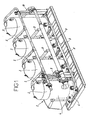
- Figure 1 is a general view of an arrangement of four compressors in parallel using the distribution device.
- Figure 2 is a view of the distribution device for four compressors in parallel.
- Figure 3 is a view of a branch tube showing a collar.
- Figure 4 is a view of the distribution device for two compressors in parallel.
- Figure 1 describes an arrangement of compressors in parallel, including:
- Figure 2 shows the distribution device 7 according to a first embodiment for an arrangement of four compressors.
- the distribution tube 8 has, upstream of the first branch 13, a straight portion 14 that is about 330 mm long and has five to seven times the outside diameter of the distribution tube 8.
- the outside diameter of the branch tubes 9 is essentially equal to 41,27 mm (1-5/8 inches), the outside diameter of the distribution tube 8 being essentially equal to 66,67 mm (2-5/8 inches).
- the distance between two branches of the distribution tube is greater than 7 times the outside diameter of the distribution tube. In the embodiment shown in Figure 2 , this distance is about 476 mm.
- the distribution device has four branch tubes: three lateral branch tubes 9 and a last end branch tube 10.
- the lateral branch tubes 9 are identical. They have the following adjacent portions between the distribution tube and the inlet orifice of a compressor:
- the last branch tube 10 has, between the distribution tube 8 and the straight portion 12 forming an angle of about 60° with the axis of the distribution tube 8, the following adjacent portions:
- the distribution tube 8 has a reduction in diameter 22 at is end communicating with the last branch tube 10. This reduction in diameter 22 reduces the outside diameter of the tube from about 66,67 mm (2-5/8 inches) to about 41,27 mm (1-5/8 inches).
- Figure 3 shows a lateral branch tube 9 having a collar 23 at its end joined to the distribution tube.
- Figure 4 shows an embodiment for placing two compressors in parallel.
- the outside diameter of the distribution tube is about 53,97 mm (2-1/8 inches). All the other measurements are the same as in the embodiment shown in Figure 2 , using only two branches: one lateral branch 9 and one end branch 10.
Landscapes
- Engineering & Computer Science (AREA)
- Mechanical Engineering (AREA)
- General Engineering & Computer Science (AREA)
- Physics & Mathematics (AREA)
- Thermal Sciences (AREA)
- Compressor (AREA)
- Compressors, Vaccum Pumps And Other Relevant Systems (AREA)
- Incineration Of Waste (AREA)
- Crystals, And After-Treatments Of Crystals (AREA)
- Separation By Low-Temperature Treatments (AREA)
- Gas Separation By Absorption (AREA)
- Treating Waste Gases (AREA)
Claims (11)
- Installation à compresseurs parallèles, comprenant :au moins deux compresseurs de réfrigération (2), chacun ayant un corps (3) délimitant un espace intérieur (4) ;au moins un tuyau d'égalisation de niveau d'huile (5) fournissant une communication entre des carters d'huile (6) prévus dans les corps (3) des compresseurs (2) ; etau moins un dispositif (7) pour distribuer un gaz d'aspiration, comprenant un tuyau de distribution essentiellement droit (8) ainsi qu'au moins deux tuyaux de branchement (9, 10) fournissant une communication entre le tuyau de distribution (8) au niveau des portions de branchement et des espaces (4) à l'intérieur des corps (3) des compresseurs,caractérisée en ce que lesdits au moins deux tuyaux de branchement (9, 10) comportent au moins une portion (12) formant un angle entre 55° et 65° avec l'axe du tuyau de distribution, la portion desdits au moins deux tuyaux de branchement (9, 10) formant un angle entre 55° et 65°, l'axe du tuyau de distribution (8) étant adjacent au tuyau de distribution (8) sur au moins l'un desdits au moins deux tuyaux de branchement (9).
- Installation à compresseurs parallèles selon la revendication 1, caractérisée en ce que le tuyau de distribution (8) comporte une portion droite (14) en amont d'une première portion de branchement (13), la longueur de ladite portion droite étant égale à au moins cinq fois le diamètre extérieur du tuyau de distribution (8).
- Installation à compresseurs parallèles selon la revendication 2, caractérisée en ce que la longueur de la portion droite (14) du tuyau de distribution (8) en amont de la première portion de branchement (13) est entre cinq et sept fois le diamètre extérieur du tuyau de distribution (8).
- Installation à compresseurs parallèles selon la revendication 1, caractérisée en ce que lesdits au moins deux tuyaux de branchement (9, 10) ont un diamètre extérieur plus petit que le diamètre extérieur du tuyau de distribution (8).
- Installation à compresseurs parallèles selon la revendication 1, caractérisée en ce que le rapport entre le diamètre extérieur desdits au moins deux tuyaux de branchement (9, 10) et le diamètre extérieur du tuyau de distribution (8) se situe entre 60 et 85 %.
- Installation à compresseurs parallèles selon la revendication 1, caractérisée en ce que le diamètre extérieur desdits au moins deux tuyaux de branchement (9, 10) est essentiellement égal à 41,27 mm (1-5/8 pouces), le diamètre extérieur du tuyau de distribution (8) étant essentiellement égal à 66,67 mm (2-5/8 pouces) dans le cas où trois ou quatre compresseurs (2) fonctionnent en parallèle, ou étant essentiellement égal à 53,97 mm (2-1/8 pouces) dans le cas où deux compresseurs fonctionnent en parallèle.
- Installation à compresseurs parallèles selon la revendication 1, caractérisée en ce que la distance entre deux branches du tuyau de distribution (8) est au moins cinq fois le diamètre extérieur du tuyau de distribution (8).
- Installation à compresseurs parallèles selon la revendication 1, caractérisée en ce que lesdits au moins deux tuyaux de branchement (9, 10) présentent une portion courbe (15) en aval de la portion (12) dont l'axe forme un angle entre 55° et 65° avec l'axe du tuyau de distribution (8), ladite portion courbe (15) présentant un angle de courbure entre 115 et 120° et un rapport de courbure essentiellement égal à 1,25 fois le diamètre extérieur desdits au moins deux tuyaux de branchement (9, 10).
- Installation à compresseurs parallèles selon la revendication 1, caractérisée en ce qu'un dernier tuyau de branchement (10) comporte une portion droite (19) positionnée dans l'axe du tuyau de distribution (8) et communiquant avec celui-ci, en amont de la portion droite (12) dont l'axe forme un angle entre 55° et 65° avec l'axe du tuyau de distribution (8).
- Installation à compresseurs parallèles selon la revendication 9, caractérisée en ce que la portion droite (19) du dernier tuyau de branchement (10) positionné dans l'axe du tuyau de distribution (8) et communiquant avec celui-ci présente une longueur égale à au moins cinq fois le diamètre extérieur du tuyau de distribution (8).
- Installation à compresseurs parallèles selon la revendication 1, caractérisée en ce qu'au moins l'un des tuyaux de branchement (9) présente un collier (23) à son extrémité reliée au tuyau de distribution (18).
Applications Claiming Priority (2)
| Application Number | Priority Date | Filing Date | Title |
|---|---|---|---|
| US10/827,319 US6983622B2 (en) | 2004-04-20 | 2004-04-20 | Gas distribution device |
| PCT/IB2005/001388 WO2005103492A1 (fr) | 2004-04-20 | 2005-04-12 | Dispositif de distribution de gaz |
Publications (2)
| Publication Number | Publication Date |
|---|---|
| EP1740834A1 EP1740834A1 (fr) | 2007-01-10 |
| EP1740834B1 true EP1740834B1 (fr) | 2009-11-25 |
Family
ID=34968754
Family Applications (1)
| Application Number | Title | Priority Date | Filing Date |
|---|---|---|---|
| EP05737487A Ceased EP1740834B1 (fr) | 2004-04-20 | 2005-04-12 | Dispositif de distribution de gaz |
Country Status (6)
| Country | Link |
|---|---|
| US (1) | US6983622B2 (fr) |
| EP (1) | EP1740834B1 (fr) |
| CN (1) | CN100549417C (fr) |
| AT (1) | ATE449911T1 (fr) |
| DE (1) | DE602005017885D1 (fr) |
| WO (1) | WO2005103492A1 (fr) |
Families Citing this family (24)
| Publication number | Priority date | Publication date | Assignee | Title |
|---|---|---|---|---|
| FR2909421B1 (fr) * | 2006-12-04 | 2009-01-16 | Danfoss Commercial Compressors | Dispositif de distribution de gaz d'aspiration pour un montage de compresseurs en parallele,et montage de compresseurs en parallele |
| KR100878819B1 (ko) * | 2007-03-02 | 2009-01-14 | 엘지전자 주식회사 | 공기조화기 및 그 제어방법 |
| US8118563B2 (en) * | 2007-06-22 | 2012-02-21 | Emerson Climate Technologies, Inc. | Tandem compressor system and method |
| JP5040907B2 (ja) * | 2008-09-30 | 2012-10-03 | ダイキン工業株式会社 | 冷凍装置 |
| EP2437006A1 (fr) * | 2009-05-29 | 2012-04-04 | Panasonic Corporation | Dispositif à cycle de réfrigération |
| FR2968731B1 (fr) * | 2010-12-13 | 2015-02-27 | Danfoss Commercial Compressors | Systeme thermodynamique equipe d'une pluralite de compresseurs |
| JP5800620B2 (ja) * | 2011-07-25 | 2015-10-28 | 日本エア・リキード株式会社 | 低温物質の移送装置およびこれを用いた低温液化ガス供給システム |
| FR2991733B1 (fr) * | 2012-06-12 | 2016-09-02 | Danfoss Commercial Compressors | Dispositif de compression et systeme thermodynamique comprenant un tel dispositif de compression |
| US10495089B2 (en) | 2012-07-31 | 2019-12-03 | Bitzer Kuehlmashinenbau GmbH | Oil equalization configuration for multiple compressor systems containing three or more compressors |
| US10634137B2 (en) * | 2012-07-31 | 2020-04-28 | Bitzer Kuehlmaschinenbau Gmbh | Suction header arrangement for oil management in multiple-compressor systems |
| US9689386B2 (en) | 2012-07-31 | 2017-06-27 | Bitzer Kuehlmaschinenbau Gmbh | Method of active oil management for multiple scroll compressors |
| CN103913015B (zh) * | 2012-12-31 | 2016-04-27 | 丹佛斯(天津)有限公司 | 油平衡装置以及使用其的制冷系统 |
| US9051934B2 (en) | 2013-02-28 | 2015-06-09 | Bitzer Kuehlmaschinenbau Gmbh | Apparatus and method for oil equalization in multiple-compressor systems |
| CN104074726B (zh) * | 2013-03-29 | 2016-08-17 | 艾默生环境优化技术(苏州)有限公司 | 压缩机系统及其控制方法 |
| US9869497B2 (en) * | 2013-04-03 | 2018-01-16 | Carrier Corporation | Discharge manifold for use with multiple compressors |
| CN104534712A (zh) * | 2014-12-09 | 2015-04-22 | 武汉克莱美特环境设备有限公司 | 一种回油回气均衡的多级并联式单级及复叠制冷系统 |
| US9939179B2 (en) | 2015-12-08 | 2018-04-10 | Bitzer Kuehlmaschinenbau Gmbh | Cascading oil distribution system |
| US10760831B2 (en) | 2016-01-22 | 2020-09-01 | Bitzer Kuehlmaschinenbau Gmbh | Oil distribution in multiple-compressor systems utilizing variable speed |
| CN107830405A (zh) * | 2016-12-06 | 2018-03-23 | 中国石油天然气股份有限公司 | 油气水多相介质等份流量分配的管路结构体及入流方法 |
| CN110657606A (zh) * | 2018-06-29 | 2020-01-07 | 丹佛斯(天津)有限公司 | 油分配装置以及具有该油分配装置的制冷系统 |
| CN111852826B (zh) * | 2019-04-30 | 2022-10-11 | 丹佛斯(天津)有限公司 | 安装件和设备组件 |
| ES2958161T3 (es) * | 2020-01-22 | 2024-02-02 | Carrier Corp | Sistema compresor con múltiples elementos del compresor y método de funcionamiento asociado |
| EP3862612A1 (fr) * | 2020-02-04 | 2021-08-11 | Carrier Corporation | Égalisation de fluide pour compresseurs multiples |
| JP2022074320A (ja) * | 2020-11-04 | 2022-05-18 | パナソニックIpマネジメント株式会社 | 空気調和装置 |
Family Cites Families (21)
| Publication number | Priority date | Publication date | Assignee | Title |
|---|---|---|---|---|
| US3386262A (en) * | 1966-10-31 | 1968-06-04 | Trane Co | Refrigeration apparatus with compressors in parallel |
| US3766745A (en) * | 1970-03-16 | 1973-10-23 | L Quick | Refrigeration system with plural evaporator means |
| US4179248A (en) * | 1978-08-02 | 1979-12-18 | Dunham-Bush, Inc. | Oil equalization system for parallel connected hermetic helical screw compressor units |
| US4589263A (en) * | 1984-04-12 | 1986-05-20 | Hussmann Corporation | Multiple compressor oil system |
| US4484449A (en) * | 1983-02-15 | 1984-11-27 | Ernest Muench | Low temperature fail-safe cascade cooling apparatus |
| EP0149366A1 (fr) * | 1984-01-17 | 1985-07-24 | L'unite Hermetique S.A. | Dispositif d'équilibrage du niveau d'huile de compresseurs mis en parallèle dans un circuit frigorifique, et installation frigorifique à compresseurs en parallèle munie de ce dispositif |
| US4741674A (en) * | 1986-11-24 | 1988-05-03 | American Standard Inc. | Manifold arrangement for isolating a non-operating compressor |
| US4750337A (en) * | 1987-10-13 | 1988-06-14 | American Standard Inc. | Oil management in a parallel compressor arrangement |
| US5243832A (en) * | 1987-10-19 | 1993-09-14 | Steenburgh Leon R Jr | Refrigerant reclaim method and apparatus |
| MY114473A (en) * | 1997-04-08 | 2002-10-31 | Daikin Ind Ltd | Refrigerating system |
| US6185946B1 (en) * | 1999-05-07 | 2001-02-13 | Thomas B. Hartman | System for sequencing chillers in a loop cooling plant and other systems that employ all variable-speed units |
| AU749518B2 (en) * | 1999-07-21 | 2002-06-27 | Daikin Industries, Ltd. | Refrigerating device |
| AU2706301A (en) * | 2000-01-21 | 2001-07-31 | Toshiba Carrier Corporation | Oil amount detector, refrigeration apparatus and air conditioner |
| DE10015603A1 (de) * | 2000-03-29 | 2001-10-04 | Linde Ag | Kälteanlage |
| US6502409B1 (en) * | 2000-05-03 | 2003-01-07 | Computer Process Controls, Inc. | Wireless method and apparatus for monitoring and controlling food temperature |
| JP2001329958A (ja) * | 2000-05-22 | 2001-11-30 | Matsushita Refrig Co Ltd | 複数圧縮機の均油システム |
| JP2002147876A (ja) * | 2000-11-06 | 2002-05-22 | Fujitsu General Ltd | 空気調和機 |
| AU2109302A (en) * | 2000-12-08 | 2002-06-18 | Daikin Ind Ltd | Refrigerator |
| CN100353128C (zh) * | 2001-06-26 | 2007-12-05 | 大金工业株式会社 | 冷冻装置 |
| US6755029B2 (en) * | 2002-01-08 | 2004-06-29 | Marvin Ralph Bertrand, Jr. | Ammonia separator and neutralizer |
| KR100471441B1 (ko) * | 2002-07-03 | 2005-03-08 | 엘지전자 주식회사 | 2개의 압축기를 적용한 공기조화기의 압축기 동작방법 |
-
2004
- 2004-04-20 US US10/827,319 patent/US6983622B2/en not_active Expired - Lifetime
-
2005
- 2005-04-12 EP EP05737487A patent/EP1740834B1/fr not_active Ceased
- 2005-04-12 CN CNB2005800118924A patent/CN100549417C/zh not_active Expired - Lifetime
- 2005-04-12 WO PCT/IB2005/001388 patent/WO2005103492A1/fr not_active Ceased
- 2005-04-12 DE DE602005017885T patent/DE602005017885D1/de not_active Expired - Lifetime
- 2005-04-12 AT AT05737487T patent/ATE449911T1/de not_active IP Right Cessation
Also Published As
| Publication number | Publication date |
|---|---|
| ATE449911T1 (de) | 2009-12-15 |
| EP1740834A1 (fr) | 2007-01-10 |
| DE602005017885D1 (de) | 2010-01-07 |
| CN1985091A (zh) | 2007-06-20 |
| WO2005103492A1 (fr) | 2005-11-03 |
| HK1107586A1 (zh) | 2008-04-11 |
| CN100549417C (zh) | 2009-10-14 |
| US6983622B2 (en) | 2006-01-10 |
| US20050229627A1 (en) | 2005-10-20 |
Similar Documents
| Publication | Publication Date | Title |
|---|---|---|
| EP1740834B1 (fr) | Dispositif de distribution de gaz | |
| US10234181B2 (en) | Flash gas bypass evaporator | |
| CN101627266B (zh) | 并联压缩机组件中的吸气分配装置及并联压缩机组件 | |
| CN102099651A (zh) | 集成多回路微通道换热器 | |
| EP1859220A2 (fr) | Echangeur thermique a ecoulement parallele presentant une entree de canaux gaufree | |
| CN101788242A (zh) | 用于热交换器的制冷剂分配器和热交换器 | |
| EP3392510B1 (fr) | Tuyauterie pour machine à fluide du type entraîné | |
| EP3623739A1 (fr) | Ensemble de gestion d'écoulement de fluide pour échangeur de chaleur | |
| US9618218B2 (en) | Air conditioner | |
| CN102348953B (zh) | 用于向热交换器分配流体的歧管组件 | |
| US11415256B2 (en) | Apparatus for the separation or liquefaction of a gas operating at cryogenic temperatures | |
| US9939179B2 (en) | Cascading oil distribution system | |
| CN103192243A (zh) | 形成用于热交换器的连接部分的方法 | |
| HK1107586B (en) | Gas distribution device | |
| US11555495B2 (en) | Fluid equalisation for multiple compressors | |
| CN110500342B (zh) | 液压系统 | |
| US20240183760A1 (en) | System and arrangement for measuring a gas flowing in a gas line | |
| JP4027931B2 (ja) | 空気調和機 | |
| WO2007080483A3 (fr) | Echangeur de chaleur et groupe d'echangeurs de chaleur | |
| CN210486184U (zh) | 一种复合式分配器 | |
| KR101874736B1 (ko) | 이중 터보펌프 운용 장치 | |
| CN212179281U (zh) | 冷凝器、冷气系统、以及管接头 | |
| CN105423662B (zh) | 气液分离器及制冷系统 | |
| CN109269760A (zh) | 一种基于熵增原理的高压管道快速降压装置 | |
| CN103629869A (zh) | 管路的流量调节装置及包括该装置的空调管路系统及空调 |
Legal Events
| Date | Code | Title | Description |
|---|---|---|---|
| PUAI | Public reference made under article 153(3) epc to a published international application that has entered the european phase |
Free format text: ORIGINAL CODE: 0009012 |
|
| 17P | Request for examination filed |
Effective date: 20060926 |
|
| AK | Designated contracting states |
Kind code of ref document: A1 Designated state(s): AT BE BG CH CY CZ DE DK EE ES FI FR GB GR HU IE IS IT LI LT LU MC NL PL PT RO SE SI SK TR |
|
| 17Q | First examination report despatched |
Effective date: 20070214 |
|
| RIN1 | Information on inventor provided before grant (corrected) |
Inventor name: EUTHINE, MICKAEL Inventor name: DE BERNARDI, JEAN |
|
| DAX | Request for extension of the european patent (deleted) | ||
| GRAP | Despatch of communication of intention to grant a patent |
Free format text: ORIGINAL CODE: EPIDOSNIGR1 |
|
| GRAS | Grant fee paid |
Free format text: ORIGINAL CODE: EPIDOSNIGR3 |
|
| GRAA | (expected) grant |
Free format text: ORIGINAL CODE: 0009210 |
|
| AK | Designated contracting states |
Kind code of ref document: B1 Designated state(s): AT BE BG CH CY CZ DE DK EE ES FI FR GB GR HU IE IS IT LI LT LU MC NL PL PT RO SE SI SK TR |
|
| REG | Reference to a national code |
Ref country code: GB Ref legal event code: FG4D |
|
| REG | Reference to a national code |
Ref country code: CH Ref legal event code: EP |
|
| REG | Reference to a national code |
Ref country code: IE Ref legal event code: FG4D |
|
| REF | Corresponds to: |
Ref document number: 602005017885 Country of ref document: DE Date of ref document: 20100107 Kind code of ref document: P |
|
| REG | Reference to a national code |
Ref country code: NL Ref legal event code: VDEP Effective date: 20091125 |
|
| LTIE | Lt: invalidation of european patent or patent extension |
Effective date: 20091125 |
|
| PG25 | Lapsed in a contracting state [announced via postgrant information from national office to epo] |
Ref country code: SE Free format text: LAPSE BECAUSE OF FAILURE TO SUBMIT A TRANSLATION OF THE DESCRIPTION OR TO PAY THE FEE WITHIN THE PRESCRIBED TIME-LIMIT Effective date: 20091125 Ref country code: FI Free format text: LAPSE BECAUSE OF FAILURE TO SUBMIT A TRANSLATION OF THE DESCRIPTION OR TO PAY THE FEE WITHIN THE PRESCRIBED TIME-LIMIT Effective date: 20091125 Ref country code: PT Free format text: LAPSE BECAUSE OF FAILURE TO SUBMIT A TRANSLATION OF THE DESCRIPTION OR TO PAY THE FEE WITHIN THE PRESCRIBED TIME-LIMIT Effective date: 20100325 Ref country code: IS Free format text: LAPSE BECAUSE OF FAILURE TO SUBMIT A TRANSLATION OF THE DESCRIPTION OR TO PAY THE FEE WITHIN THE PRESCRIBED TIME-LIMIT Effective date: 20100325 Ref country code: LT Free format text: LAPSE BECAUSE OF FAILURE TO SUBMIT A TRANSLATION OF THE DESCRIPTION OR TO PAY THE FEE WITHIN THE PRESCRIBED TIME-LIMIT Effective date: 20091125 |
|
| PG25 | Lapsed in a contracting state [announced via postgrant information from national office to epo] |
Ref country code: CY Free format text: LAPSE BECAUSE OF FAILURE TO SUBMIT A TRANSLATION OF THE DESCRIPTION OR TO PAY THE FEE WITHIN THE PRESCRIBED TIME-LIMIT Effective date: 20091125 Ref country code: SI Free format text: LAPSE BECAUSE OF FAILURE TO SUBMIT A TRANSLATION OF THE DESCRIPTION OR TO PAY THE FEE WITHIN THE PRESCRIBED TIME-LIMIT Effective date: 20091125 Ref country code: PL Free format text: LAPSE BECAUSE OF FAILURE TO SUBMIT A TRANSLATION OF THE DESCRIPTION OR TO PAY THE FEE WITHIN THE PRESCRIBED TIME-LIMIT Effective date: 20091125 |
|
| PG25 | Lapsed in a contracting state [announced via postgrant information from national office to epo] |
Ref country code: BE Free format text: LAPSE BECAUSE OF FAILURE TO SUBMIT A TRANSLATION OF THE DESCRIPTION OR TO PAY THE FEE WITHIN THE PRESCRIBED TIME-LIMIT Effective date: 20091125 Ref country code: AT Free format text: LAPSE BECAUSE OF FAILURE TO SUBMIT A TRANSLATION OF THE DESCRIPTION OR TO PAY THE FEE WITHIN THE PRESCRIBED TIME-LIMIT Effective date: 20091125 |
|
| PG25 | Lapsed in a contracting state [announced via postgrant information from national office to epo] |
Ref country code: BG Free format text: LAPSE BECAUSE OF FAILURE TO SUBMIT A TRANSLATION OF THE DESCRIPTION OR TO PAY THE FEE WITHIN THE PRESCRIBED TIME-LIMIT Effective date: 20100225 Ref country code: NL Free format text: LAPSE BECAUSE OF FAILURE TO SUBMIT A TRANSLATION OF THE DESCRIPTION OR TO PAY THE FEE WITHIN THE PRESCRIBED TIME-LIMIT Effective date: 20091125 Ref country code: RO Free format text: LAPSE BECAUSE OF FAILURE TO SUBMIT A TRANSLATION OF THE DESCRIPTION OR TO PAY THE FEE WITHIN THE PRESCRIBED TIME-LIMIT Effective date: 20091125 Ref country code: ES Free format text: LAPSE BECAUSE OF FAILURE TO SUBMIT A TRANSLATION OF THE DESCRIPTION OR TO PAY THE FEE WITHIN THE PRESCRIBED TIME-LIMIT Effective date: 20100308 Ref country code: DK Free format text: LAPSE BECAUSE OF FAILURE TO SUBMIT A TRANSLATION OF THE DESCRIPTION OR TO PAY THE FEE WITHIN THE PRESCRIBED TIME-LIMIT Effective date: 20091125 Ref country code: EE Free format text: LAPSE BECAUSE OF FAILURE TO SUBMIT A TRANSLATION OF THE DESCRIPTION OR TO PAY THE FEE WITHIN THE PRESCRIBED TIME-LIMIT Effective date: 20091125 |
|
| PG25 | Lapsed in a contracting state [announced via postgrant information from national office to epo] |
Ref country code: SK Free format text: LAPSE BECAUSE OF FAILURE TO SUBMIT A TRANSLATION OF THE DESCRIPTION OR TO PAY THE FEE WITHIN THE PRESCRIBED TIME-LIMIT Effective date: 20091125 Ref country code: CZ Free format text: LAPSE BECAUSE OF FAILURE TO SUBMIT A TRANSLATION OF THE DESCRIPTION OR TO PAY THE FEE WITHIN THE PRESCRIBED TIME-LIMIT Effective date: 20091125 |
|
| PLBE | No opposition filed within time limit |
Free format text: ORIGINAL CODE: 0009261 |
|
| STAA | Information on the status of an ep patent application or granted ep patent |
Free format text: STATUS: NO OPPOSITION FILED WITHIN TIME LIMIT |
|
| PG25 | Lapsed in a contracting state [announced via postgrant information from national office to epo] |
Ref country code: GR Free format text: LAPSE BECAUSE OF FAILURE TO SUBMIT A TRANSLATION OF THE DESCRIPTION OR TO PAY THE FEE WITHIN THE PRESCRIBED TIME-LIMIT Effective date: 20100226 |
|
| 26N | No opposition filed |
Effective date: 20100826 |
|
| PG25 | Lapsed in a contracting state [announced via postgrant information from national office to epo] |
Ref country code: MC Free format text: LAPSE BECAUSE OF NON-PAYMENT OF DUE FEES Effective date: 20100430 |
|
| REG | Reference to a national code |
Ref country code: CH Ref legal event code: PL |
|
| GBPC | Gb: european patent ceased through non-payment of renewal fee |
Effective date: 20100412 |
|
| PG25 | Lapsed in a contracting state [announced via postgrant information from national office to epo] |
Ref country code: IE Free format text: LAPSE BECAUSE OF NON-PAYMENT OF DUE FEES Effective date: 20100412 |
|
| PG25 | Lapsed in a contracting state [announced via postgrant information from national office to epo] |
Ref country code: LI Free format text: LAPSE BECAUSE OF NON-PAYMENT OF DUE FEES Effective date: 20100430 Ref country code: CH Free format text: LAPSE BECAUSE OF NON-PAYMENT OF DUE FEES Effective date: 20100430 |
|
| PG25 | Lapsed in a contracting state [announced via postgrant information from national office to epo] |
Ref country code: GB Free format text: LAPSE BECAUSE OF NON-PAYMENT OF DUE FEES Effective date: 20100412 Ref country code: IT Free format text: LAPSE BECAUSE OF FAILURE TO SUBMIT A TRANSLATION OF THE DESCRIPTION OR TO PAY THE FEE WITHIN THE PRESCRIBED TIME-LIMIT Effective date: 20091125 |
|
| PG25 | Lapsed in a contracting state [announced via postgrant information from national office to epo] |
Ref country code: LU Free format text: LAPSE BECAUSE OF NON-PAYMENT OF DUE FEES Effective date: 20100412 Ref country code: HU Free format text: LAPSE BECAUSE OF FAILURE TO SUBMIT A TRANSLATION OF THE DESCRIPTION OR TO PAY THE FEE WITHIN THE PRESCRIBED TIME-LIMIT Effective date: 20100526 |
|
| PG25 | Lapsed in a contracting state [announced via postgrant information from national office to epo] |
Ref country code: TR Free format text: LAPSE BECAUSE OF FAILURE TO SUBMIT A TRANSLATION OF THE DESCRIPTION OR TO PAY THE FEE WITHIN THE PRESCRIBED TIME-LIMIT Effective date: 20091125 |
|
| REG | Reference to a national code |
Ref country code: FR Ref legal event code: PLFP Year of fee payment: 12 |
|
| REG | Reference to a national code |
Ref country code: FR Ref legal event code: PLFP Year of fee payment: 13 |
|
| REG | Reference to a national code |
Ref country code: FR Ref legal event code: PLFP Year of fee payment: 14 |
|
| PGFP | Annual fee paid to national office [announced via postgrant information from national office to epo] |
Ref country code: FR Payment date: 20190326 Year of fee payment: 15 |
|
| PGFP | Annual fee paid to national office [announced via postgrant information from national office to epo] |
Ref country code: DE Payment date: 20190402 Year of fee payment: 15 |
|
| REG | Reference to a national code |
Ref country code: DE Ref legal event code: R119 Ref document number: 602005017885 Country of ref document: DE |
|
| PG25 | Lapsed in a contracting state [announced via postgrant information from national office to epo] |
Ref country code: DE Free format text: LAPSE BECAUSE OF NON-PAYMENT OF DUE FEES Effective date: 20201103 Ref country code: FR Free format text: LAPSE BECAUSE OF NON-PAYMENT OF DUE FEES Effective date: 20200430 |