EP1740876B1 - Dispositif d'accouplement pour systeme de guidage fluidique - Google Patents
Dispositif d'accouplement pour systeme de guidage fluidique Download PDFInfo
- Publication number
- EP1740876B1 EP1740876B1 EP05716164A EP05716164A EP1740876B1 EP 1740876 B1 EP1740876 B1 EP 1740876B1 EP 05716164 A EP05716164 A EP 05716164A EP 05716164 A EP05716164 A EP 05716164A EP 1740876 B1 EP1740876 B1 EP 1740876B1
- Authority
- EP
- European Patent Office
- Prior art keywords
- locking
- coupling
- coupling part
- recesses
- region
- Prior art date
- Legal status (The legal status is an assumption and is not a legal conclusion. Google has not performed a legal analysis and makes no representation as to the accuracy of the status listed.)
- Expired - Lifetime
Links
- 230000008878 coupling Effects 0.000 title claims abstract description 68
- 238000010168 coupling process Methods 0.000 title claims abstract description 68
- 238000005859 coupling reaction Methods 0.000 title claims abstract description 68
- 239000012530 fluid Substances 0.000 title claims abstract description 9
- 238000003780 insertion Methods 0.000 claims description 34
- 230000037431 insertion Effects 0.000 claims description 34
- 230000000295 complement effect Effects 0.000 claims description 4
- 238000007373 indentation Methods 0.000 claims description 3
- 238000005452 bending Methods 0.000 description 1
- 230000001419 dependent effect Effects 0.000 description 1
- 210000004905 finger nail Anatomy 0.000 description 1
- 238000007789 sealing Methods 0.000 description 1
- 230000007704 transition Effects 0.000 description 1
Images
Classifications
-
- F—MECHANICAL ENGINEERING; LIGHTING; HEATING; WEAPONS; BLASTING
- F16—ENGINEERING ELEMENTS AND UNITS; GENERAL MEASURES FOR PRODUCING AND MAINTAINING EFFECTIVE FUNCTIONING OF MACHINES OR INSTALLATIONS; THERMAL INSULATION IN GENERAL
- F16L—PIPES; JOINTS OR FITTINGS FOR PIPES; SUPPORTS FOR PIPES, CABLES OR PROTECTIVE TUBING; MEANS FOR THERMAL INSULATION IN GENERAL
- F16L37/00—Couplings of the quick-acting type
- F16L37/08—Couplings of the quick-acting type in which the connection between abutting or axially overlapping ends is maintained by locking members
- F16L37/12—Couplings of the quick-acting type in which the connection between abutting or axially overlapping ends is maintained by locking members using hooks, pawls, or other movable or insertable locking members
- F16L37/14—Joints secured by inserting between mating surfaces an element, e.g. a piece of wire, a pin, a chain
-
- F—MECHANICAL ENGINEERING; LIGHTING; HEATING; WEAPONS; BLASTING
- F16—ENGINEERING ELEMENTS AND UNITS; GENERAL MEASURES FOR PRODUCING AND MAINTAINING EFFECTIVE FUNCTIONING OF MACHINES OR INSTALLATIONS; THERMAL INSULATION IN GENERAL
- F16L—PIPES; JOINTS OR FITTINGS FOR PIPES; SUPPORTS FOR PIPES, CABLES OR PROTECTIVE TUBING; MEANS FOR THERMAL INSULATION IN GENERAL
- F16L37/00—Couplings of the quick-acting type
- F16L37/08—Couplings of the quick-acting type in which the connection between abutting or axially overlapping ends is maintained by locking members
- F16L37/12—Couplings of the quick-acting type in which the connection between abutting or axially overlapping ends is maintained by locking members using hooks, pawls, or other movable or insertable locking members
- F16L37/14—Joints secured by inserting between mating surfaces an element, e.g. a piece of wire, a pin, a chain
- F16L37/142—Joints secured by inserting between mating surfaces an element, e.g. a piece of wire, a pin, a chain where the securing element is inserted tangentially
- F16L37/144—Joints secured by inserting between mating surfaces an element, e.g. a piece of wire, a pin, a chain where the securing element is inserted tangentially the securing element being U-shaped
-
- F—MECHANICAL ENGINEERING; LIGHTING; HEATING; WEAPONS; BLASTING
- F16—ENGINEERING ELEMENTS AND UNITS; GENERAL MEASURES FOR PRODUCING AND MAINTAINING EFFECTIVE FUNCTIONING OF MACHINES OR INSTALLATIONS; THERMAL INSULATION IN GENERAL
- F16L—PIPES; JOINTS OR FITTINGS FOR PIPES; SUPPORTS FOR PIPES, CABLES OR PROTECTIVE TUBING; MEANS FOR THERMAL INSULATION IN GENERAL
- F16L37/00—Couplings of the quick-acting type
- F16L37/08—Couplings of the quick-acting type in which the connection between abutting or axially overlapping ends is maintained by locking members
- F16L37/084—Couplings of the quick-acting type in which the connection between abutting or axially overlapping ends is maintained by locking members combined with automatic locking
- F16L37/088—Couplings of the quick-acting type in which the connection between abutting or axially overlapping ends is maintained by locking members combined with automatic locking by means of a split elastic ring
- F16L37/0885—Couplings of the quick-acting type in which the connection between abutting or axially overlapping ends is maintained by locking members combined with automatic locking by means of a split elastic ring with access to the split elastic ring from a radial or tangential opening in the coupling
-
- F—MECHANICAL ENGINEERING; LIGHTING; HEATING; WEAPONS; BLASTING
- F16—ENGINEERING ELEMENTS AND UNITS; GENERAL MEASURES FOR PRODUCING AND MAINTAINING EFFECTIVE FUNCTIONING OF MACHINES OR INSTALLATIONS; THERMAL INSULATION IN GENERAL
- F16L—PIPES; JOINTS OR FITTINGS FOR PIPES; SUPPORTS FOR PIPES, CABLES OR PROTECTIVE TUBING; MEANS FOR THERMAL INSULATION IN GENERAL
- F16L37/00—Couplings of the quick-acting type
- F16L37/08—Couplings of the quick-acting type in which the connection between abutting or axially overlapping ends is maintained by locking members
- F16L37/12—Couplings of the quick-acting type in which the connection between abutting or axially overlapping ends is maintained by locking members using hooks, pawls, or other movable or insertable locking members
Definitions
- the invention relates to a coupling for a fluid line system according to the preamble of claim 1.
- Such a coupling is made EP 1 158 236 A1 known.
- This coupling has a coupling part, into which an insertion section of a counterpart can be inserted, wherein the coupling part is formed with mutually opposite guide recesses.
- a locking member is provided, which is movably mounted on the coupling part and has engaging in the guide recesses locking webs, which cooperates in a locking position with a formed on the insertion complementary structure for locking the counterpart and the coupling part.
- a latching structure is present, which engage behind the coupling part in sections for a certain security in the locking position.
- a safety bush is present, which has a locking structure.
- This coupling has a coupling part into which an insertion section of a counterpart can be inserted. Furthermore, a C-shaped locking member is provided which is rotatably mounted on the coupling part about the longitudinal axis of the coupling.
- the locking member has as a locking structure on circular segment-like portions which cooperate in a locking position with a formed on the insertion of the counterpart complementary structure for locking the insertion and the coupling part in a locking position in that they engage in formed on the coupling part and the insertion recesses.
- the invention has for its object to provide a coupling of the type mentioned, which is characterized by a high stability and improved handling in a relatively simple structure.
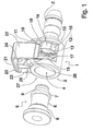
- Fig. 1 shows in a perspective view an embodiment of a coupling according to the invention with an elongate coupling part 1, which has on one side via a connecting piece 2.
- Cross-section formed and end-angled connection piece 2 is, for example, one end of a flexible hose of a in Fig. 1 not shown fluid conduit system pushed.
- the coupling part 1 is formed with a circular cross-section insertion opening 4, in which a Fig. 1 at a distance from the coupling part 1 shown counterpart with an elongated, substantially cylinder-like insertion section 5 is inserted.
- the insertion section 5 of the counterpart has a circumferential securing recess 6 which is delimited on the edge side by a first edge collar 7 arranged in the region of the free end of the insertion section 5 and a second edge collar 8 opposite the first edge collar 7.
- the introduction section 5 is designed, for example, as an end connection attached to a fluid reservoir of the fluid line system or can be connected to one end of a further flexible hose of the fluid line system.
- the coupling part 1 is formed with a thickened relative to the connecting piece 2 coupling portion 10 in which laterally introduced and extending from a roof land 11 to a bottom web 12 and thus perpendicular to the longitudinal direction of the coupling part 1 extending guide recesses 13 are.
- the longitudinal direction of the coupling part 1 on both sides of the guide recesses 13 are compared to the outside of the coupling portion 10 inwardly offset, slightly outwardly curved sliding surfaces 14, 15 present, which are formed in their bottom web 12 facing end portions with locking recesses 16, 17 as a locking structure and in the roof land 11 facing end portions with the Freihalteveriana 18, 19 as a free-hold structure.
- the locking recesses 16, 17 and the clearance depressions 18, 19 are aligned in the longitudinal direction of the coupling part 1.
- FIG. 1 illustrated preferred embodiment having a substantially U-shaped, releasably attached to the coupling part 1 locking member 20 which has an externally flat roof portion 21 and two rectangularly formed on the roof portion 21, the outside also flat side portions 22, 23 has.
- an internally vaulted locking web 24, 25 is formed, which are adapted to the dimensions of the guide recesses 13 and engage in this.
- the inner diameter of the locking member 20 in the region of the concavities of the locking webs 24, 25 is slightly smaller than the outer diameter of the insertion 5 in the region of the securing recesses 6 to produce a bias voltage on the side portions 22, 23 in the region facing away from the roof portion 21 of the ends Arresting webs 24, 25 of these aligned in the longitudinal direction of the coupling part 1, protruding locking lugs 26, 27 formed as a latching structure, which are dimensioned for engagement in the locking recesses 16, 17 and the Freihalteverianaitch 18, 19.
- Fig. 1 In the illustration according to Fig. 1 is the locking member 20 in a fixed release position in which the latching lugs 26, 27 with the Freihalteveriana 11, 18, 19 are engaged.
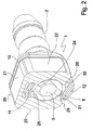
- Fig. 2 shows in a perspective view of the embodiment according to Fig. 1 in section through the coupling part 1 and located in a locking position locking part 20 and by the inserted into the coupling part 1 insertion section 5.
- the locking part 20 starting from the in Fig. 1 illustrated release position, the locking position has occupied by, for example with a fingertip or with a tool on the roof portion 21 in the direction of the side portions 21, 22 to overcome the engagement of the locking lugs 26, 27 with the Freihalteverianaieux 18, 19 sufficient force is exerted further acting force the inner sides of the side portions 22, 23 slide along the Geleits vom 14, 15 and the locking webs 24, 25 further engage in the guide recesses 13 of the coupling part 1.
- the in Fig. 2 non-visible locking lugs 26, 27 in the likewise not visible locking recesses 16, 17, so that even in the locking position, the locking member 20 is fixed.
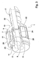
- Fig. 3 shows in a perspective, in the longitudinal direction in the transition region of a side portion 22 in the roof portion 21 partially cutaway view of the embodiment according to Fig. 1 and Fig. 2 with the locking member 20 in the locking position.
- a sealing ring 32 is arranged between the coupling part 1 and the insertion section 5 in order to achieve a tight connection in the fluid line system.
- the connecting piece 2 facing edge sides of the locking webs 24, 25 abut against the free end of the insertion section 5 adjacent first edge collar 7 and thereby hold the insertion section 5 substantially free of play in the coupling part 1.
Landscapes
- Engineering & Computer Science (AREA)
- General Engineering & Computer Science (AREA)
- Mechanical Engineering (AREA)
- Quick-Acting Or Multi-Walled Pipe Joints (AREA)
Claims (6)
- Raccord destiné à un système de conduites véhiculant un fluide, comprenant un organe d'accouplement (1) dans lequel la portion d'emmanchement (5) d'un élément d'accouplement conjugué est destinée à être introduite, dans lequel l'organe d'accouplement (1) est muni d'évidements d'introduction (13) se faisant respectivement face et comprenant un organe de verrouillage (20) qui est disposé mobile sur l'organe d'accouplement (1) et qui comporte une structure d'immobilisation en position, qui, dans une position de blocage en position opèrent en combinaison avec une structure agencée en correspondance d'accouplement ménagée dans la portion d'emmanchement (5) pour verrouiller l'élément d'accouplement conjugué et l'organe d'accouplement (1), dans lequel il est prévu, dans la zone des extrémités libres des deux portions latérales respectivement parallèles une structure d'accrochage (26, 27), caractérisé en ce qu'il est prévu au niveau des faces intérieures des portions latérales (22, 23) orientées en direction de l'organe d'accouplement (1) respectivement une nervure (24, 25) d'immobilisation en position qui s'étend dans le sens longitudinal du raccord et qui vient en prise d'engagement dans l'évidement d'introduction (13) et en ce que l'organe d'accouplement (1) est muni, dans la zone d'une extrémité des évidements d'introduction (13), d'une structure d'immobilisation en position (16, 17) dont la configuration est étudiée pour venir en correspondance d'accouplement avec la structure d'accrochage (26, 27).
- Raccord selon la revendication 1, caractérisé en ce que l'organe d'accouplement (1) est muni, dans la zone de l'autre extrémité des évidements d'introduction (13), d'une structure d'empêchement de blocage (18, 19) dont la configuration est étudiée en fonction de celle de la structure d'immobilisation en position (16, 17).
- Raccord selon la revendication 2, caractérisé en ce que la structure d'accrochage (26, 27) est constituée par des ergots d'accrochage, la structure d'immobilisation en position (16, 17) par des dépressions de verrouillage et la structure d'empêchement de blocage (18, 19) par des dépressions d'empêchement de blocage, qui sont orientées perpendiculairement aux nervures d'immobilisation en position (24, 25) dans le sens longitudinal de l'organe d'accouplement (1).
- Raccord selon l'une des revendications 1 à 3, caractérisé en ce qu'il est prévu une structure en relief (30, 31) dans la zone des extrémités libres de l'organe de verrouillage (20).
- Raccord selon l'une des revendications 1 à 4, caractérisé en ce que l'organe de verrouillage (20) comporte une portion de couverture plate (21) orientée perpendiculairement aux portions latérales (22, 23).
- Raccord selon l'une des revendications 1 à 5, caractérisé en ce que les nervures d'immobilisation en position (24, 25) présentent une conicité orientée dans la direction du côté d'introduction (3) de l'organe d'accouplement (1).
Applications Claiming Priority (2)
| Application Number | Priority Date | Filing Date | Title |
|---|---|---|---|
| DE102004020505A DE102004020505B4 (de) | 2004-04-22 | 2004-04-22 | Kupplung für ein Fluidleitungssystem |
| PCT/EP2005/002860 WO2005106312A1 (fr) | 2004-04-22 | 2005-03-17 | Dispositif d'accouplement pour systeme de guidage fluidique |
Publications (2)
| Publication Number | Publication Date |
|---|---|
| EP1740876A1 EP1740876A1 (fr) | 2007-01-10 |
| EP1740876B1 true EP1740876B1 (fr) | 2010-07-07 |
Family
ID=34961648
Family Applications (1)
| Application Number | Title | Priority Date | Filing Date |
|---|---|---|---|
| EP05716164A Expired - Lifetime EP1740876B1 (fr) | 2004-04-22 | 2005-03-17 | Dispositif d'accouplement pour systeme de guidage fluidique |
Country Status (14)
| Country | Link |
|---|---|
| US (1) | US7651138B2 (fr) |
| EP (1) | EP1740876B1 (fr) |
| JP (1) | JP4490480B2 (fr) |
| KR (1) | KR100759011B1 (fr) |
| CN (1) | CN100453878C (fr) |
| AT (1) | ATE473389T1 (fr) |
| AU (1) | AU2005238591B2 (fr) |
| BR (1) | BRPI0506933A (fr) |
| CA (1) | CA2562174C (fr) |
| DE (2) | DE102004020505B4 (fr) |
| ES (1) | ES2348450T3 (fr) |
| MX (1) | MXPA06012150A (fr) |
| RU (1) | RU2352850C2 (fr) |
| WO (1) | WO2005106312A1 (fr) |
Cited By (3)
| Publication number | Priority date | Publication date | Assignee | Title |
|---|---|---|---|---|
| DE102017006675A1 (de) | 2017-07-14 | 2019-01-17 | A. Raymond Et Cie | Verbinder, System aus einem Verbinder und einem einen Kopf aufweisenden Raststift eines zweiten Bauteils, Verfahren unter Einsatz eines derartigen Systems |
| EP3514025A1 (fr) | 2018-01-18 | 2019-07-24 | S.E.P. d.o.o. | Connecteur pour connexion rapide de conduites de fluide |
| DE102018121293A1 (de) * | 2018-08-31 | 2020-03-05 | Schlemmer Holding GmbH | Kupplungsvorrichtung und wellschlauchanordnung |
Families Citing this family (43)
| Publication number | Priority date | Publication date | Assignee | Title |
|---|---|---|---|---|
| JP4011575B2 (ja) * | 2004-10-15 | 2007-11-21 | 三桜工業株式会社 | クイックコネクタ |
| US7448653B2 (en) | 2005-06-10 | 2008-11-11 | Value Plastics, Inc. | Female connector for releasable coupling with a male connector defining a fluid conduit |
| US7806139B2 (en) | 2006-01-20 | 2010-10-05 | Value Plastics, Inc. | Fluid conduit coupling assembly having male and female couplers with integral valves |
| FR2905747B1 (fr) * | 2006-09-11 | 2011-04-22 | Gripp | Collecteur de distribution d'un fluide tel que de l'eau |
| DE102006044267B4 (de) | 2006-09-20 | 2010-08-05 | A. Raymond Et Cie | Kupplungsteil für eine Fluidleitungsverbindungsanordnung |
| USD654573S1 (en) | 2007-11-19 | 2012-02-21 | Value Plastics, Inc. | Female quick connect fitting |
| US8235426B2 (en) | 2008-07-03 | 2012-08-07 | Nordson Corporation | Latch assembly for joining two conduits |
| DE102008061462B4 (de) * | 2008-12-10 | 2011-04-14 | Illinois Tool Works Inc., Glenview | Kühlsystem für einen Verbrennungsmotor |
| USD655393S1 (en) | 2009-06-23 | 2012-03-06 | Value Plastics, Inc. | Multi-port valve |
| US8123259B2 (en) * | 2009-09-03 | 2012-02-28 | General Electric Company | Loose anti-rotation lock sleeve for pipe/flange assembly |
| US9494268B2 (en) * | 2009-10-21 | 2016-11-15 | Brasscraft Manufacturing Company | Supply stop with connection verification |
| US9523454B2 (en) * | 2009-10-21 | 2016-12-20 | Brasscraft Manufacturing Company | Anti-rotation gripper ring |
| US9506592B2 (en) | 2009-10-21 | 2016-11-29 | Brass-Craft Manufacturing Company | Supply stop with connection verification |
| US9464743B2 (en) * | 2009-10-21 | 2016-10-11 | Brass-Craft Manufacturing Company | Bias release cartridge |
| US10711930B2 (en) | 2009-12-09 | 2020-07-14 | Nordson Corporation | Releasable connection assembly |
| USD649240S1 (en) | 2009-12-09 | 2011-11-22 | Value Plastics, Inc. | Male dual lumen bayonet connector |
| USD650478S1 (en) | 2009-12-23 | 2011-12-13 | Value Plastics, Inc. | Female dual lumen connector |
| USD783815S1 (en) | 2009-12-09 | 2017-04-11 | General Electric Company | Male dual lumen bayonet connector |
| US9388929B2 (en) | 2009-12-09 | 2016-07-12 | Nordson Corporation | Male bayonet connector |
| EP2516913B1 (fr) | 2009-12-23 | 2014-09-17 | Nordson Corporation | Verrous de raccord de fluide comportant des profils de zones d'entrée |
| CN102753876B (zh) | 2009-12-23 | 2015-07-22 | 诺信公司 | 具有一体式模制悬臂弹簧的按钮闩 |
| EP2519766B1 (fr) * | 2009-12-31 | 2014-12-24 | Teklas Kaucuk Sanayi Ve Ticaret A.S. | Élément raccord rapide |
| USD652511S1 (en) | 2011-02-11 | 2012-01-17 | Value Plastics, Inc. | Female body of connector for fluid tubing |
| USD663022S1 (en) | 2011-02-11 | 2012-07-03 | Nordson Corporation | Male body of connector for fluid tubing |
| USD652510S1 (en) | 2011-02-11 | 2012-01-17 | Value Plastics, Inc. | Connector for fluid tubing |
| WO2013013185A1 (fr) | 2011-07-21 | 2013-01-24 | Kohler Co. | Connecteur rapide pour robinet |
| USD699840S1 (en) | 2011-07-29 | 2014-02-18 | Nordson Corporation | Male body of connector for fluid tubing |
| USD699841S1 (en) | 2011-07-29 | 2014-02-18 | Nordson Corporation | Female body of connector for fluid tubing |
| USD698440S1 (en) | 2011-07-29 | 2014-01-28 | Nordson Corporation | Connector for fluid tubing |
| DE112012003590B4 (de) * | 2011-08-29 | 2022-12-22 | Piolax, Inc. | Verbinder |
| USD709612S1 (en) | 2011-12-23 | 2014-07-22 | Nordson Corporation | Female dual lumen connector |
| JP5497223B1 (ja) * | 2013-04-16 | 2014-05-21 | 三桜工業株式会社 | 配管継手 |
| US9664321B2 (en) | 2013-05-20 | 2017-05-30 | Steere Enterprises, Inc. | Clean air duct and retaining clip and assembly thereof |
| US10859194B2 (en) | 2013-05-20 | 2020-12-08 | Steere Enterprises, Inc. | Clean air duct and retaining clip and assembly thereof |
| US9551443B2 (en) * | 2014-02-19 | 2017-01-24 | Ford Global Technologies, Llc | Engine fluid line with flexible joint |
| FR3021386B1 (fr) * | 2014-05-22 | 2017-02-24 | A Raymond Et Cie | Raccord tubulaire a connexion automatique |
| USD733842S1 (en) * | 2014-06-19 | 2015-07-07 | Life Technologies Corporation | Tube connector |
| US10422459B2 (en) | 2015-01-14 | 2019-09-24 | Norma U.S. Holding Llc | Conduit connector with a primary and secondary latch |
| USD838366S1 (en) | 2016-10-31 | 2019-01-15 | Nordson Corporation | Blood pressure connector |
| CN107575690A (zh) * | 2017-08-24 | 2018-01-12 | 吴清山 | 一种t型管材快速紧压器 |
| US11560967B2 (en) | 2018-09-04 | 2023-01-24 | Brasscraft Manufacturing Company | Rotation-resistant push-on conduit coupling cartridge |
| US20220073630A1 (en) * | 2018-12-28 | 2022-03-10 | Hoffmann-La Roche, Inc. | A peptide-mhc-i-antibody fusion protein for therapeutic use in a patient with amplified immune response |
| USD952805S1 (en) * | 2020-01-02 | 2022-05-24 | Changzheng Lin | Water pipe quick connector |
Family Cites Families (25)
| Publication number | Priority date | Publication date | Assignee | Title |
|---|---|---|---|---|
| US4936544A (en) * | 1980-10-29 | 1990-06-26 | Proprietary Technology, Inc. | Swivelable quick connector assembly |
| US4423892A (en) * | 1980-10-29 | 1984-01-03 | Bartholomew Donald D | Swivelable quick connector assembly |
| US4561682A (en) * | 1982-09-03 | 1985-12-31 | Rain Bird Consumer Products Mfg. Corp. | Quick connect coupling |
| US5423577A (en) * | 1992-01-17 | 1995-06-13 | Bundy Corporation | Tubing connector |
| US5269571A (en) * | 1992-09-22 | 1993-12-14 | Purolator Products, Inc. | Fuel filter retaining clip having rotating flipper portions |
| KR100267605B1 (ko) * | 1992-09-24 | 2000-10-16 | 안자이 이치로 | 파이프 조인트 |
| US5441313A (en) * | 1994-01-18 | 1995-08-15 | Bundy Corporation | Insertion indicator for quick connector |
| US5730481A (en) * | 1994-11-04 | 1998-03-24 | Itt Automotive, Inc. | Quick connector with snap-on retainer |
| US5542716A (en) * | 1994-11-04 | 1996-08-06 | Itt Corporation | Quick connector with snap-on retainer |
| US5586792A (en) * | 1995-02-21 | 1996-12-24 | Bundy Corporation | Quick connector with integral release mechanism |
| EP0743481B1 (fr) * | 1995-05-17 | 2001-03-28 | Showa Aluminum Corporation | Raccord de tuyaux |
| US5951063A (en) * | 1995-06-07 | 1999-09-14 | Itt Manufacturing Enterprises, Inc. | Quick connector with snap-on retainer having enhanced engagement |
| US5683117A (en) * | 1995-12-14 | 1997-11-04 | Flex Technologies, Inc. | Retainer clip for a connector |
| CN2394079Y (zh) * | 1998-06-22 | 2000-08-30 | 李明义 | 一种嵌插式快速接头结构 |
| SE9802403D0 (sv) * | 1998-07-03 | 1998-07-03 | Wirsbo Bruks Ab | Rörledningskoppling |
| US6612622B2 (en) * | 2000-04-06 | 2003-09-02 | Itt Manufacturing Enterprises, Inc. | Rotatable quick connector |
| DE10024303B4 (de) * | 2000-05-17 | 2005-09-08 | Rasmussen Gmbh | Aufnahme-Kupplungsvorrichtung einer Steckkupplung und Steckkupplung mit der Aufnahme-Kupplungsvorrichtung |
| JP3958028B2 (ja) * | 2001-01-15 | 2007-08-15 | 三桜工業株式会社 | 配管用継手 |
| DE10141315C1 (de) * | 2001-08-28 | 2003-03-20 | Siemens Ag | Kupplung zum Verbinden zweier ein Medium führender Bauteile |
| FR2843624A1 (fr) * | 2002-08-13 | 2004-02-20 | Valeo Embrayages | Dispositif de branchement d'alimentation pour un systeme a pression de fluide |
| JP4291989B2 (ja) * | 2002-10-01 | 2009-07-08 | 株式会社パイオラックス | 配管用コネクタ |
| US7464970B2 (en) * | 2003-10-22 | 2008-12-16 | Togo Seisakusyo Corporation | Pipe joint |
| US7390025B2 (en) * | 2004-03-31 | 2008-06-24 | Ti Group Automotive Systems, Llc | Secondary latch/verifier for a quick connector |
| JP2006313010A (ja) * | 2005-04-04 | 2006-11-16 | Denso Corp | 配管継手装置 |
| US7484774B2 (en) * | 2005-05-03 | 2009-02-03 | Ti Group Automotive Systems, Llc | Redundant latch/verifier for a quick connector |
-
2004
- 2004-04-22 DE DE102004020505A patent/DE102004020505B4/de not_active Expired - Fee Related
-
2005
- 2005-03-17 BR BRPI0506933-5A patent/BRPI0506933A/pt active IP Right Grant
- 2005-03-17 AT AT05716164T patent/ATE473389T1/de active
- 2005-03-17 WO PCT/EP2005/002860 patent/WO2005106312A1/fr not_active Ceased
- 2005-03-17 MX MXPA06012150A patent/MXPA06012150A/es active IP Right Grant
- 2005-03-17 EP EP05716164A patent/EP1740876B1/fr not_active Expired - Lifetime
- 2005-03-17 ES ES05716164T patent/ES2348450T3/es not_active Expired - Lifetime
- 2005-03-17 DE DE502005009866T patent/DE502005009866D1/de not_active Expired - Lifetime
- 2005-03-17 KR KR1020067020319A patent/KR100759011B1/ko not_active Expired - Lifetime
- 2005-03-17 CA CA002562174A patent/CA2562174C/fr not_active Expired - Lifetime
- 2005-03-17 RU RU2006130007/06A patent/RU2352850C2/ru active
- 2005-03-17 CN CNB2005800090524A patent/CN100453878C/zh not_active Expired - Lifetime
- 2005-03-17 AU AU2005238591A patent/AU2005238591B2/en not_active Ceased
- 2005-03-17 JP JP2007508745A patent/JP4490480B2/ja not_active Expired - Lifetime
- 2005-03-17 US US10/589,228 patent/US7651138B2/en not_active Expired - Lifetime
Cited By (6)
| Publication number | Priority date | Publication date | Assignee | Title |
|---|---|---|---|---|
| DE102017006675A1 (de) | 2017-07-14 | 2019-01-17 | A. Raymond Et Cie | Verbinder, System aus einem Verbinder und einem einen Kopf aufweisenden Raststift eines zweiten Bauteils, Verfahren unter Einsatz eines derartigen Systems |
| WO2019011978A1 (fr) | 2017-07-14 | 2019-01-17 | A. Raymond Et Cie | Connecteur, système composé d'un connecteur et d'une tige d'encliquetage contenant une tête d'un deuxième composant, procédé utilisant un tel système |
| US11248642B2 (en) | 2017-07-14 | 2022-02-15 | A. Raymond Et Cie | Connector, system consisting of a connector and a latching pin of a second component, said latching pin having a head, and method for using such a system |
| DE102017006675B4 (de) | 2017-07-14 | 2023-12-21 | A. Raymond Et Cie | Verbinder, System aus einem Verbinder und einem einen Kopf aufweisenden Raststift eines zweiten Bauteils, Verfahren unter Einsatz eines derartigen Systems |
| EP3514025A1 (fr) | 2018-01-18 | 2019-07-24 | S.E.P. d.o.o. | Connecteur pour connexion rapide de conduites de fluide |
| DE102018121293A1 (de) * | 2018-08-31 | 2020-03-05 | Schlemmer Holding GmbH | Kupplungsvorrichtung und wellschlauchanordnung |
Also Published As
| Publication number | Publication date |
|---|---|
| CA2562174C (fr) | 2009-11-17 |
| KR100759011B1 (ko) | 2007-09-14 |
| CA2562174A1 (fr) | 2005-11-10 |
| BRPI0506933A (pt) | 2007-06-12 |
| HK1096721A1 (zh) | 2007-06-08 |
| RU2006130007A (ru) | 2008-05-27 |
| AU2005238591B2 (en) | 2008-07-31 |
| ATE473389T1 (de) | 2010-07-15 |
| RU2352850C2 (ru) | 2009-04-20 |
| KR20070004797A (ko) | 2007-01-09 |
| MXPA06012150A (es) | 2007-12-04 |
| DE102004020505A1 (de) | 2005-11-17 |
| EP1740876A1 (fr) | 2007-01-10 |
| DE502005009866D1 (de) | 2010-08-19 |
| WO2005106312A1 (fr) | 2005-11-10 |
| DE102004020505B4 (de) | 2009-05-28 |
| ES2348450T3 (es) | 2010-12-07 |
| US7651138B2 (en) | 2010-01-26 |
| JP4490480B2 (ja) | 2010-06-23 |
| CN1934387A (zh) | 2007-03-21 |
| AU2005238591A1 (en) | 2005-11-10 |
| CN100453878C (zh) | 2009-01-21 |
| JP2007533924A (ja) | 2007-11-22 |
| US20080111371A1 (en) | 2008-05-15 |
Similar Documents
| Publication | Publication Date | Title |
|---|---|---|
| EP1740876B1 (fr) | Dispositif d'accouplement pour systeme de guidage fluidique | |
| EP1969279B1 (fr) | Piece de couplage pour systeme de connecteur enfichable | |
| DE10024303B4 (de) | Aufnahme-Kupplungsvorrichtung einer Steckkupplung und Steckkupplung mit der Aufnahme-Kupplungsvorrichtung | |
| EP2179211B1 (fr) | Raccord de conduite de fluide | |
| EP1825182A1 (fr) | Element de verrouillage pour un couplage rapide | |
| WO2011006591A1 (fr) | Accouplement enfichable | |
| EP2802801B1 (fr) | Connexion par enfichage libérable | |
| WO2021190897A1 (fr) | Raccord de type enfichable ayant un verrouillage de préassemblage | |
| EP2466183A2 (fr) | Accouplement rapide pour conduites de fluide | |
| EP3318368B1 (fr) | Système de couplage de manche amovible pour appareils de travail | |
| EP1969280B1 (fr) | Fiche pour systeme de connecteur enfichable | |
| EP1952050B1 (fr) | Raccord rapide pour tuyaux | |
| DE4409837C2 (de) | Befestigungskupplung für Wellrohre | |
| DE102010026100A1 (de) | Schnellkupplung für Fluidleitungen | |
| WO2023046549A1 (fr) | Raccord mâle à verrouillage de pré-assemblage | |
| DE202011107042U1 (de) | Verbindungseinheit, Verbindungsanordnung mit einer derartigen Verbindungseinheit und Verbindungsbausatz mit einer derartigen Verbindungseinheit oder einer derartigen Verbindungsanordnung | |
| DE10011288A1 (de) | Knebelverbindung für Rinnen- und Führungsschüsse sowie Knebel, Knebeltaschen, Sicherungsglieder, Schüsse und Montagewerkzeug für Knebelverbindungen | |
| EP2603129B1 (fr) | Tubulure de connexion pour aspirateur | |
| DE19930023C2 (de) | Rohrverbindung in Form einer Steckmuffenverbindung | |
| WO2026060469A1 (fr) | Connecteur mâle pour raccorder de manière fluidique un composant de transport de fluide à une conduite de fluide | |
| EP0293928A1 (fr) | Wishbone de longueur réglable | |
| DE29613746U1 (de) | Schlauchfassung zur lösbaren Befestigung eines Außenschlauches eines Betätigungszuges | |
| EP2417889A2 (fr) | Tubulure de raccordement dotée d'élément de ressort | |
| DE19524031A1 (de) | Kupplung |
Legal Events
| Date | Code | Title | Description |
|---|---|---|---|
| PUAI | Public reference made under article 153(3) epc to a published international application that has entered the european phase |
Free format text: ORIGINAL CODE: 0009012 |
|
| 17P | Request for examination filed |
Effective date: 20061122 |
|
| AK | Designated contracting states |
Kind code of ref document: A1 Designated state(s): AT BE BG CH CY CZ DE DK EE ES FI FR GB GR HU IE IS IT LI LT LU MC NL PL PT RO SE SI SK TR |
|
| RAP1 | Party data changed (applicant data changed or rights of an application transferred) |
Owner name: A. RAYMOND ET CIE Owner name: VOLKSWAGEN AKTIENGESELLSCHAFT |
|
| DAX | Request for extension of the european patent (deleted) | ||
| 17Q | First examination report despatched |
Effective date: 20071213 |
|
| GRAP | Despatch of communication of intention to grant a patent |
Free format text: ORIGINAL CODE: EPIDOSNIGR1 |
|
| GRAS | Grant fee paid |
Free format text: ORIGINAL CODE: EPIDOSNIGR3 |
|
| GRAA | (expected) grant |
Free format text: ORIGINAL CODE: 0009210 |
|
| AK | Designated contracting states |
Kind code of ref document: B1 Designated state(s): AT BE BG CH CY CZ DE DK EE ES FI FR GB GR HU IE IS IT LI LT LU MC NL PL PT RO SE SI SK TR |
|
| REG | Reference to a national code |
Ref country code: GB Ref legal event code: FG4D Free format text: NOT ENGLISH |
|
| REG | Reference to a national code |
Ref country code: CH Ref legal event code: EP |
|
| REG | Reference to a national code |
Ref country code: IE Ref legal event code: FG4D |
|
| REF | Corresponds to: |
Ref document number: 502005009866 Country of ref document: DE Date of ref document: 20100819 Kind code of ref document: P |
|
| RAP2 | Party data changed (patent owner data changed or rights of a patent transferred) |
Owner name: VOLKSWAGEN AKTIENGESELLSCHAFT Owner name: A. RAYMOND ET CIE |
|
| REG | Reference to a national code |
Ref country code: NL Ref legal event code: VDEP Effective date: 20100707 |
|
| REG | Reference to a national code |
Ref country code: ES Ref legal event code: FG2A Effective date: 20101124 |
|
| PG25 | Lapsed in a contracting state [announced via postgrant information from national office to epo] |
Ref country code: SI Free format text: LAPSE BECAUSE OF FAILURE TO SUBMIT A TRANSLATION OF THE DESCRIPTION OR TO PAY THE FEE WITHIN THE PRESCRIBED TIME-LIMIT Effective date: 20100707 |
|
| LTIE | Lt: invalidation of european patent or patent extension |
Effective date: 20100707 |
|
| PG25 | Lapsed in a contracting state [announced via postgrant information from national office to epo] |
Ref country code: NL Free format text: LAPSE BECAUSE OF FAILURE TO SUBMIT A TRANSLATION OF THE DESCRIPTION OR TO PAY THE FEE WITHIN THE PRESCRIBED TIME-LIMIT Effective date: 20100707 Ref country code: LT Free format text: LAPSE BECAUSE OF FAILURE TO SUBMIT A TRANSLATION OF THE DESCRIPTION OR TO PAY THE FEE WITHIN THE PRESCRIBED TIME-LIMIT Effective date: 20100707 Ref country code: FI Free format text: LAPSE BECAUSE OF FAILURE TO SUBMIT A TRANSLATION OF THE DESCRIPTION OR TO PAY THE FEE WITHIN THE PRESCRIBED TIME-LIMIT Effective date: 20100707 |
|
| REG | Reference to a national code |
Ref country code: IE Ref legal event code: FD4D |
|
| PG25 | Lapsed in a contracting state [announced via postgrant information from national office to epo] |
Ref country code: IS Free format text: LAPSE BECAUSE OF FAILURE TO SUBMIT A TRANSLATION OF THE DESCRIPTION OR TO PAY THE FEE WITHIN THE PRESCRIBED TIME-LIMIT Effective date: 20101107 Ref country code: PT Free format text: LAPSE BECAUSE OF FAILURE TO SUBMIT A TRANSLATION OF THE DESCRIPTION OR TO PAY THE FEE WITHIN THE PRESCRIBED TIME-LIMIT Effective date: 20101108 Ref country code: BG Free format text: LAPSE BECAUSE OF FAILURE TO SUBMIT A TRANSLATION OF THE DESCRIPTION OR TO PAY THE FEE WITHIN THE PRESCRIBED TIME-LIMIT Effective date: 20101007 Ref country code: CY Free format text: LAPSE BECAUSE OF FAILURE TO SUBMIT A TRANSLATION OF THE DESCRIPTION OR TO PAY THE FEE WITHIN THE PRESCRIBED TIME-LIMIT Effective date: 20100707 Ref country code: PL Free format text: LAPSE BECAUSE OF FAILURE TO SUBMIT A TRANSLATION OF THE DESCRIPTION OR TO PAY THE FEE WITHIN THE PRESCRIBED TIME-LIMIT Effective date: 20100707 |
|
| PG25 | Lapsed in a contracting state [announced via postgrant information from national office to epo] |
Ref country code: GR Free format text: LAPSE BECAUSE OF FAILURE TO SUBMIT A TRANSLATION OF THE DESCRIPTION OR TO PAY THE FEE WITHIN THE PRESCRIBED TIME-LIMIT Effective date: 20101008 Ref country code: SE Free format text: LAPSE BECAUSE OF FAILURE TO SUBMIT A TRANSLATION OF THE DESCRIPTION OR TO PAY THE FEE WITHIN THE PRESCRIBED TIME-LIMIT Effective date: 20100707 |
|
| PG25 | Lapsed in a contracting state [announced via postgrant information from national office to epo] |
Ref country code: DK Free format text: LAPSE BECAUSE OF FAILURE TO SUBMIT A TRANSLATION OF THE DESCRIPTION OR TO PAY THE FEE WITHIN THE PRESCRIBED TIME-LIMIT Effective date: 20100707 Ref country code: IE Free format text: LAPSE BECAUSE OF FAILURE TO SUBMIT A TRANSLATION OF THE DESCRIPTION OR TO PAY THE FEE WITHIN THE PRESCRIBED TIME-LIMIT Effective date: 20100707 |
|
| PLBE | No opposition filed within time limit |
Free format text: ORIGINAL CODE: 0009261 |
|
| STAA | Information on the status of an ep patent application or granted ep patent |
Free format text: STATUS: NO OPPOSITION FILED WITHIN TIME LIMIT |
|
| PG25 | Lapsed in a contracting state [announced via postgrant information from national office to epo] |
Ref country code: SK Free format text: LAPSE BECAUSE OF FAILURE TO SUBMIT A TRANSLATION OF THE DESCRIPTION OR TO PAY THE FEE WITHIN THE PRESCRIBED TIME-LIMIT Effective date: 20100707 Ref country code: RO Free format text: LAPSE BECAUSE OF FAILURE TO SUBMIT A TRANSLATION OF THE DESCRIPTION OR TO PAY THE FEE WITHIN THE PRESCRIBED TIME-LIMIT Effective date: 20100707 Ref country code: EE Free format text: LAPSE BECAUSE OF FAILURE TO SUBMIT A TRANSLATION OF THE DESCRIPTION OR TO PAY THE FEE WITHIN THE PRESCRIBED TIME-LIMIT Effective date: 20100707 |
|
| 26N | No opposition filed |
Effective date: 20110408 |
|
| REG | Reference to a national code |
Ref country code: DE Ref legal event code: R097 Ref document number: 502005009866 Country of ref document: DE Effective date: 20110408 |
|
| BERE | Be: lapsed |
Owner name: VOLKSWAGEN A.G. Effective date: 20110331 Owner name: A. RAYMOND ET CIE Effective date: 20110331 |
|
| PG25 | Lapsed in a contracting state [announced via postgrant information from national office to epo] |
Ref country code: MC Free format text: LAPSE BECAUSE OF NON-PAYMENT OF DUE FEES Effective date: 20110331 |
|
| REG | Reference to a national code |
Ref country code: CH Ref legal event code: PL |
|
| GBPC | Gb: european patent ceased through non-payment of renewal fee |
Effective date: 20110317 |
|
| PG25 | Lapsed in a contracting state [announced via postgrant information from national office to epo] |
Ref country code: BE Free format text: LAPSE BECAUSE OF NON-PAYMENT OF DUE FEES Effective date: 20110331 |
|
| PG25 | Lapsed in a contracting state [announced via postgrant information from national office to epo] |
Ref country code: LI Free format text: LAPSE BECAUSE OF NON-PAYMENT OF DUE FEES Effective date: 20110331 Ref country code: CH Free format text: LAPSE BECAUSE OF NON-PAYMENT OF DUE FEES Effective date: 20110331 |
|
| PG25 | Lapsed in a contracting state [announced via postgrant information from national office to epo] |
Ref country code: GB Free format text: LAPSE BECAUSE OF NON-PAYMENT OF DUE FEES Effective date: 20110317 |
|
| REG | Reference to a national code |
Ref country code: AT Ref legal event code: MM01 Ref document number: 473389 Country of ref document: AT Kind code of ref document: T Effective date: 20110317 |
|
| PG25 | Lapsed in a contracting state [announced via postgrant information from national office to epo] |
Ref country code: AT Free format text: LAPSE BECAUSE OF NON-PAYMENT OF DUE FEES Effective date: 20110317 |
|
| PG25 | Lapsed in a contracting state [announced via postgrant information from national office to epo] |
Ref country code: LU Free format text: LAPSE BECAUSE OF NON-PAYMENT OF DUE FEES Effective date: 20110317 |
|
| PG25 | Lapsed in a contracting state [announced via postgrant information from national office to epo] |
Ref country code: TR Free format text: LAPSE BECAUSE OF FAILURE TO SUBMIT A TRANSLATION OF THE DESCRIPTION OR TO PAY THE FEE WITHIN THE PRESCRIBED TIME-LIMIT Effective date: 20100707 |
|
| PG25 | Lapsed in a contracting state [announced via postgrant information from national office to epo] |
Ref country code: HU Free format text: LAPSE BECAUSE OF FAILURE TO SUBMIT A TRANSLATION OF THE DESCRIPTION OR TO PAY THE FEE WITHIN THE PRESCRIBED TIME-LIMIT Effective date: 20100707 |
|
| REG | Reference to a national code |
Ref country code: DE Ref legal event code: R082 Ref document number: 502005009866 Country of ref document: DE |
|
| REG | Reference to a national code |
Ref country code: FR Ref legal event code: PLFP Year of fee payment: 12 |
|
| REG | Reference to a national code |
Ref country code: FR Ref legal event code: PLFP Year of fee payment: 13 |
|
| REG | Reference to a national code |
Ref country code: FR Ref legal event code: PLFP Year of fee payment: 14 |
|
| P01 | Opt-out of the competence of the unified patent court (upc) registered |
Effective date: 20230524 |
|
| PGFP | Annual fee paid to national office [announced via postgrant information from national office to epo] |
Ref country code: DE Payment date: 20240320 Year of fee payment: 20 Ref country code: CZ Payment date: 20240307 Year of fee payment: 20 |
|
| PGFP | Annual fee paid to national office [announced via postgrant information from national office to epo] |
Ref country code: IT Payment date: 20240329 Year of fee payment: 20 Ref country code: FR Payment date: 20240321 Year of fee payment: 20 |
|
| PGFP | Annual fee paid to national office [announced via postgrant information from national office to epo] |
Ref country code: ES Payment date: 20240426 Year of fee payment: 20 |
|
| REG | Reference to a national code |
Ref country code: DE Ref legal event code: R071 Ref document number: 502005009866 Country of ref document: DE |
|
| REG | Reference to a national code |
Ref country code: ES Ref legal event code: FD2A Effective date: 20250331 |
|
| PG25 | Lapsed in a contracting state [announced via postgrant information from national office to epo] |
Ref country code: ES Free format text: LAPSE BECAUSE OF EXPIRATION OF PROTECTION Effective date: 20250318 |
|
| PG25 | Lapsed in a contracting state [announced via postgrant information from national office to epo] |
Ref country code: CZ Free format text: LAPSE BECAUSE OF EXPIRATION OF PROTECTION Effective date: 20250317 |