EP1740995B1 - Auf flüssigkeit basierende optische einrichtung und elektronische einrichtung - Google Patents
Auf flüssigkeit basierende optische einrichtung und elektronische einrichtung Download PDFInfo
- Publication number
- EP1740995B1 EP1740995B1 EP05718727A EP05718727A EP1740995B1 EP 1740995 B1 EP1740995 B1 EP 1740995B1 EP 05718727 A EP05718727 A EP 05718727A EP 05718727 A EP05718727 A EP 05718727A EP 1740995 B1 EP1740995 B1 EP 1740995B1
- Authority
- EP
- European Patent Office
- Prior art keywords
- interface
- electric field
- optical device
- container
- liquid
- Prior art date
- Legal status (The legal status is an assumption and is not a legal conclusion. Google has not performed a legal analysis and makes no representation as to the accuracy of the status listed.)
- Expired - Lifetime
Links
Images
Classifications
-
- G—PHYSICS
- G02—OPTICS
- G02B—OPTICAL ELEMENTS, SYSTEMS OR APPARATUS
- G02B26/00—Optical devices or arrangements for the control of light using movable or deformable optical elements
- G02B26/004—Optical devices or arrangements for the control of light using movable or deformable optical elements based on a displacement or a deformation of a fluid
- G02B26/005—Optical devices or arrangements for the control of light using movable or deformable optical elements based on a displacement or a deformation of a fluid based on electrowetting
-
- G—PHYSICS
- G02—OPTICS
- G02B—OPTICAL ELEMENTS, SYSTEMS OR APPARATUS
- G02B3/00—Simple or compound lenses
- G02B3/12—Fluid-filled or evacuated lenses
- G02B3/14—Fluid-filled or evacuated lenses of variable focal length
Definitions
- the present invention relates to an optical device comprising a container enclosing an insulating liquid and a liquid responsive to an electric field, the insulating liquid and the liquid responsive to an electric field being immiscible and being in contact with each other via an interface, the liquids being placed in a light path through the container; an electrode arrangement for controlling the shape of the interface by means of a voltage.
- the present invention further relates to an electronic device comprising such an optical device.
- an optical device that incorporates two immiscible liquids with equal refractive indices but different transmittances, with one of the two liquids being conductive. By varying the interface between these two liquids, the amount of each of the liquids in the light path through the device is changed and a diaphragm is obtained as a result.
- International patent application WO03/069380 discloses a cylindrical variable focus lens incorporating two immiscible fluids having different refractive indices, one of the fluids being conductive and the other being insulating.
- the shape of the interface between the two fluids is manipulated by applying a voltage across the lens, which can be used to introduce a change in the focal point of the lens.
- the walls of the cylinder and one of the transparent lids of the cylinder are coated with a hydrophobic coating to ensure that at least in a switched off state the conductive fluid, which typically is a polar liquid, the contact area between said walls and the conductive fluid is minimized in order to achieve an interface with a large curvature, which contributes to a large optical power range for the lens.
- a problem that can occur with such devices is that after a period of time an unintended deformation of the interface can occur, which disturbs the desired optical behaviour of the interface.
- the invention seeks to provide an optical device in which the unintended deformation of the interface is avoided.
- the invention further seeks to provide an electronic device comprising such an improved optical device.
- an optical device according to claim 1.
- a liquid responsive to an electric field' is intended to include conductive liquids, polar liquids and polarizable liquids.
- the invention is based on the realization that the unintended deformation of the interface is caused by its exposure to an external electric field, which may be a static field caused by the build-up of an electrostatic charge on a surface of the container.
- the build-up of the electrostatic charge may for instance be caused by intentional or unintentional rubbing of the surface of the container.
- the means for controlling an orientation of the interface may comprise an electrode arrangement for controlling the shape of the interface by means of a voltage. This is especially advantageous in the case of the optical device being a variable focus lens, because this facilitates a lens with a large optical power.
- the conductive layer has the advantage that the accumulation of electrostatic charge on the transparent end portion can be avoided.
- the conductive layer is kept at the same potential as the liquid responsive to an electric field, thus ensuring that the presence of any electrostatic charge on the transparent end portion has no influence on the shape of the interface.
- the means for preventing the interface from an exposure to an external electric field comprise a Faraday cage surrounding the container.
- This embodiment which may be combined with the previous embodiment, protects the optical device from exposure to external electrical fields, and consequently prohibits the build-up of electrostatic charge on a surface of its container.
- the Faraday cage may comprise a conductive coating at least partially covering a further container. This has the advantage that the Faraday cage can be produced separately from the optical device.
- the further container may be at least partially transparent. This has the advantage that the further container can completely encapsulate the container of the optical device, without the optical path through the latter being compromised.
- an electronic device including an optical device comprising a container enclosing an insulating liquid and a liquid responsive to an electric field, the insulating liquid and the liquid responsive to an electric field being immiscible and being
- the electronic device further comprising driver circuitry coupled to the means for controlling an orientation of the interface and a power supply for powering the driver circuitry, the means for preventing the interface from an exposure to an external electric field being coupled to a terminal of the power supply, and wherein a surface is a part of a transparent end portion of the container; the means for preventing the interface from an exposure to an external electric field comprise a conductive layer, the conductive layer forming a part of the transparent end portion, wherein the means for controlling the orientation of the interface comprise an electrode in contact with the liquid responsive to an electric field (B), the conductive layer being conductively coupled to said electrode.
- B electric field
- the electronic device of the present invention has the advantage that the performance of its optical device is not hampered by external electric fields such as the accumulation of electrostatic charges on a surface of the container of the optical device.
- the means for preventing the interface from an exposure to an external electric field are coupled to a terminal of the power supply, preferably ground, to ensure that said means are kept on a same potential as the liquid responsive to an electric field.
- the means for preventing the interface from an exposure to an external electric field form a part of an arrangement for shielding an electronic circuit of the electronic device from external radiation.
- optical device can be protected from the build-up of electrostatic charge by extending an arrangement already present in the electronic device, which is cost-effective.
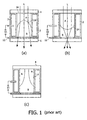
- variable focus lens as disclosed in International Patent application WO 03/O69380 is shown.
- the variable focus lens comprises a first fluid A and a second fluid B housed in a cylindrical chamber.
- the fluids are immiscible, have different refractive indices and preferably have the same density to avoid orientation-dependent gravitational effects on the orientation of the fluids including the interface 14 between the fluids.
- the cylindrical chamber further comprises a first end portion 4 and a second end portion 6, with the first end portion 4 as well as the inner walls of the cylindrical chamber being covered by a hydrophobic coating such as AF1600TM from the DuPont company, which may be combined with a stack of parylene, to confine the conductive fluid B by the insulating fluid A in the absence of an applied voltage.
- a hydrophobic coating such as AF1600TM from the DuPont company, which may be combined with a stack of parylene, to confine the conductive fluid B by the insulating fluid A in the absence of an applied voltage.
- the shape of the interface 14 can be switched in a continuous fashion from a convex shape shown in orientation (a) to a concave shape shown in orientation (b) by varying a direct or alternating voltage from a value V1 to a value V2 across the cylindrical electrode 2 embedded in the chamber wall and a, preferably transparent, annular electrode 12 on the second lid 6 which is in conductive contact with the second fluid B. Consequently, the focal point of the light path L through the cylinder is altered.
- the transparent end portion 4 may be a glass or polymer lid or another suitable transparent material, which may be lens-shaped.
- the exposure of the container of the fluids A and B to an external electrical field or the rubbing of the transparent end portion 4, e.g., cleaning the end portion with a cloth or accidental rubbing of the end portion 4 by wearing the optical device in a pocket of a garment, can cause the accumulation of an electrostatic charge on a surface of the container such as the transparent end portion 4.
- This charge can attract the conductive fluid B, thereby disturbing the shape of the interface 14 between the fluids A and B, as shown in (c), thus causing a deviation of the desired optical behaviour of the lens. Since it can take several hours or longer for the electrostatic charge to leak away, it will be obvious that this is a highly unwanted effect. It is pointed out that a similar unwanted effect can occur when the lens is exposed to an external electrical field.
- variable focus lens of Fig. 1 will be shown as an embodiment of the optical device of the present invention. It is emphasized, however, that the teachings of the present invention also apply to other liquid-based optical devices.
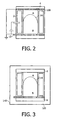
- the variable focus lens of Fig. 1 is extended with a conductive layer 100 for preventing the interface from an exposure to an external electric field of the lens, i.e., on the first end portion 4.
- the conductive layer 100 is shown on the inner surface of the end portion 4, but an orientation on the outer surface of the end portion 4 is also feasible.
- the conductive layer 100 can be realized with any known transparent conductive material such as indium tin oxide (ITO), Indium trioxide (In 2 O 3 ) or tin dioxide (SnO 2 ).
- ITO indium tin oxide
- In 2 O 3 Indium trioxide
- SnO 2 tin dioxide
- the conductive layer 100 is kept at the same potential as the liquid responsive to an electric field B by conductively coupling the conductive layer 100 to the electrode 12 in contact with the liquid responsive to an electric field B, as shown in Fig. 2 .
- Fig. 3 shows another optical device not representing an embodiment of the present invention.
- the variable focus lens of Fig.1 is placed inside a further container 120.
- the further container 120 may be open opposite the end portion 4 and the end portion 6 of the variable focus lens, or may have transparent sections opposite those end portions.
- the further container 120 may further comprise a metal body, or may further comprise a non-conductive material such as plastic or glass, which may be transparent.
- the further container 120 further comprises a conductive coating 140, which may be transparent, and which may reside on an inner surface or an outer surface of the further container 120.
- the further container 120 acts as a Faraday cage around the variable focus lens, thus preventing a build-up of an electrostatic charge on a surface of the container. Furthermore, since an external electrical field can also disrupt the intended optical behaviour of the optical device, the Faraday cage also protects the optical device against such disruptions.
- the conductive coating 140 may also be applied to the outer surface of the container of the variable focus lens, in which case the further container 120 can be omitted.
- the conductive coating 140 or a conductive further container 120 are conductively coupled to the liquid responsive to an electric field B to ensure that the Faraday cage is kept at the same potential as the liquid responsive to an electric field B. This conductive coupling may be realized via the electrode 12. It is emphasized that the aforementioned examples of a Faraday cage may be combined with any of the embodiments of the conductive layer 100 as shown in Fig. 2 in order to form an embodiment of the present invention.
- the means for controlling the orientation of the interface 14 are depicted as an electrode arrangement for controlling the shape of the interface 14 by means of a voltage, other means for controlling the orientation of the interface 14 are equally acceptable, such as the means for controlling the orientation of the interface 14 as described in . WO2004102250 .
- a variable focus lens including two immiscible liquids with different refractive indices.
- the lens has two chambers over which the two liquids are distributed: a first chamber in which the interface is positioned and through which the light path runs, and a second chamber having two connections to the first chamber.
- the second chamber includes a pump, which is used to alter the respective volumes of the liquids in both chambers. Consequently, the focus of the lens is varied by a translation of the pos ition of the interface between the two liquids with respect to the inner wall of the first chamber rather than by changing the shape, i.e., the curvature of the interface.
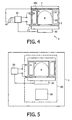
- Fig. 4 shows an embodiment of an electronic device 1 of the present invention, including an optical device having a conductive layer 100 on the end portion 4, as shown in Fig. 2 and its detailed description.
- the electronic device 1 further includes driver circuitry 20 for applying a voltage across the electrode arrangement including electrodes 2 and 12, and an image sensor 30 for capturing an image that enters the electronic device 1 via the light path of the optical device.
- the driver circuitry 20 and the image sensor 30 are powered by a power supply 40, which has one of its terminals, e.g., ground, coupled to the conductive layer 100. This may also be the ground of the electronic device 1.
- the conductive layer 100 may also be coupled to the power supply 40 via the electrode 12, in an arrangement analogous to that shown in Fig. 2 .
- Fig. 5 shows another electronic device not representing an embodiment of the present invention, including a liquid-based optical device, e.g., a variable focus lens, driver circuitry 20, an image sensor 30 and a power supply (not shown).
- the electronic device 1 further comprises an electronic circuit 50, which is shielded from external radiation, i.e., radiation from outside the electronic circuit, by shielding material 60.
- the shielding material 60 may be any suitable material known to the skilled person, e.g., a conductive foil or a metal housing.
- the shielding material 60 is extended over the container of the optical device without blocking the light path through the optical device to prevent a build-up of a n electrostatic charge on a surface of the container of the optical device.
Landscapes
- Physics & Mathematics (AREA)
- General Physics & Mathematics (AREA)
- Optics & Photonics (AREA)
- Mechanical Light Control Or Optical Switches (AREA)
- Studio Devices (AREA)
Claims (9)
- Optische Einrichtung mit:einem Behälter, der eine Isolierflüssigkeit (A) und eine auf ein elektrisches Feld ansprechende Flüssigkeit (B) umschließt, wobei die Isolierflüssigkeit (A) und die auf ein elektrisches Feld ansprechende Flüssigkeit (B) nicht mischbar sind und sich über eine Trennfläche (14) in Kontakt miteinander befinden, wobei mindestens eine der Flüssigkeiten (A, B) durch den Behälter zumindest zum Teil in einem Lichtweg platziert ist;Mitteln zur Steuerung der Form der Trennfläche (14); sowieMitteln (100), um zu verhindern, dass sich die Trennfläche einem externen, elektrischen Feld aussetzt,wobei der Behälter einen transparenten Endabschnitt (4) umfasst, wobei die Mittel, um zu verhindern, dass sich die Trennfläche einem externen, elektrischen Feld aussetzt, eine leitende Schicht (100) umfassen, wobei die leitende Schicht (100) einen Teil des transparenten Endabschnitts (4) bildet,wobei die Mittel zur Steuerung der Form der Trennfläche eine Elektrode (12) in Kontakt mit der auf ein elektrisches Feld ansprechenden Flüssigkeit (B) umfassen, wobei die leitende Schicht (100) mit der Elektrode (12) leitfähig gekoppelt ist.
- Optische Einrichtung nach Anspruch 1, wobei die Mittel zur Steuerung der Form der Trennfläche eine Elektrodenanordnung (2; 12) umfassen, um die Form der Trennfläche (14) mit Hilfe einer Spannung zu steuern.
- Optische Einrichtung nach Anspruch 1 oder 2, wobei die Mittel, um zu verhindern, dass sich die Trennfläche einem externen, elektrischen Feld aussetzt, weiterhin einen den Behälter umgebenden Faradaykäfig (120, 140) umfassen.
- Optische Einrichtung nach Anspruch 3, wobei der Faradaykäfig eine leitende Beschichtung (140) umfasst, die einen weiteren Behälter (120) zumindest zum Teil bedeckt.
- Optische Einrichtung nach Anspruch 4, wobei der weitere Behälter (120) zumindest zum Teil transparent ist.
- Elektronische Einrichtung (1), die eine optische Einrichtung nach einem der vorangegangenen Ansprüche enthält.
- Elektronische Einrichtung (1) nach Anspruch 6, wobei die Mittel (100), um zu verhindern, dass sich die Trennfläche einem externen, elektrischen Feld aussetzt, mit einem Anschluss der Stromversorgung (30) gekoppelt sind.
- Elektronische Einrichtung (1) nach Anspruch 7, wobei es sich bei dem Anschluss um Masse handelt.
- Elektronische Einrichtung (1) nach Anspruch 6 oder 7, wobei die Mittel, um zu verhindern, dass sich die Trennfläche einem externen, elektrischen Feld aussetzt, einen Teil einer Anordnung bilden, um eine elektronische Schaltung (50) der elektronischen Einrichtung (1) gegen externe Strahlung abzuschirmen.
Applications Claiming Priority (3)
| Application Number | Priority Date | Filing Date | Title |
|---|---|---|---|
| GBGB0408479.4A GB0408479D0 (en) | 2004-04-16 | 2004-04-16 | Liquid-based optical device and electronic device |
| GBGB0409159.1A GB0409159D0 (en) | 2004-04-16 | 2004-04-23 | Liquid-based optical device and electronic device |
| PCT/IB2005/051228 WO2005101091A1 (en) | 2004-04-16 | 2005-04-14 | Liquid-based optical device and electronic device |
Publications (2)
| Publication Number | Publication Date |
|---|---|
| EP1740995A1 EP1740995A1 (de) | 2007-01-10 |
| EP1740995B1 true EP1740995B1 (de) | 2011-02-23 |
Family
ID=34964415
Family Applications (1)
| Application Number | Title | Priority Date | Filing Date |
|---|---|---|---|
| EP05718727A Expired - Lifetime EP1740995B1 (de) | 2004-04-16 | 2005-04-14 | Auf flüssigkeit basierende optische einrichtung und elektronische einrichtung |
Country Status (4)
| Country | Link |
|---|---|
| US (2) | US7525736B2 (de) |
| EP (1) | EP1740995B1 (de) |
| CN (1) | CN100426047C (de) |
| WO (1) | WO2005101091A1 (de) |
Families Citing this family (8)
| Publication number | Priority date | Publication date | Assignee | Title |
|---|---|---|---|---|
| CN101473247A (zh) * | 2006-06-08 | 2009-07-01 | 新加坡科技研究局 | 不规则可变焦点液体透镜以及用于驱动液体透镜的驱动器 |
| TW200819792A (en) * | 2006-10-16 | 2008-05-01 | Ind Tech Res Inst | Liquid-control optical element and manuacturing method therefor and device therewith |
| TWI369506B (en) * | 2007-04-25 | 2012-08-01 | Nat Univ Tsing Hua | Optical axis orientating device for liquid lens |
| EP1992968B1 (de) * | 2007-05-14 | 2011-04-06 | Varioptic | Gehäuse für variable Linse |
| US8350556B2 (en) * | 2009-08-25 | 2013-01-08 | The United States of America as represented by the Secretary of Commerce, NIST | Integrated optical element and Faraday cup |
| US11179028B2 (en) * | 2013-02-01 | 2021-11-23 | The General Hospital Corporation | Objective lens arrangement for confocal endomicroscopy |
| US10606969B2 (en) * | 2017-10-12 | 2020-03-31 | The Boeing Company | Predicting electrostatic charges in a liquid container |
| CN112363258B (zh) * | 2020-01-17 | 2022-06-21 | 北京纳米能源与系统研究所 | 摩擦电效应调制的变焦液体透镜装置 |
Family Cites Families (6)
| Publication number | Priority date | Publication date | Assignee | Title |
|---|---|---|---|---|
| US5373102A (en) * | 1993-08-19 | 1994-12-13 | The United States Of America As Represented By The Secretary Of The Army | Optically transmissive Faraday cage |
| EP0713240B1 (de) * | 1994-11-17 | 2004-10-13 | Sumitomo Metal Mining Company Limited | Transparente Leiterschicht zur elektrischen Feldabschirmung |
| FR2769375B1 (fr) * | 1997-10-08 | 2001-01-19 | Univ Joseph Fourier | Lentille a focale variable |
| US6702483B2 (en) * | 2000-02-17 | 2004-03-09 | Canon Kabushiki Kaisha | Optical element |
| WO2003069380A1 (en) | 2002-02-14 | 2003-08-21 | Koninklijke Philips Electronics N.V. | Variable focus lens |
| EP1625441B1 (de) | 2003-05-14 | 2011-03-16 | Koninklijke Philips Electronics N.V. | Variable linse |
-
2005
- 2005-04-14 EP EP05718727A patent/EP1740995B1/de not_active Expired - Lifetime
- 2005-04-14 WO PCT/IB2005/051228 patent/WO2005101091A1/en not_active Ceased
- 2005-04-14 CN CNB2005800113579A patent/CN100426047C/zh not_active Expired - Lifetime
- 2005-04-14 US US10/599,865 patent/US7525736B2/en not_active Expired - Lifetime
-
2009
- 2009-03-17 US US12/405,639 patent/US7982963B2/en active Active
Also Published As
| Publication number | Publication date |
|---|---|
| US7982963B2 (en) | 2011-07-19 |
| US20090174948A1 (en) | 2009-07-09 |
| US20070206292A1 (en) | 2007-09-06 |
| US7525736B2 (en) | 2009-04-28 |
| CN1942804A (zh) | 2007-04-04 |
| CN100426047C (zh) | 2008-10-15 |
| WO2005101091A1 (en) | 2005-10-27 |
| EP1740995A1 (de) | 2007-01-10 |
Similar Documents
| Publication | Publication Date | Title |
|---|---|---|
| US7982963B2 (en) | Liquid-based optical device and electronic device | |
| US10670887B2 (en) | Flexible conductor for use within a contact lens | |
| RU2570807C2 (ru) | Дугообразная жидкостная менисковая линза | |
| CN109923472A (zh) | 相机模块 | |
| US7408717B2 (en) | Liquid-based optical device, method for controlling such a device and electronic device | |
| US9389342B2 (en) | Variable focus lens system | |
| CN109073792A (zh) | 包括液体透镜的相机模块、包括相机模块的光学装置以及用于制造包括液体透镜的相机模块的方法 | |
| US8355209B2 (en) | Liquid lens | |
| US7408691B2 (en) | Variable aperture | |
| JP2020507811A (ja) | 液体レンズを含むカメラモジュール及び光学機器 | |
| KR102391893B1 (ko) | 액체렌즈 및 이를 포함하는 카메라 모듈 및 광학기기 | |
| EP1946183A4 (de) | Optische blende für miniaturkameras | |
| US20070206291A1 (en) | Variable Focus Lens Having Two Liquids And Electronic Device | |
| KR20180027049A (ko) | 액체 렌즈, 렌즈 모듈, 카메라 모듈, 광학 기기 및 렌즈 모듈의 제조방법 | |
| JP5506761B2 (ja) | 液体ベースの光学装置及び電子装置 | |
| TW201222063A (en) | Lens with multi-segmented linear meniscus wall | |
| KR101472802B1 (ko) | 가변 초점 렌즈 및 이를 이용한 촬상 장치 | |
| KR102344463B1 (ko) | 액체 렌즈를 포함하는 카메라 모듈 | |
| JP2003302502A (ja) | 光学素子 | |
| CN1989428A (zh) | 基于液体的光学器件、用以控制这种器件的方法以及电子装置 | |
| KR20080001462U (ko) | 액체 렌즈가 구비된 렌즈 조립체 | |
| US20110096406A1 (en) | Liquid-based optical device, method for controlling such a device and electronic device | |
| KR20160110111A (ko) | 능동 반사 렌즈 및 이를 이용하는 장치 | |
| US11324944B1 (en) | Flexible cable assembly for medical implantation | |
| KR102700062B1 (ko) | 액체 렌즈를 포함하는 카메라 모듈 및 그의 제어 방법 |
Legal Events
| Date | Code | Title | Description |
|---|---|---|---|
| PUAI | Public reference made under article 153(3) epc to a published international application that has entered the european phase |
Free format text: ORIGINAL CODE: 0009012 |
|
| 17P | Request for examination filed |
Effective date: 20061116 |
|
| AK | Designated contracting states |
Kind code of ref document: A1 Designated state(s): AT BE BG CH CY CZ DE DK EE ES FI FR GB GR HU IE IS IT LI LT LU MC NL PL PT RO SE SI SK TR |
|
| DAX | Request for extension of the european patent (deleted) | ||
| 17Q | First examination report despatched |
Effective date: 20090525 |
|
| GRAP | Despatch of communication of intention to grant a patent |
Free format text: ORIGINAL CODE: EPIDOSNIGR1 |
|
| GRAS | Grant fee paid |
Free format text: ORIGINAL CODE: EPIDOSNIGR3 |
|
| GRAA | (expected) grant |
Free format text: ORIGINAL CODE: 0009210 |
|
| AK | Designated contracting states |
Kind code of ref document: B1 Designated state(s): AT BE BG CH CY CZ DE DK EE ES FI FR GB GR HU IE IS IT LI LT LU MC NL PL PT RO SE SI SK TR |
|
| REG | Reference to a national code |
Ref country code: GB Ref legal event code: FG4D |
|
| REG | Reference to a national code |
Ref country code: CH Ref legal event code: EP |
|
| REG | Reference to a national code |
Ref country code: IE Ref legal event code: FG4D |
|
| REF | Corresponds to: |
Ref document number: 602005026511 Country of ref document: DE Date of ref document: 20110407 Kind code of ref document: P |
|
| REG | Reference to a national code |
Ref country code: DE Ref legal event code: R096 Ref document number: 602005026511 Country of ref document: DE Effective date: 20110407 |
|
| REG | Reference to a national code |
Ref country code: NL Ref legal event code: VDEP Effective date: 20110223 |
|
| LTIE | Lt: invalidation of european patent or patent extension |
Effective date: 20110223 |
|
| PG25 | Lapsed in a contracting state [announced via postgrant information from national office to epo] |
Ref country code: ES Free format text: LAPSE BECAUSE OF FAILURE TO SUBMIT A TRANSLATION OF THE DESCRIPTION OR TO PAY THE FEE WITHIN THE PRESCRIBED TIME-LIMIT Effective date: 20110603 Ref country code: LT Free format text: LAPSE BECAUSE OF FAILURE TO SUBMIT A TRANSLATION OF THE DESCRIPTION OR TO PAY THE FEE WITHIN THE PRESCRIBED TIME-LIMIT Effective date: 20110223 Ref country code: GR Free format text: LAPSE BECAUSE OF FAILURE TO SUBMIT A TRANSLATION OF THE DESCRIPTION OR TO PAY THE FEE WITHIN THE PRESCRIBED TIME-LIMIT Effective date: 20110524 Ref country code: SE Free format text: LAPSE BECAUSE OF FAILURE TO SUBMIT A TRANSLATION OF THE DESCRIPTION OR TO PAY THE FEE WITHIN THE PRESCRIBED TIME-LIMIT Effective date: 20110223 Ref country code: PT Free format text: LAPSE BECAUSE OF FAILURE TO SUBMIT A TRANSLATION OF THE DESCRIPTION OR TO PAY THE FEE WITHIN THE PRESCRIBED TIME-LIMIT Effective date: 20110623 |
|
| PG25 | Lapsed in a contracting state [announced via postgrant information from national office to epo] |
Ref country code: CY Free format text: LAPSE BECAUSE OF FAILURE TO SUBMIT A TRANSLATION OF THE DESCRIPTION OR TO PAY THE FEE WITHIN THE PRESCRIBED TIME-LIMIT Effective date: 20110223 Ref country code: FI Free format text: LAPSE BECAUSE OF FAILURE TO SUBMIT A TRANSLATION OF THE DESCRIPTION OR TO PAY THE FEE WITHIN THE PRESCRIBED TIME-LIMIT Effective date: 20110223 Ref country code: AT Free format text: LAPSE BECAUSE OF FAILURE TO SUBMIT A TRANSLATION OF THE DESCRIPTION OR TO PAY THE FEE WITHIN THE PRESCRIBED TIME-LIMIT Effective date: 20110223 Ref country code: NL Free format text: LAPSE BECAUSE OF FAILURE TO SUBMIT A TRANSLATION OF THE DESCRIPTION OR TO PAY THE FEE WITHIN THE PRESCRIBED TIME-LIMIT Effective date: 20110223 Ref country code: BG Free format text: LAPSE BECAUSE OF FAILURE TO SUBMIT A TRANSLATION OF THE DESCRIPTION OR TO PAY THE FEE WITHIN THE PRESCRIBED TIME-LIMIT Effective date: 20110523 Ref country code: BE Free format text: LAPSE BECAUSE OF FAILURE TO SUBMIT A TRANSLATION OF THE DESCRIPTION OR TO PAY THE FEE WITHIN THE PRESCRIBED TIME-LIMIT Effective date: 20110223 Ref country code: SI Free format text: LAPSE BECAUSE OF FAILURE TO SUBMIT A TRANSLATION OF THE DESCRIPTION OR TO PAY THE FEE WITHIN THE PRESCRIBED TIME-LIMIT Effective date: 20110223 |
|
| PG25 | Lapsed in a contracting state [announced via postgrant information from national office to epo] |
Ref country code: DK Free format text: LAPSE BECAUSE OF FAILURE TO SUBMIT A TRANSLATION OF THE DESCRIPTION OR TO PAY THE FEE WITHIN THE PRESCRIBED TIME-LIMIT Effective date: 20110223 Ref country code: EE Free format text: LAPSE BECAUSE OF FAILURE TO SUBMIT A TRANSLATION OF THE DESCRIPTION OR TO PAY THE FEE WITHIN THE PRESCRIBED TIME-LIMIT Effective date: 20110223 |
|
| PG25 | Lapsed in a contracting state [announced via postgrant information from national office to epo] |
Ref country code: SK Free format text: LAPSE BECAUSE OF FAILURE TO SUBMIT A TRANSLATION OF THE DESCRIPTION OR TO PAY THE FEE WITHIN THE PRESCRIBED TIME-LIMIT Effective date: 20110223 Ref country code: MC Free format text: LAPSE BECAUSE OF NON-PAYMENT OF DUE FEES Effective date: 20110430 Ref country code: CZ Free format text: LAPSE BECAUSE OF FAILURE TO SUBMIT A TRANSLATION OF THE DESCRIPTION OR TO PAY THE FEE WITHIN THE PRESCRIBED TIME-LIMIT Effective date: 20110223 Ref country code: RO Free format text: LAPSE BECAUSE OF FAILURE TO SUBMIT A TRANSLATION OF THE DESCRIPTION OR TO PAY THE FEE WITHIN THE PRESCRIBED TIME-LIMIT Effective date: 20110223 |
|
| REG | Reference to a national code |
Ref country code: CH Ref legal event code: PL |
|
| PLBE | No opposition filed within time limit |
Free format text: ORIGINAL CODE: 0009261 |
|
| STAA | Information on the status of an ep patent application or granted ep patent |
Free format text: STATUS: NO OPPOSITION FILED WITHIN TIME LIMIT |
|
| PG25 | Lapsed in a contracting state [announced via postgrant information from national office to epo] |
Ref country code: CH Free format text: LAPSE BECAUSE OF NON-PAYMENT OF DUE FEES Effective date: 20110430 Ref country code: LI Free format text: LAPSE BECAUSE OF NON-PAYMENT OF DUE FEES Effective date: 20110430 |
|
| 26N | No opposition filed |
Effective date: 20111124 |
|
| REG | Reference to a national code |
Ref country code: IE Ref legal event code: MM4A |
|
| PG25 | Lapsed in a contracting state [announced via postgrant information from national office to epo] |
Ref country code: PL Free format text: LAPSE BECAUSE OF FAILURE TO SUBMIT A TRANSLATION OF THE DESCRIPTION OR TO PAY THE FEE WITHIN THE PRESCRIBED TIME-LIMIT Effective date: 20110223 |
|
| REG | Reference to a national code |
Ref country code: DE Ref legal event code: R097 Ref document number: 602005026511 Country of ref document: DE Effective date: 20111124 |
|
| PG25 | Lapsed in a contracting state [announced via postgrant information from national office to epo] |
Ref country code: IE Free format text: LAPSE BECAUSE OF NON-PAYMENT OF DUE FEES Effective date: 20110414 |
|
| PG25 | Lapsed in a contracting state [announced via postgrant information from national office to epo] |
Ref country code: IT Free format text: LAPSE BECAUSE OF FAILURE TO SUBMIT A TRANSLATION OF THE DESCRIPTION OR TO PAY THE FEE WITHIN THE PRESCRIBED TIME-LIMIT Effective date: 20110223 |
|
| PG25 | Lapsed in a contracting state [announced via postgrant information from national office to epo] |
Ref country code: LU Free format text: LAPSE BECAUSE OF NON-PAYMENT OF DUE FEES Effective date: 20110414 |
|
| PG25 | Lapsed in a contracting state [announced via postgrant information from national office to epo] |
Ref country code: IS Free format text: LAPSE BECAUSE OF FAILURE TO SUBMIT A TRANSLATION OF THE DESCRIPTION OR TO PAY THE FEE WITHIN THE PRESCRIBED TIME-LIMIT Effective date: 20110223 |
|
| PG25 | Lapsed in a contracting state [announced via postgrant information from national office to epo] |
Ref country code: TR Free format text: LAPSE BECAUSE OF FAILURE TO SUBMIT A TRANSLATION OF THE DESCRIPTION OR TO PAY THE FEE WITHIN THE PRESCRIBED TIME-LIMIT Effective date: 20110223 |
|
| PG25 | Lapsed in a contracting state [announced via postgrant information from national office to epo] |
Ref country code: HU Free format text: LAPSE BECAUSE OF FAILURE TO SUBMIT A TRANSLATION OF THE DESCRIPTION OR TO PAY THE FEE WITHIN THE PRESCRIBED TIME-LIMIT Effective date: 20110223 |
|
| REG | Reference to a national code |
Ref country code: DE Ref legal event code: R082 Ref document number: 602005026511 Country of ref document: DE Representative=s name: MEISSNER, BOLTE & PARTNER GBR, DE |
|
| REG | Reference to a national code |
Ref country code: DE Ref legal event code: R082 Ref document number: 602005026511 Country of ref document: DE Representative=s name: MEISSNER, BOLTE & PARTNER GBR, DE Effective date: 20140328 Ref country code: DE Ref legal event code: R082 Ref document number: 602005026511 Country of ref document: DE Representative=s name: MEISSNER BOLTE PATENTANWAELTE RECHTSANWAELTE P, DE Effective date: 20140328 Ref country code: DE Ref legal event code: R081 Ref document number: 602005026511 Country of ref document: DE Owner name: KONINKLIJKE PHILIPS N.V., NL Free format text: FORMER OWNER: KONINKLIJKE PHILIPS ELECTRONICS N.V., EINDHOVEN, NL Effective date: 20140328 |
|
| REG | Reference to a national code |
Ref country code: FR Ref legal event code: CA Effective date: 20141126 Ref country code: FR Ref legal event code: CD Owner name: KONINKLIJKE PHILIPS ELECTRONICS N.V., NL Effective date: 20141126 |
|
| REG | Reference to a national code |
Ref country code: FR Ref legal event code: PLFP Year of fee payment: 12 |
|
| REG | Reference to a national code |
Ref country code: FR Ref legal event code: PLFP Year of fee payment: 13 |
|
| REG | Reference to a national code |
Ref country code: FR Ref legal event code: PLFP Year of fee payment: 14 |
|
| PGFP | Annual fee paid to national office [announced via postgrant information from national office to epo] |
Ref country code: GB Payment date: 20240423 Year of fee payment: 20 |
|
| PGFP | Annual fee paid to national office [announced via postgrant information from national office to epo] |
Ref country code: DE Payment date: 20240429 Year of fee payment: 20 |
|
| PGFP | Annual fee paid to national office [announced via postgrant information from national office to epo] |
Ref country code: FR Payment date: 20240430 Year of fee payment: 20 |
|
| REG | Reference to a national code |
Ref country code: DE Ref legal event code: R071 Ref document number: 602005026511 Country of ref document: DE |
|
| REG | Reference to a national code |
Ref country code: GB Ref legal event code: PE20 Expiry date: 20250413 |
|
| PG25 | Lapsed in a contracting state [announced via postgrant information from national office to epo] |
Ref country code: GB Free format text: LAPSE BECAUSE OF EXPIRATION OF PROTECTION Effective date: 20250413 |