EP1741176B1 - Generator für ein fahrzeug - Google Patents
Generator für ein fahrzeug Download PDFInfo
- Publication number
- EP1741176B1 EP1741176B1 EP05767468A EP05767468A EP1741176B1 EP 1741176 B1 EP1741176 B1 EP 1741176B1 EP 05767468 A EP05767468 A EP 05767468A EP 05767468 A EP05767468 A EP 05767468A EP 1741176 B1 EP1741176 B1 EP 1741176B1
- Authority
- EP
- European Patent Office
- Prior art keywords
- slot
- radial portion
- closing
- bearing
- transverse face
- Prior art date
- Legal status (The legal status is an assumption and is not a legal conclusion. Google has not performed a legal analysis and makes no representation as to the accuracy of the status listed.)
- Expired - Lifetime
Links
- 230000000295 complement effect Effects 0.000 claims description 8
- 230000002093 peripheral effect Effects 0.000 claims description 6
- 239000004033 plastic Substances 0.000 claims description 4
- 239000002826 coolant Substances 0.000 claims 2
- 238000001816 cooling Methods 0.000 description 8
- 238000007789 sealing Methods 0.000 description 5
- 239000012809 cooling fluid Substances 0.000 description 3
- 238000004519 manufacturing process Methods 0.000 description 3
- 210000002816 gill Anatomy 0.000 description 2
- 238000000465 moulding Methods 0.000 description 2
- 238000005192 partition Methods 0.000 description 2
- 238000011084 recovery Methods 0.000 description 2
- 238000004804 winding Methods 0.000 description 2
- 238000004026 adhesive bonding Methods 0.000 description 1
- 230000015572 biosynthetic process Effects 0.000 description 1
- 210000000078 claw Anatomy 0.000 description 1
- 230000001627 detrimental effect Effects 0.000 description 1
- 238000000034 method Methods 0.000 description 1
- 239000002991 molded plastic Substances 0.000 description 1
- 239000007858 starting material Substances 0.000 description 1
- 230000001629 suppression Effects 0.000 description 1
- XLYOFNOQVPJJNP-UHFFFAOYSA-N water Substances O XLYOFNOQVPJJNP-UHFFFAOYSA-N 0.000 description 1
Images


Classifications
-
- H—ELECTRICITY
- H02—GENERATION; CONVERSION OR DISTRIBUTION OF ELECTRIC POWER
- H02K—DYNAMO-ELECTRIC MACHINES
- H02K9/00—Arrangements for cooling or ventilating
- H02K9/02—Arrangements for cooling or ventilating by ambient air flowing through the machine
- H02K9/04—Arrangements for cooling or ventilating by ambient air flowing through the machine having means for generating a flow of cooling medium
- H02K9/06—Arrangements for cooling or ventilating by ambient air flowing through the machine having means for generating a flow of cooling medium with fans or impellers driven by the machine shaft
-
- H—ELECTRICITY
- H02—GENERATION; CONVERSION OR DISTRIBUTION OF ELECTRIC POWER
- H02K—DYNAMO-ELECTRIC MACHINES
- H02K5/00—Casings; Enclosures; Supports
- H02K5/04—Casings or enclosures characterised by the shape, form or construction thereof
- H02K5/20—Casings or enclosures characterised by the shape, form or construction thereof with channels or ducts for flow of cooling medium
- H02K5/207—Casings or enclosures characterised by the shape, form or construction thereof with channels or ducts for flow of cooling medium with openings in the casing specially adapted for ambient air
-
- H—ELECTRICITY
- H02—GENERATION; CONVERSION OR DISTRIBUTION OF ELECTRIC POWER
- H02K—DYNAMO-ELECTRIC MACHINES
- H02K11/00—Structural association of dynamo-electric machines with electric components or with devices for shielding, monitoring or protection
- H02K11/04—Structural association of dynamo-electric machines with electric components or with devices for shielding, monitoring or protection for rectification
- H02K11/049—Rectifiers associated with stationary parts, e.g. stator cores
- H02K11/05—Rectifiers associated with casings, enclosures or brackets
Definitions
- the invention relates to a rotating electrical machine, such as a motor vehicle alternator, and a cache means for such a machine.
- Such electrical machines generally comprise a device for forced circulation of a cooling fluid, a stator and a rotor which are housed in a casing provided with a front bearing and a rear bearing. At least one of the two bearings comprises a front face and a substantially cylindrical skirt, this skirt having an open end and an end closed by the front face.
- This bearing comprises fresh air intake openings made in the front face, and hot air discharge slots.
- Each discharge slot comprises an axial portion extending into the skirt and a radial portion extending into a peripheral zone of the end face.
- Such an alternator which is for example described by the document EP-A-0740400 , comprises a front bearing and a similar rear bearing which delimit a housing being fixed directly to one another.
- the rear of such an alternator is shown in a partial sectional view showing the rear bearing which is indicated by reference numeral 1.
- the housing of this alternator contains a stator 3 surrounding a rotor 4, which is integral with an axis or shaft 5.
- This axis 5 which extends in a longitudinal direction XX of the alternator is supported by a ball bearing 7 mounted in a corresponding housing 6 which is formed in the center of the front face 8 of the rear bearing.
- the stator 3 has a body comprising coils passing through the body that the stator presents. The windings extend on either side of the body of the stator for formation of buns, one of which is visible in 20 at the figure 1 .
- the rear bearing 1 supports on the outer side of its front face 8 several electronic components constituting in particular a rectifier device 9.
- This rectifier 9 is here a diode bridge 10 which converts the alternating current produced by the stator windings into a DC current.
- the straightening device 9 is covered by a cover 3.1 comprising a bottom 12 provided with front openings 13, and a substantially cylindrical side wall 14 provided in one embodiment of side openings 15.
- the end of the cylindrical wall 14 which is opposite the bottom 12 defines a circular edge 23 which bears against the front face 8 of the rear bearing 1.
- This alternator is provided by an internal fan 16 located inside the rear bearing 1, concentrically to the skirt 18 which surrounds it.
- This fan 16 comprises a circular plate 21 attached to one end of the rotor 4 here with claws, of which it is integral, this circular plate carrying blades 22 which are situated substantially in line with the skirt 18.
- the fan 16 draws fresh air axially through the openings 13 and 15 of the cover 11 for this air to cool the diode bridge 10. This air then passes through the front face 8 of the rear bearing 1 through inlet openings 19 , to be discharged radially through discharge slots 17, by the blades 22 of the fan 16.
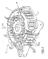
- the rear bearing 1 that appears on the figure 1 in section with the other elements of the alternator is shown only in perspective on the figure 2 .
- This bearing has a generally hollow shape of revolution, while including two protuberances 25 and 26 which extend radially relative to the skirt 18 and which form two fastening tabs on a fixed part of the vehicle.
- the discharge slots 17 each comprise an axial portion 17A extending in the axial direction of the machine, and a radial portion 17B extending in a peripheral annular zone of the front face 8 of the rear bearing 1.
- stator buns 20 which run along the internal surface of the skirt 18, in particular at the discharge slits 17.
- the cooling air current lines are represented symbolically by the arrows F, F 'and T on the figure 1 .
- the radial portions 17B of the discharge slots 17 which are provided to allow the manufacture by molding of the bearing are detrimental to cooling. Indeed, they generate on the one hand vortices T in the flow of the discharge air which introduces pressure drops, and on the other hand, the forced air F 'is sucked through the radial openings 15 and / or louvers 13 of the hood with fresh air.
- This solution is adapted to an alternator mounted in a complementary housing of the powertrain of the vehicle, the outer edge of the ring bearing against the mounting clearance close against this housing to form a watertight partition which separates the discharge slots of the gills of the cover.
- This ring is shaped to spur the shape of the corresponding housing in the engine space where the alternator is mounted.
- the object of the invention is therefore to improve the cooling of an alternator comprising a bearing such as the rear bearing described above, without modifying the design of this bearing.
- the object of the invention is also to provide a solution to improve the cooling of the alternator with additional manufacturing cost and additional space the lowest possible.
- the subject of the invention is a rotating electrical machine, such as a motor vehicle alternator, this machine including a device for forced circulation of a cooling fluid, a stator and a rotor which are housed in a housing.
- a rotating electrical machine such as a motor vehicle alternator
- this machine including a device for forced circulation of a cooling fluid, a stator and a rotor which are housed in a housing.
- a front bearing and a rear bearing at least one of the two bearings comprising a front face and a substantially cylindrical skirt, this skirt having an open end and an end closed by the front face, openings of intake of fresh air made in the front face, hot air discharge slots, each discharge slot comprising an axial portion extending in the skirt and a radial portion extending in a peripheral zone of the end face,
- the machine comprising at least one closure means which closes at least a radial portion of the slot.
- the closure means comprises at least one extension, each extension having a complementary shape of a corresponding slot radial portion to engage in a corresponding slot radial portion.
- each extension has a thickness sufficient to fill the radial slot portion that it closes over the entire thickness of this radial slot portion, so as to constitute an inner surface of the bearing which is continuous in the closed area.
- At least one extension of the closure means constitutes a lug adapted to snap into a corresponding slot radial portion to both seal this radial slot portion and ensure the fixing of the closure means to the bearing.
- the sealing means is formed by a ring fixed to the front face of the bearing.
- the machine comprises a cover covering the bearing, and the sealing means is part of the cover that extends.
- the machine comprises a plurality of closure means, each closure means forming a plug which locks in a radial slot portion snap.
- the sealing means is made of plastic.
- the closure means is fixed to the bearing by tie rods or screws.
- the invention also relates to a closure means for a rotary electrical machine, such as a motor vehicle alternator, this machine including a forced circulation device for a cooling fluid, a stator and a rotor which are housed in a housing.
- crankcase with a front bearing and a bearing rear, at least one of the two bearings comprising a front face and a substantially cylindrical skirt, this skirt having an open end and an end closed by the end face, fresh air intake openings made in the front face, hot air discharge slots, each discharge slot comprising an axial portion extending into the skirt and a radial portion extending into a peripheral zone of the end face.
- the closure means comprises at least one extension intended to plug at least one radial portion of slot each extension having a shape complementary to a radial portion of the corresponding discharge slot of the bearing to engage in a part. corresponding slot radial.
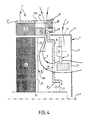
- the rotating electrical machine comprises at least one closure means 27 which minus a radial portion 17B of slot.
- the radial portions 17B of the discharge slots 17 in the front face 8 of the rear bearing 1 are plugged by a closure means 27.
- the radial portions 17B of the slots 17 do not evacuate. air, which avoids generating vortices T, and prevents hot air F to recirculate in the alternator.
- the radial portions 17B can be plugged either by a plurality of independent closure means 27 fixed to the rear bearing 1, or by a single closure means 27 possibly forming part of the cover 11 here made of plastic.
- the closure means 27 has a generally annular shape and forms part of the cover 11. It constitutes a generally flat annular surface perpendicular to the skirt 14 of the cover 11 which it extends radially at the level of the circular edge of the free end of this cylindrical wall.
- This closure means 27 comprises several extensions marked by 28 in the figures, which engage within the radial portions of corresponding slots 17B that they close.
- these extensions 28 have a sufficient thickness to fill the radial portion 17B slot they close over its entire depth.
- the extensions thus fill the radial portions of the slots 17B so as to obtain an inner surface of the rear bearing 1 which is also continuous at the parts closed by the extensions 28.
- This internal surface is thus able to direct the flow of air evacuated by the fan 16, in a direction as radial as possible to prevent this air can be sucked by the openings 13, 15, and this, introducing the least amount of air. possible pressure drop, thanks to the suppression of turbulence, more precisely of swirling air backs.
- the inner surface of the rear bearing with the parts closed by the extensions 28 is conical so as to direct the flow of air evacuated by the fan 16 towards the front of the alternator, that is to say in one direction substantially opposed to the gills 13, 15.
- the extensions 28 may advantageously have complementary shapes of the internal shape of the ends of slots 17B that they close so as to lock in it by snapping to also ensure the fixing of the closure means 27 and the cover 11 on the rear bearing 1.
- one or more extensions 28 of the closure means 27 constitute both a shutter plugging a radial portion 17B of slot 17, and a pin for fixing the closure means 27 and the cover to the rear bearing 1.
- each slot radial portion 17B can be closed by a shutter means of its own, each closure means then being a plug which locks in this radial slot portion 17B due to its complementary shape.
- the closure means 27 is formed by an independent piece that can be made of plastic, which is fixed to the rear bearing 1 by one or more screws marked by 29. These screws 29 pass through the closure means 27 which generally has a annular shape and which surrounds a circular edge of the cover 11, being screwed into corresponding threads formed in the end face 8 of the rear bearing 1.
- the closure means 27 may be fixed to the rear bearing 1 by any other appropriate means, for example by tie rods, by gluing or by attachment to another element of the alternator such as the cover 11.
- the closure means 27 comprises extensions 28 having complementary shapes of the inside of the radial portions 17B of the slots 17 to direct the flow of hot air expelled by the fan 16 in a direction inscribed in a radial plane in order to reduce as much as possible the risk of looping back this hot air and swirls.
- the invention makes it possible to improve the cooling of an alternator without having to modify the shape or the molding technique of the rear bearing 1 that it comprises.
- the sealing means 27 is advantageously made of molded plastic, so that its manufacturing cost per se is very low. It can also be realized in the form of an independent insert intended to be fixed to the rear bearing 1, so that it can be adapted to an existing rear bearing, without it being necessary to modify the rear bearing. 1, or the cover 11 of this bearing.
- the invention is applied to an alternator rear bearing, on which is mounted the recovery device 9 which is the hottest part of the alternator.
- the invention also applies to the front bearing of an alternator that does not necessarily support a recovery device, but which can nevertheless have a very similar shape, and whose cooling must also be optimal.
- the closure means may be part of a baffle having the shape of the cover 11 then lacking the bottom 17.
- the invention also applies to the case of an alternator in which one of the bearings is cooled by water, and the other by air.
- the alternator housing may have more than two parts, for example three parts, namely a front bearing, a rear bearing and an intermediate portion implanted between the two bearings and fixed thereto, for example by screwing.
- the invention also applies to rotating electrical machines generally provided with a current converter, whether it be a rectifier as in the embodiments presented above, or a device of the type chopper or inverter, which corresponds for example to the case of an alternator-starter which also applies the invention.
- a current converter whether it be a rectifier as in the embodiments presented above, or a device of the type chopper or inverter, which corresponds for example to the case of an alternator-starter which also applies the invention.
- some of the slots are provided with a closure means which closes at least a radial portion 17B of slot 17.
Landscapes
- Engineering & Computer Science (AREA)
- Power Engineering (AREA)
- Motor Or Generator Cooling System (AREA)
- Motor Or Generator Frames (AREA)
- Synchronous Machinery (AREA)
Claims (9)
- Drehende elektrische Maschine, wie eine Lichtmaschine für ein Kraftfahrzeug, wobei diese Maschine eine Vorrichtung (16) zur Zwangszirkulation eines Kühlmittels, einen Stator (3) und einen Rotor (4) umfasst, die in einem Gehäuse aufgenommen sind, das mit einem vorderen Lager und einem hinteren Lager (1) versehen ist, wobei mindestens eines der beiden Lager (1) eine vordere Fläche (8) und eine im Wesentlichen zylindrische Schürze (18) umfasst, wobei diese Schürze (18) ein offenes Ende und ein durch die vordere Fläche (8) geschlossenes Ende, in der vorderen Fläche (8) ausgebildete Öffnungen (19) zum Einlass von Frischluft, Schlitze (17) zum Abführen von Warmluft aufweist, wobei jeder Abführschlitz einen axialen Teil (17A), der sich in der Schürze (18) erstreckt, umfasst, wobei die Maschine einen radialen Teil (17B), der sich in einer Umfangszone der Stirnseite (8) erstreckt, und mindestens ein Verschlussmittel (27), das mindestens einen radialen Teil (17B) des Schlitzes (17) versperrt, umfasst, dadurch gekennzeichnet, dass das Verschlussmittel (27) mindestens eine Erweiterung (28) umfasst, wobei jede Erweiterung zum Eingreifen in einen entsprechenden radialen Teil (17B) des Schlitzes (17) eine zu einem entsprechenden radialen Teil (17B) des Schlitzes (17) komplementäre Form aufweist.
- Maschine nach Anspruch 1, dadurch gekennzeichnet, dass jede Erweiterung (28) eine Dicke aufweist, die ausreicht, den radialen Teil des Schlitzes (17B) so zu überdecken, dass sie die gesamte Dicke dieses radialen Teils des Schlitzes (17B) verschließt, um eine Innenfläche des Lagers (1) herzustellen, die in den verschlossenen Bereich weiterführt.
- Maschine nach Anspruch 1 oder 2, dadurch gekennzeichnet, dass mindestens eine Erweiterung (28) des Verschlussmittels eine Nase bildet, die in einen entsprechenden radialen Teil (17B) des Schlitzes (17) einrasten kann, um gleichzeitig diesen radialen Teil (17B) des Schlitzes zu verschließen und die Befestigung des Verschlussmittels (27) am Lager (1) zu gewährleisten.
- Maschine nach einem der vorhergehenden Ansprüche, dadurch gekennzeichnet, dass das Verschlussmittel (27) durch einen an der Stirnseite (8) des Lagers (1) befestigten Ring gebildet wird.
- Maschine nach einem der vorhergehenden Ansprüche, die einen Deckel (11) umfasst, der das Lager (1) bedeckt, dadurch gekennzeichnet, dass das Verschlussmittel (27) Teil des Deckels (11) ist, den es verlängert.
- Maschine nach einem der vorhergehenden Ansprüche, dadurch gekennzeichnet, dass sie mehrere Verschlussmittel (27) umfasst, wobei jedes Verschlussmittel einen Stopfen bildet, der sich in einem radialen Teil (17B) des Schlitzes durch Einrasten festklemmt.
- Maschine nach einem der vorhergehenden Ansprüche, dadurch gekennzeichnet, dass das Verschlussmittel (27) aus Kunststoff hergestellt ist.
- Maschine nach einem der vorhergehenden Ansprüche, dadurch gekennzeichnet, dass das Verschlussmittel (27) durch Zuganker oder Schrauben (29) am Lager (1) befestigt ist.
- Verschlussmittel für eine drehende elektrische Maschine, wie eine Lichtmaschine für ein Kraftfahrzeug, wobei diese Maschine eine Vorrichtung (16) zur Zwangszirkulation eines Kühlmittels, einen Stator (3) und einen Rotor (4) umfasst, die in einem Gehäuse aufgenommen sind, das mit einem vorderen Lager und einem hinteren Lager (1) versehen ist, wobei mindestens eines der beiden Lager (1) eine vordere Fläche (8) und eine im Wesentlichen zylindrische Schürze (18) umfasst, wobei diese Schürze (18) ein offenes Ende und ein durch die vordere Fläche (8) geschlossenes Ende, in der vorderen Fläche (8) ausgebildete Öffnungen (19) zum Einlass von Frischluft, Schlitze (17) zum Abführen von Warmluft aufweist, wobei jeder Abführschlitz einen axialen Teil (17A), der sich in der Schürze (18) erstreckt, und einen radialen Teil (17B), der sich in einer Umfangszone der Stirnseite (8) erstreckt, umfasst, dadurch gekennzeichnet, dass es mindestens eine Erweiterung (28), die zum Versperren mindestens eines radialen Teils (17B) des Schlitzes (17) vorgesehen ist, umfasst, wobei jede Erweiterung zum Eingriff in einen entsprechenden radialen Teil (17B) des Schlitzes (17) eine zu einem entsprechenden radialen Teil (17B) des Schlitzes (17) komplementäre Form aufweist.
Applications Claiming Priority (2)
| Application Number | Priority Date | Filing Date | Title |
|---|---|---|---|
| FR0404662A FR2870054B1 (fr) | 2004-04-30 | 2004-04-30 | Alternateur refroidi par air comprenant un moyen d'obturation fermant des extremites de fentes de refoulement de l'air de refroidissement |
| PCT/FR2005/001039 WO2005117241A1 (fr) | 2004-04-30 | 2005-04-27 | Alternateur pour vehicule automobile |
Publications (2)
| Publication Number | Publication Date |
|---|---|
| EP1741176A1 EP1741176A1 (de) | 2007-01-10 |
| EP1741176B1 true EP1741176B1 (de) | 2013-04-03 |
Family
ID=34944687
Family Applications (1)
| Application Number | Title | Priority Date | Filing Date |
|---|---|---|---|
| EP05767468A Expired - Lifetime EP1741176B1 (de) | 2004-04-30 | 2005-04-27 | Generator für ein fahrzeug |
Country Status (5)
| Country | Link |
|---|---|
| EP (1) | EP1741176B1 (de) |
| JP (1) | JP4755177B2 (de) |
| CN (1) | CN1930759B (de) |
| FR (1) | FR2870054B1 (de) |
| WO (1) | WO2005117241A1 (de) |
Families Citing this family (6)
| Publication number | Priority date | Publication date | Assignee | Title |
|---|---|---|---|---|
| FR2998732B1 (fr) * | 2012-11-28 | 2015-01-02 | Valeo Equip Electr Moteur | Capot d'une machine electrique tournante pour recouvrir une face frontale |
| CN105703540B (zh) * | 2014-11-24 | 2020-09-01 | 舍弗勒技术有限两合公司 | 一种液冷型轮毂电机及机动车 |
| FR3062531B1 (fr) * | 2017-01-27 | 2019-06-07 | Valeo Equipements Electriques Moteur | Machine electrique tournante munie d'un obturateur limitant un rebouclage d'air chaud |
| FR3066658B1 (fr) * | 2017-05-18 | 2020-01-10 | Valeo Equipements Electriques Moteur | Machine electrique tournante munie d'un palier ayant au moins une portion de serrage |
| JP7006697B2 (ja) * | 2017-09-29 | 2022-01-24 | 日本電産株式会社 | モータ |
| FR3079979B1 (fr) * | 2018-04-10 | 2020-03-06 | Valeo Equipements Electriques Moteur | Machine electrique tournante a refroidissement ameliore |
Family Cites Families (4)
| Publication number | Priority date | Publication date | Assignee | Title |
|---|---|---|---|---|
| JP3514319B2 (ja) * | 1993-07-26 | 2004-03-31 | 株式会社デンソー | 回転電機 |
| FR2733642B1 (fr) | 1995-04-26 | 1997-06-06 | Valeo Equip Electr Moteur | Alternateur pour vehicule automobile muni de moyens de cloisonnement externes pour eviter un bouclage du circuit d'air de refroidissement |
| WO1999041822A1 (en) * | 1998-02-13 | 1999-08-19 | Hitachi, Ltd. | Open type electric motor for driving vehicle |
| JP3842001B2 (ja) * | 2000-02-16 | 2006-11-08 | 三菱電機株式会社 | 車両用交流発電機 |
-
2004
- 2004-04-30 FR FR0404662A patent/FR2870054B1/fr not_active Expired - Fee Related
-
2005
- 2005-04-27 JP JP2007510075A patent/JP4755177B2/ja not_active Expired - Fee Related
- 2005-04-27 WO PCT/FR2005/001039 patent/WO2005117241A1/fr not_active Ceased
- 2005-04-27 CN CN2005800070465A patent/CN1930759B/zh not_active Expired - Lifetime
- 2005-04-27 EP EP05767468A patent/EP1741176B1/de not_active Expired - Lifetime
Also Published As
| Publication number | Publication date |
|---|---|
| WO2005117241A1 (fr) | 2005-12-08 |
| EP1741176A1 (de) | 2007-01-10 |
| JP2007535889A (ja) | 2007-12-06 |
| CN1930759A (zh) | 2007-03-14 |
| FR2870054B1 (fr) | 2006-07-21 |
| CN1930759B (zh) | 2011-03-30 |
| JP4755177B2 (ja) | 2011-08-24 |
| FR2870054A1 (fr) | 2005-11-11 |
Similar Documents
| Publication | Publication Date | Title |
|---|---|---|
| EP0886366B1 (de) | Wechselstromgenrator mit verbesserten Mitteln zur Kühlung, insbesondere für ein Kraftfahrzeug | |
| FR2923098A1 (fr) | Ensemble palier-capot de machine electrique tournante et machine electrique tournante comportant un tel ensemble. | |
| EP2091136A1 (de) | Lagervorrichtung einer elektrischen Maschine und rotierende elektrische Maschine, die eine solche Lagervorrichtung umfasst | |
| EP1741176B1 (de) | Generator für ein fahrzeug | |
| EP3163091B1 (de) | Motoraufhängungsanordnung und entsprechende anlage zum heizen, belüften und/oder klimatisieren für kraftfahrzeug | |
| FR2853365A1 (fr) | Dispositif de ventilation | |
| FR3064540B1 (fr) | Support pour dispositif de ventilation, dispositif de ventilation et module de refroidissement correspondants | |
| FR2811156A1 (fr) | Ventilateur pour machine electrique tournante, notamment pour alternateur de vehicule automobile | |
| EP4314563B1 (de) | Kühlmodul für ein elektro- oder hybridkraftfahrzeug mit einer tangentialflussturbomaschine | |
| FR3069980B1 (fr) | Machine electrique tournante munie d'un deflecteur de liquide | |
| FR2998732A1 (fr) | Capot d'une machine electrique tournante pour recouvrir une face frontale | |
| WO2022043586A1 (fr) | Module de refroidissement pour véhicule automobile électrique à turbomachine tangentielle | |
| WO2017089670A1 (fr) | Machine électrique tournante de véhicule automobile | |
| FR2780572A1 (fr) | Alternateur pour vehicule avec circuit de refroidissement du carter par liquide | |
| FR3077344A1 (fr) | Helice de ventilateur pour vehicule automobile | |
| FR2858884A1 (fr) | Dispsositif de refroidissement d'un alternateur avec guide d'air | |
| FR3132809A1 (fr) | Rotor pour une machine électrique tournante | |
| WO2021180489A1 (fr) | Flasque plastique muni de murets de renfort pour une machine electrique tournante | |
| FR3075506B1 (fr) | Ensemble comprenant un carter de machine electrique tournante | |
| WO2024235889A1 (fr) | Guide d'air et module de refroidissement pour véhicule automobile | |
| FR3038795A1 (fr) | Machine electrique tournante a refroidissement optimise | |
| FR3089364A1 (fr) | Machine électrique tournante comprenant un dispositif de refroidissement | |
| FR3098051A1 (fr) | Carter pour machine électrique tournante comprenant un palier plastique | |
| WO2025195920A1 (fr) | Moteur électrique notamment configuré pour équiper une pompe | |
| FR2864368A1 (fr) | Dispositif de renforcement de la ventilation d'une machine electrique et machine electrique comportant un tel dispositif |
Legal Events
| Date | Code | Title | Description |
|---|---|---|---|
| PUAI | Public reference made under article 153(3) epc to a published international application that has entered the european phase |
Free format text: ORIGINAL CODE: 0009012 |
|
| 17P | Request for examination filed |
Effective date: 20061018 |
|
| AK | Designated contracting states |
Kind code of ref document: A1 Designated state(s): AT BE BG CH CY CZ DE DK EE ES FI FR GB GR HU IE IS IT LI LT LU MC NL PL PT RO SE SI SK TR |
|
| DAX | Request for extension of the european patent (deleted) | ||
| 17Q | First examination report despatched |
Effective date: 20090330 |
|
| GRAP | Despatch of communication of intention to grant a patent |
Free format text: ORIGINAL CODE: EPIDOSNIGR1 |
|
| GRAS | Grant fee paid |
Free format text: ORIGINAL CODE: EPIDOSNIGR3 |
|
| GRAA | (expected) grant |
Free format text: ORIGINAL CODE: 0009210 |
|
| AK | Designated contracting states |
Kind code of ref document: B1 Designated state(s): AT BE BG CH CY CZ DE DK EE ES FI FR GB GR HU IE IS IT LI LT LU MC NL PL PT RO SE SI SK TR |
|
| REG | Reference to a national code |
Ref country code: GB Ref legal event code: FG4D Free format text: NOT ENGLISH |
|
| REG | Reference to a national code |
Ref country code: CH Ref legal event code: EP Ref country code: AT Ref legal event code: REF Ref document number: 605249 Country of ref document: AT Kind code of ref document: T Effective date: 20130415 |
|
| REG | Reference to a national code |
Ref country code: IE Ref legal event code: FG4D Free format text: LANGUAGE OF EP DOCUMENT: FRENCH |
|
| REG | Reference to a national code |
Ref country code: DE Ref legal event code: R096 Ref document number: 602005038895 Country of ref document: DE Effective date: 20130606 |
|
| REG | Reference to a national code |
Ref country code: AT Ref legal event code: MK05 Ref document number: 605249 Country of ref document: AT Kind code of ref document: T Effective date: 20130403 |
|
| PG25 | Lapsed in a contracting state [announced via postgrant information from national office to epo] |
Ref country code: SI Free format text: LAPSE BECAUSE OF FAILURE TO SUBMIT A TRANSLATION OF THE DESCRIPTION OR TO PAY THE FEE WITHIN THE PRESCRIBED TIME-LIMIT Effective date: 20130403 |
|
| REG | Reference to a national code |
Ref country code: NL Ref legal event code: VDEP Effective date: 20130403 |
|
| REG | Reference to a national code |
Ref country code: LT Ref legal event code: MG4D |
|
| BERE | Be: lapsed |
Owner name: VALEO EQUIPEMENTS ELECTRIQUES MOTEUR Effective date: 20130430 |
|
| PG25 | Lapsed in a contracting state [announced via postgrant information from national office to epo] |
Ref country code: FI Free format text: LAPSE BECAUSE OF FAILURE TO SUBMIT A TRANSLATION OF THE DESCRIPTION OR TO PAY THE FEE WITHIN THE PRESCRIBED TIME-LIMIT Effective date: 20130403 Ref country code: IS Free format text: LAPSE BECAUSE OF FAILURE TO SUBMIT A TRANSLATION OF THE DESCRIPTION OR TO PAY THE FEE WITHIN THE PRESCRIBED TIME-LIMIT Effective date: 20130803 Ref country code: SE Free format text: LAPSE BECAUSE OF FAILURE TO SUBMIT A TRANSLATION OF THE DESCRIPTION OR TO PAY THE FEE WITHIN THE PRESCRIBED TIME-LIMIT Effective date: 20130403 Ref country code: AT Free format text: LAPSE BECAUSE OF FAILURE TO SUBMIT A TRANSLATION OF THE DESCRIPTION OR TO PAY THE FEE WITHIN THE PRESCRIBED TIME-LIMIT Effective date: 20130403 Ref country code: GR Free format text: LAPSE BECAUSE OF FAILURE TO SUBMIT A TRANSLATION OF THE DESCRIPTION OR TO PAY THE FEE WITHIN THE PRESCRIBED TIME-LIMIT Effective date: 20130704 Ref country code: PT Free format text: LAPSE BECAUSE OF FAILURE TO SUBMIT A TRANSLATION OF THE DESCRIPTION OR TO PAY THE FEE WITHIN THE PRESCRIBED TIME-LIMIT Effective date: 20130805 Ref country code: LT Free format text: LAPSE BECAUSE OF FAILURE TO SUBMIT A TRANSLATION OF THE DESCRIPTION OR TO PAY THE FEE WITHIN THE PRESCRIBED TIME-LIMIT Effective date: 20130403 Ref country code: NL Free format text: LAPSE BECAUSE OF FAILURE TO SUBMIT A TRANSLATION OF THE DESCRIPTION OR TO PAY THE FEE WITHIN THE PRESCRIBED TIME-LIMIT Effective date: 20130403 Ref country code: ES Free format text: LAPSE BECAUSE OF FAILURE TO SUBMIT A TRANSLATION OF THE DESCRIPTION OR TO PAY THE FEE WITHIN THE PRESCRIBED TIME-LIMIT Effective date: 20130714 |
|
| PG25 | Lapsed in a contracting state [announced via postgrant information from national office to epo] |
Ref country code: PL Free format text: LAPSE BECAUSE OF FAILURE TO SUBMIT A TRANSLATION OF THE DESCRIPTION OR TO PAY THE FEE WITHIN THE PRESCRIBED TIME-LIMIT Effective date: 20130403 Ref country code: BG Free format text: LAPSE BECAUSE OF FAILURE TO SUBMIT A TRANSLATION OF THE DESCRIPTION OR TO PAY THE FEE WITHIN THE PRESCRIBED TIME-LIMIT Effective date: 20130703 Ref country code: CY Free format text: LAPSE BECAUSE OF FAILURE TO SUBMIT A TRANSLATION OF THE DESCRIPTION OR TO PAY THE FEE WITHIN THE PRESCRIBED TIME-LIMIT Effective date: 20130403 |
|
| REG | Reference to a national code |
Ref country code: CH Ref legal event code: PL |
|
| REG | Reference to a national code |
Ref country code: IE Ref legal event code: MM4A |
|
| PG25 | Lapsed in a contracting state [announced via postgrant information from national office to epo] |
Ref country code: EE Free format text: LAPSE BECAUSE OF FAILURE TO SUBMIT A TRANSLATION OF THE DESCRIPTION OR TO PAY THE FEE WITHIN THE PRESCRIBED TIME-LIMIT Effective date: 20130403 Ref country code: MC Free format text: LAPSE BECAUSE OF FAILURE TO SUBMIT A TRANSLATION OF THE DESCRIPTION OR TO PAY THE FEE WITHIN THE PRESCRIBED TIME-LIMIT Effective date: 20130403 Ref country code: CH Free format text: LAPSE BECAUSE OF NON-PAYMENT OF DUE FEES Effective date: 20130430 Ref country code: LI Free format text: LAPSE BECAUSE OF NON-PAYMENT OF DUE FEES Effective date: 20130430 Ref country code: DK Free format text: LAPSE BECAUSE OF FAILURE TO SUBMIT A TRANSLATION OF THE DESCRIPTION OR TO PAY THE FEE WITHIN THE PRESCRIBED TIME-LIMIT Effective date: 20130403 Ref country code: CZ Free format text: LAPSE BECAUSE OF FAILURE TO SUBMIT A TRANSLATION OF THE DESCRIPTION OR TO PAY THE FEE WITHIN THE PRESCRIBED TIME-LIMIT Effective date: 20130403 Ref country code: BE Free format text: LAPSE BECAUSE OF NON-PAYMENT OF DUE FEES Effective date: 20130430 Ref country code: SK Free format text: LAPSE BECAUSE OF FAILURE TO SUBMIT A TRANSLATION OF THE DESCRIPTION OR TO PAY THE FEE WITHIN THE PRESCRIBED TIME-LIMIT Effective date: 20130403 |
|
| PLBE | No opposition filed within time limit |
Free format text: ORIGINAL CODE: 0009261 |
|
| STAA | Information on the status of an ep patent application or granted ep patent |
Free format text: STATUS: NO OPPOSITION FILED WITHIN TIME LIMIT |
|
| PG25 | Lapsed in a contracting state [announced via postgrant information from national office to epo] |
Ref country code: RO Free format text: LAPSE BECAUSE OF FAILURE TO SUBMIT A TRANSLATION OF THE DESCRIPTION OR TO PAY THE FEE WITHIN THE PRESCRIBED TIME-LIMIT Effective date: 20130403 Ref country code: IT Free format text: LAPSE BECAUSE OF FAILURE TO SUBMIT A TRANSLATION OF THE DESCRIPTION OR TO PAY THE FEE WITHIN THE PRESCRIBED TIME-LIMIT Effective date: 20130403 |
|
| 26N | No opposition filed |
Effective date: 20140106 |
|
| GBPC | Gb: european patent ceased through non-payment of renewal fee |
Effective date: 20130703 |
|
| REG | Reference to a national code |
Ref country code: DE Ref legal event code: R097 Ref document number: 602005038895 Country of ref document: DE Effective date: 20140106 |
|
| PG25 | Lapsed in a contracting state [announced via postgrant information from national office to epo] |
Ref country code: IE Free format text: LAPSE BECAUSE OF NON-PAYMENT OF DUE FEES Effective date: 20130427 Ref country code: GB Free format text: LAPSE BECAUSE OF NON-PAYMENT OF DUE FEES Effective date: 20130703 |
|
| PG25 | Lapsed in a contracting state [announced via postgrant information from national office to epo] |
Ref country code: TR Free format text: LAPSE BECAUSE OF FAILURE TO SUBMIT A TRANSLATION OF THE DESCRIPTION OR TO PAY THE FEE WITHIN THE PRESCRIBED TIME-LIMIT Effective date: 20130403 |
|
| PG25 | Lapsed in a contracting state [announced via postgrant information from national office to epo] |
Ref country code: HU Free format text: LAPSE BECAUSE OF FAILURE TO SUBMIT A TRANSLATION OF THE DESCRIPTION OR TO PAY THE FEE WITHIN THE PRESCRIBED TIME-LIMIT; INVALID AB INITIO Effective date: 20050427 Ref country code: LU Free format text: LAPSE BECAUSE OF NON-PAYMENT OF DUE FEES Effective date: 20130427 |
|
| REG | Reference to a national code |
Ref country code: FR Ref legal event code: PLFP Year of fee payment: 12 |
|
| REG | Reference to a national code |
Ref country code: FR Ref legal event code: PLFP Year of fee payment: 13 |
|
| REG | Reference to a national code |
Ref country code: FR Ref legal event code: PLFP Year of fee payment: 14 |
|
| P01 | Opt-out of the competence of the unified patent court (upc) registered |
Effective date: 20230528 |
|
| PGFP | Annual fee paid to national office [announced via postgrant information from national office to epo] |
Ref country code: DE Payment date: 20240409 Year of fee payment: 20 |
|
| PGFP | Annual fee paid to national office [announced via postgrant information from national office to epo] |
Ref country code: FR Payment date: 20240423 Year of fee payment: 20 |
|
| REG | Reference to a national code |
Ref country code: DE Ref legal event code: R071 Ref document number: 602005038895 Country of ref document: DE |