EP1741340B1 - Dispositif et méthode de découpe de carcasse en connection avec le découpage longitudinal des carcasses - Google Patents
Dispositif et méthode de découpe de carcasse en connection avec le découpage longitudinal des carcasses Download PDFInfo
- Publication number
- EP1741340B1 EP1741340B1 EP06388048.8A EP06388048A EP1741340B1 EP 1741340 B1 EP1741340 B1 EP 1741340B1 EP 06388048 A EP06388048 A EP 06388048A EP 1741340 B1 EP1741340 B1 EP 1741340B1
- Authority
- EP
- European Patent Office
- Prior art keywords
- knife
- meat
- abutment
- ribs
- wing
- Prior art date
- Legal status (The legal status is an assumption and is not a legal conclusion. Google has not performed a legal analysis and makes no representation as to the accuracy of the status listed.)
- Active
Links
Images


Classifications
-
- A—HUMAN NECESSITIES
- A22—BUTCHERING; MEAT TREATMENT; PROCESSING POULTRY OR FISH
- A22C—PROCESSING MEAT, POULTRY, OR FISH
- A22C17/00—Other devices for processing meat or bones
- A22C17/004—Devices for deboning meat
- A22C17/0046—Devices for deboning meat specially adapted for meat containing ribs
Definitions
- the present invention relates to an apparatus for and a method according to the preamble of claims 1 and 13, respectively.
- Middles from pig carcases are usually separated into a loin part and a belly part by being given one or more longitudinal cuts extending at a distance from the spine.
- the separation may be performed by a cut going through both the ribs and the meat, but in certain productions it may be advantageous to separate the middles by two cuts extending differently in the meat part and the rib part. This may be effected by the operator first cutting through the ribs so as to separate them in the desired way. Then the ribs are cut away, and finally the operator separates the ribless meat to provide the desired cuts.
- the process is complicated and a physical strain on the operator, it is only used when substantial financial advantages are obtained thereby.
- wing knife does not allow complete automation of the separation of the middle. For one reason, there are only ribs in part of the middle, and for another reason the ribs curve differently in different parts of the middle. This may, for example, result in meat being left on the undersides of the ribs or the knife cutting into the ribs. Furthermore, the wing knife does not solve the particular problems of accurately cutting free the last rib, which is located approximately halfway down the middle. Often, this rib will have meat left on it that should have been cut free together with the meat part.
- EP-A-985 348 upon which the preamble of claim 1 is based, discloses an apparatus for longitudinal cutting middles, which are conveyed with their rib sides facing upwards and their rind sides facing downwards.
- the apparatus may i.a. separate the middles into a loin part and a belly part by cuts extending through meat and ribs, but the apparatus may also perform cuts that extend through rind and meat without cutting the ribs.
- a non-rotating knife having a shape like a butchers knife, though a rotating circular knife is shown in the specific embodiments.
- the middles are conveyed by means of a conveyor of the art disclosed in EP-A-1 059 037 , which holds the middles by the spine.
- This second embodiment comprises a resiliently suspended support for the rind side, and it may comprise another support, not shown and not described in any detail, for supporting the rib side of the middle during cutting.
- this object is obtained in that the apparatus, wherein the abutment is movable in a direction downwards towards and away from the meat knife, and that the meat knife is movable in a direction upwards towards the abutment with a force smaller than the force whereby the abutment can be moved downwards.
- the cut may go all the way up to the underside of the ribs as the abutment presses on the upper side of the ribs towards the meat knife and it is possible to exercise a controlled pressure on the middle from both sides.
- the meat knife is adapted not to cut into the ribs.
- This may be provided in various ways, for example by the meat knife comprising a control member located underneath the abutment and having a guide surface that may be made to make contact with the underside of the ribs of the middle in/at the cut in the middle made by the meat knife. This makes a very accurate control of the abutment and/or meat knife superfluous.
- the control member may comprise a wing knife with a first knife part arranged in a plane of the meat knife and a second knife part projecting to one side from the upper edge of the first knife part and possibly a third knife part projecting to the other side.
- a very compact structure is thus achieved as control and undercutting of the ribs may be performed by one and the same device. It is particularly preferred that the second and/or the third knife part of the wing knife may be moved to a plane above the rest of the meat knife so that the upper surface(s) of the knife part(s) serve(s) as guide surface(s).
- the combined use of a wing knife and an abutment also results in close undercutting of the ribs because the middle cannot rise substantially relative to the wing knife, and at the cutting in the flank part of the middle, which has no ribs, the abutment prevents the soft meat from moving before the meat knife.
- the part of the meat knife that performs the cut from the rind and up to the ribs is not moved all the way up to the underside of the ribs, but that the top part of the cut is instead made with the first knife part of the wing knife.
- the first knife part preferably, in a working position, has a sharp upper edge which is located at a level below the second knife part and rises in the conveying direction of the middle and/or a sharp lower edge which falls in the conveying direction of the middle.
- the apparatus comprises the meat knife in form of a cutting unit comprising a knife for performing the cut in the meat and a wing knife for undercutting, which cutting unit may be moved upwards so that the wing knife makes contact with the at least one abutment.
- Use of an aggregate unit comprising both wing knife and knife results in completely synchronised positioning thereof relative to the middle.
- the abutment may make direct contact with the wing knife so as to position the cutting unit at the start of the cutting or it may make contact with the rib side to keep the middle in contact with the wing knife, the upper surface of which is guided along the underside of the ribs.
- the movement of the abutment towards the cutting unit or the meat knife is preferably limited by a stop.
- the abutment and the meat knife are preferably spring loaded towards each other during operation so that they may adjust to each other and the ribs during cutting. This also contributes to the close undercutting as the wing knife will all the time be moved as closely against the undersides of the ribs as possible.
- the second and/or third knife part of the wing knife is/are preferably mounted so that it can tilt about an axis being substantially parallel with the direction of the relative movement between the meat knife and the retention device. In this way, the angling of the knife blade may adjust to the curvature of the current rib.
- the apparatus therefore preferably comprises two abutments which are moveable independently of each other between an inactive position and at least one active position.
- the first abutment is used during the preliminary part of the cutting, while the second abutment is used during the subsequent part.
- Preferably, only one of the abutments is active at a time, but situations may occur in which it will be an advantage that both abutments are active at the same time.
- the abutments are swingable arms, the first abutment being located above the cut of the meat knife and the second abutment preferably is located in a position on the far side of the first abutment as seen from the retention device.
- the cutting unit may be pressed down by an abutment arranged centrally above the cutting unit, which results in the smallest possible load on the cutting unit.
- the displaced location of the second abutment ensures that the knives cannot make contact with the abutment during the cutting of the flank part.
- the two abutments may function separately or at the same time, but in one embodiment the first abutment is moved to its inactive position before the cutting of the flank part is started.
- the wing knife If the wing knife is only used in the part of the middle that contains ribs, and not in the flank part, it can preferably be moved between two or more different positions, at least one of these positions being a working position and one of these positions being an inactive position. At the transition between the rib part and the flank part, the wing knife may then be moved from an active to an inactive position or vice versa depending on the conveying direction of the middle. By moving the wing knife between several different active positions, it is also possible to obtain adjustment to the curvature of the middle.
- the part of the meat knife which performs the cut from the rind and up to the ribs may be designed in different ways, but in a preferred embodiment it is a circular blade, and the wing knife may then be movable between its different positions by turning about the centre of the circular blade.
- the apparatus may also comprise a rib saw for cutting the ribs at a distance from the spine, which saw is arranged downstream of the meat knife.
- the transport arrangement may be of the structure described in Danish patent DK-C-173412 and the corresponding EP-A-1 059 037 .
- the apparatus according to the invention may comprise other cutting units, such as a rib top saw for cutting off the rib heads, knives for cutting along the meat-rib transitions of the spine, a knife for separating the meat part from the rib part, etc.
- other cutting units such as a rib top saw for cutting off the rib heads, knives for cutting along the meat-rib transitions of the spine, a knife for separating the meat part from the rib part, etc.
- the purpose is also obtained with a method of cutting the meat part of a middle by means of a meat knife, possibly comprising a wing knife, the middle being kept in contact with the meat knife by means of at least one abutment.
- the wing knife 11 constitutes part of a cutting unit 10, which also comprises a circular knife 15.
- the wing knife 11 and the circular knife 15 jointly perform the cut 5, the circular knife cutting most of the meat part 2, while the wing knife at its point has a first knife part in the shape of a knife blade 12 with an edge 12a which is parallel with the circular blade and takes the cut all the way up to the underside of the ribs 3.
- Wings 13, which constitute a second and a third knife part or a second and a third knife blade, perform the actual undercutting, and in the embodiment shown the wing knife performs a combined undercutting and cutting of the meat part.
- embodiments may also be contemplated in which the circular knife 15 is located higher and cuts all the way up to the underside of the ribs, while the wing knife only has cutting edges on the wings 13 parallel with the ribs.
- the middle 1 is held against the cutting unit 10 by means of at least one abutment 21 as shown in Fig. 2 .
- the abutment 21 is moved to make contact with the upper surface of the wing knife 11 and to press the cutting unit 10 20-30 mm downwards.
- This is done by means of a pneumatic cylinder (not shown), which permits the abutment to move up and down against the downward force of the cylinder in that the pneumatic cylinder in a manner known per se acts as a spring.
- the abutment hits the upper surface of the wing knife and presses the cutting unit downwards against an upward force from another pneumatic cylinder (not shown), which actuates the cutting unit upwards.
- At the maximum cylinder stroke of the pneumatic cylinder provides a stop, which takes the movement of the abutment to a halt.
- the middle is envisaged to be suspended in a conveyor not shown of the art disclosed in EP-A-1 059 037 .
- the conveyor moves the middle 1 forwards in direction A ( Fig. 2 ) whereby it hits an oblique part 24 of the abutment.
- the middle is forced downwards and gets underneath a less oblique portion 25 and finally under an end 26 of the abutment 21 where the rib side is in close contact with the abutment.
- the knife blade 12 cuts the meat part under the ribs where the circular knife 15 was unable to reach, and as the upper edge of the knife blade 12 hits the ribs, the cutting unit is pressed downwards due to the wedge effect between the abutment and the upper edge of the knife blade 12 so that the wing knife 11 can move in and cut along the underside of the ribs.
- the abutment 21 exercises pressure on the upper side of the ribs
- the cutting unit 10 exercises pressure on the underside of the ribs, which ensures that the wings 13 of the wing knife cut close to the underside and that the circular knife cuts up to a position close to the underside of the ribs.
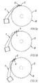
- two mutually displaced abutments 21 and 22 are used as shown in Fig. 1 .
- the abutment 21 located directly above the cutting unit 10 is used, the ribs 3 being located between the knives 11, 15 and the abutment 21. This presupposes that the conveying movement of the middle is as shown by the arrow A in Figs. 1 and 2 .
- a second abutment 22 has been provided in a position displaced from the cutting unit.
- the second abutment may be active during the entire cutting process, or a shift may be made from one abutment to the other during the cutting. Such a shift may be made at any time, while the cutting unit is positioned opposite to the ribs, but it preferably takes place as soon as the cutting unit has got a grip.
- the abutments 21 and 22 are designed as substantially identical rod-shaped arms rotatable about a common centre of rotation 23.
- abutments moved, for example, between an active and an inactive position by a movement at right angles to the plane of the middle may work just as well.
- Embodiments may also be contemplated in which the two abutments have different appearances and modes of action, or where more than two abutments are used. The latter may, for example, be advantageous if the curvature of the middle has to be taken into consideration.
- the wing knife 11 can preferably be moved between two or more active positions in which it is angled differently relative to the conveying direction A of the middle 1.
- the two positions are shown in Figs. 3a and 3b .
- the first position is used when the cut of the wing knife in the middle is to be started.
- the second position is used after the wing knife has got a distance into the middle, for example 40-60 mm.
- the transition between the two positions, which are shown in Figs. 3a and 3b may be sudden, stepwise or smooth.
- the wing knife 11 In the flank part 7 of the middle, which has no ribs, the wing knife 11 is superfluous.
- the wing knife 11 can therefore preferably be moved to a third, inactive position as shown in Fig. 3c before reaching the flank part, for example having passed 300-350 mm into the middle.
- an abutment 21 located above the cut is also used at the cutting of the flank part, and in which the wing knife then remains in an active position during the entire cutting. As there is no cutting edge on the upper surface of the wing knife, the abutment may be in direct contact with it.
- the wing knife is moved to the inactive position after passing the shortest measured rib, which is located in the transition between the rib part and the flank part.
- shortest measured rib is meant the rib that crosses the meat cut, is furthest towards the flank part and is detectable.
- a detection of the ribs is performed up stream of the apparatus described herein but while the middle is suspended in the conveyor, e.g. by means of a device as disclosed in EP-A-1 059 037 . Having knowledge of the speed of the conveyor and the distance between the detecting device and the herein described cutting device the time of passage of the shortest measured rib may be calculated.
- the wing knife in its inactive position makes its way up through the meat (which is thereby pulled down), whereby the wing 13 assumes an inactive position above the middle.
- FIG. 4a and 4b An example of the embodiment of the wing knife 11 with two wings is shown in detail in Figs. 4a and 4b .
- the two wings 13a and 13b project to respective sides of a knife blade 12, which is designed as an extension of the shaft 16 of the wing knife and, in its mounted position, is located above the circular knife 15.
- the knife blade 12 is sharp both on the upper side and the lower side so as to provide the optimum cutting of the meat part closest to the ribs and is pointed to facilitate penetration into the meat.
- the upper side inclines upwards towards the place where the wing 13 is mounted, and the lower side inclines downwards towards the actual shaft 16.
- the ribs 3 are undercut not only between the meat cut 5 and the rib cut 6, but also a distance out towards the spine 4 or the belly part.
- the undercutting cuts on the two sides of the meat cut 5 will have substantially equal extent, but embodiments with different extents may also be contemplated.
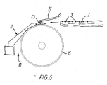
- the wings have respective shapes as seen in particular from Fig. 5b , and, in the uninfluenced position, are angled differently in relation to the shaft 16 and the upper edge of the knife blade 12 in order to achieve the optimum adaptation to the shape on the undersides of the ribs.
- the wings 13a and 13b of the wing knife are preferably hinged at the connection to the rest of the wing knife 11.
- the two wings 13a and 13b are rigidly connected, and a pin 17 is passed through a thicker middle portion 18 into a back edge of the knife blade 12 and a projection 19 so that the entire wing can turn about the pin as shown by the arrow C.
- the wings 13a and 13b may be spring-loaded so that they seek upwards towards the meat.
- Fig. 5 shows a wing knife 11 with such spring load in which the wings 13 extend relatively far upwards due to the lack of meat contact.
- a wing knife with only one wing may be used so that the undercutting is performed between the meat cut and the rib cut.
- the cut through the ribs 3 is made as the last one by means of a cutting device, not shown, typically a circular saw of a known type. Only with this cutting is the middle finally separated into two individual parts.
- the loin part can then be released from the conveyor by means of a rib-top saw or the like.
- the ribs need not be cut through directly. There may be knives that cut along the underside of the ribs so that first the meat in the flank part and then the meat in the loin part are cut free. For this purpose there may be knives upstream or downstream for cutting free the meat from the spine.
- the distances between the conveyor holding the spine and the various cutting devices are variable so that the apparatus can thereby be adjusted for the production of different cuts.
- the cutting devices can preferably be angled relative to the conveying direction to ensure that the cuts can be made at a desired angle relative to the plane of the middle. This may be advantageous, for example, if the cut must be made relatively close to the spine where the ribs curve upwards relative to the plane of the middle, as cutting at right angles is typically wanted, particularly of the ribs.
Landscapes
- Life Sciences & Earth Sciences (AREA)
- Engineering & Computer Science (AREA)
- Wood Science & Technology (AREA)
- Zoology (AREA)
- Food Science & Technology (AREA)
- Processing Of Meat And Fish (AREA)
- Meat, Egg Or Seafood Products (AREA)
- Nonmetal Cutting Devices (AREA)
Claims (20)
- Appareil pour découper la partie de viande d'une carcasse (1), comprenant un couteau à viande (10) pour réaliser une découpe s'étendant du côté de la couenne jusqu'au côté inférieur des côtes (3) et s'étendant à une certaine distance de la colonne vertébrale (4) dans le sens longitudinal de cette dernière, et un agencement de transport ayant un dispositif de retenue pour maintenir la carcasse (1) par la colonne vertébrale (4) avec le côté des côtes de la carcasse orienté dans une direction, de préférence vers le haut, et étant adapté pour fournir un mouvement relatif entre le couteau à viande (10) et le dispositif de retenue essentiellement dans le sens longitudinal de la colonne vertébrale (4), et comprenant au moins une butée (21, 22) positionnée au-dessus du couteau à viande (5), caractérisé en ce que la butée (21, 22) soit mobile dans une direction descendante vers et à distance du couteau à viande (10), et en ce que le couteau à viande (10) soit mobile dans une direction ascendante vers la butée (21, 22) avec une force inférieure à la force moyennant quoi la butée peut être déplacée vers le bas.
- Appareil selon la revendication 1, caractérisé en ce que le couteau à viande (10) comprenne un élément de commande (11) positionné en-dessous de la butée (21) et ayant une surface de guidage (18) qui peut être amenée à établir le contact avec la face inférieure des côtes (3) de la carcasse dans/au niveau de la découpe (5) dans la carcasse, effectuée par le couteau à viande (10).
- Appareil selon la revendication 2, caractérisé en ce que l'élément de commande comprenne un couteau en forme d'aile (11) avec une première partie de couteau (12) agencée dans un plan du couteau à viande (10) et une deuxième partie de couteau (13a) faisant saillie d'un côté à partir du bord supérieur de la première partie de couteau et éventuellement une troisième partie de couteau (13b) faisant saillie de l'autre côté, moyennant quoi la deuxième et/ou la troisième partie de couteau du couteau en forme d'aile peuvent/peut de préférence être déplacées dans un plan au-dessus du reste du couteau à viande (10).
- Appareil selon l'une quelconque des revendications précédentes, caractérisé en ce qu'il comprenne un vérin pneumatique pour déplacer la butée ou chaque butée (21, 22).
- Appareil selon la revendication 3, caractérisé en ce que, dans une position de travail, la première partie de couteau (12) a un bord supérieur tranchant qui est positionné à un niveau situé au-dessous de la deuxième partie de couteau (13a) et s'incline vers le haut dans la direction de transport (A) de la carcasse et/ou un bord inférieur tranchant qui s'incline vers le bas dans la direction de transport de la carcasse.
- Appareil selon l'une quelconque des revendications précédentes, caractérisé en ce qu'il comprenne un arrêt qui limite le mouvement de la butée vers le bas vers le couteau à viande.
- Appareil selon l'une quelconque des revendications précédentes, caractérisé en ce que la butée et le couteau à viande soient chargés par ressort l'un vers l'autre pendant le fonctionnement, de sorte qu'ils peuvent se régler l'un par rapport à l'autre et par rapport aux côtes pendant la découpe.
- Appareil selon l'une quelconque des revendications précédentes, caractérisé en ce qu'il comprenne deux butées (21, 22) qui soient mobiles indépendamment l'une de l'autre entre une position inactive et au moins une position active.
- Appareil selon l'une quelconque des revendications précédentes, caractérisé en ce que les butées soient des bras oscillants (21, 22), la première butée étant positionnée au-dessus de la découpe (5) du couteau à viande (10) et la seconde butée, de préférence, dans une position sur le côté éloigné de la première butée, comme observé depuis le dispositif de retenue.
- Appareil selon la revendication et l'une quelconque des revendications 4 à 9, caractérisé en ce que le couteau en forme d'aile (11) puisse être déplacé entre deux ou plus positions différentes, au moins l'une de ces positions étant une position de travail et l'une de ces positions étant une position inactive.
- Appareil selon la revendication 10, caractérisé en ce que le couteau à viande (10) comprenne une lame circulaire (15) pour réaliser la découpe allant du côté de la couenne jusqu'à la face inférieure des côtes, et en ce que le couteau en forme d'aile (11) soit mobile entre ses différentes positions en tournant autour du centre de la lame circulaire (15).
- Appareil selon la revendication ou l'une quelconque des revendications 4 à 11 lorsqu'elle dépend de la revendication 3, caractérisé en ce que la deuxième et/ou la troisième partie de couteau (13a, 13b) du couteau en forme d'aile (11) soit/soient de préférence montée(s) de sorte qu'il puisse s'incliner (C) autour d'un axe essentiellement parallèle à la direction (A) du mouvement relatif entre le couteau à viande (10) et le dispositif de retenue.
- Procédé pour découper la partie de viande d'une carcasse, moyennant quoi un couteau à viande (10) est utilisé pour effectuer une découpe (5) s'étendant depuis le côté de la couenne jusqu'au côté inférieur des côtes (3) et s'étendant à une certaine distance de la colonne vertébrale (4) et essentiellement dans la direction longitudinale de ce dernier, la carcasse étant maintenue par la colonne vertébrale avec le côté des côtes de la carcasse qui est orienté dans une direction, de préférence, vers le haut, au moyen d'un dispositif de retenue d'un agencement de transport qui fournit un mouvement (A) relatif entre le couteau à viande et le dispositif de retenue essentiellement dans le sens longitudinal de la colonne vertébrale, caractérisé en ce qu'au moins une butée (21, 22) qui est mobile dans une direction descendante vers et qui s'éloigne du couteau à viande (10) et qui est agencée au-dessus du couteau à viande, soit maintenue en contact avec le côté des côtes de la carcasse (1) pendant au moins une partie de la découpe du couteau à viande et en ce que, pendant au moins une partie du fonctionnement, le couteau à viande (10) soit forcé dans une direction ascendante vers la butée (21, 22) avec une force inférieure à la force avec laquelle la butée vient en butée contre la carcasse.
- Procédé selon la revendication 13, caractérisé en ce qu'un élément de commande (11) du couteau à viande (10) est agencé au-dessous de la butée (21) et avec une surface de guidage (18), soit amené à établir le contact avec la face inférieure des côtes de la carcasse dans/au niveau de la découpe (5) dans la carcasse, effectuée par le couteau à viande.
- Procédé selon la revendication 14, caractérisé en ce que l'élément de commande comprenne un couteau en forme d'aile (11) avec une première partie de couteau (12) agencée dans le plan du couteau à viande et une deuxième partie de couteau (13a) faisant saillie d'un côté depuis le bord supérieur de la première partie de couteau et éventuellement une troisième partie de couteau (13b) faisant saillie de l'autre côté, et en ce que, dans une position de travail, la deuxième et/ou la troisième partie de couteau du couteau en forme d'aile puissent/puisse être déplacées dans un plan au-dessus du reste du couteau à viande (10) de sorte que la (les) surface(s) supérieure(s) de la (des) partie(s) de couteau sert (servent) de surface(s) de guidage.
- Procédé selon la revendication 15, caractérisé en ce que le couteau en forme d'aile soit maintenu en contact avec la face inférieure des côtes pendant au moins une partie de la découpe par le couteau à viande de la partie de viande.
- Procédé selon l'une quelconque des revendications 13 à 16, caractérisé en ce que, avant la découpe de la partie de viande, la butée (21) soit déplacée vers le bas pour le contact direct ou indirect avec une partie du couteau à viande (10) et comprime cette dernière, et en ce que le mouvement soit arrêté par contact avec un arrêt.
- Procédé selon la revendication 15 ou l'une quelconque des revendications 16 à 17 lorsqu'elle dépend de la revendication 15, caractérisé en ce que le couteau en forme d'aile (11) soit maintenu dans sa position active lorsqu'il est positionné à l'opposé d'au moins une partie des côtes (3) de la carcasse, et dans une position inactive lorsqu'il est positionné à l'opposé de la partie de flanc (7) de la carcasse, et en ce que la partie du couteau à viande qui effectue une découpe s'étendant depuis le côté de la couenne jusqu'à la face inférieure des côtes soit maintenue dans une position active pendant tout le passage de la carcasse.
- Procédé selon la revendication 15 ou l'une quelconque des revendications 16 à 18 lorsqu'elle dépend de la revendication 15, caractérisé en ce que le couteau à viande (10) comprenne une lame circulaire (15) pour effectuer la découpe (5) s'étendant depuis le côté de la couenne jusqu'à la face inférieure des côtes, et en ce que le couteau en forme d'aile (11) soit mobile entre ses différentes positions en tournant autour du centre de la lame circulaire (15).
- Procédé selon l'une quelconque des revendications 17 à 19 lorsqu'elle dépend de la revendication 15, caractérisé en ce qu'au moins une lame de couteau (13a, 13b) du couteau en forme d'aile (11) s'incline autour d'un axe qui est essentiellement parallèle à la direction de mouvement (A) relative entre le couteau à viande et le dispositif de retenue.
Applications Claiming Priority (1)
| Application Number | Priority Date | Filing Date | Title |
|---|---|---|---|
| DKPA200500985 | 2005-07-04 |
Publications (3)
| Publication Number | Publication Date |
|---|---|
| EP1741340A2 EP1741340A2 (fr) | 2007-01-10 |
| EP1741340A3 EP1741340A3 (fr) | 2007-03-28 |
| EP1741340B1 true EP1741340B1 (fr) | 2014-04-16 |
Family
ID=37057138
Family Applications (1)
| Application Number | Title | Priority Date | Filing Date |
|---|---|---|---|
| EP06388048.8A Active EP1741340B1 (fr) | 2005-07-04 | 2006-07-03 | Dispositif et méthode de découpe de carcasse en connection avec le découpage longitudinal des carcasses |
Country Status (3)
| Country | Link |
|---|---|
| EP (1) | EP1741340B1 (fr) |
| DK (1) | DK1741340T3 (fr) |
| ES (1) | ES2471952T3 (fr) |
Families Citing this family (5)
| Publication number | Priority date | Publication date | Assignee | Title |
|---|---|---|---|---|
| CN105613695A (zh) * | 2014-10-29 | 2016-06-01 | 重庆念记食品有限公司 | 剑尖刃液压自动鲜肉分解机 |
| WO2020187870A1 (fr) | 2019-03-18 | 2020-09-24 | Teknologisk Institut | Appareil de séparation automatique d'os et de viande |
| NL1043944B1 (en) * | 2021-02-18 | 2022-09-15 | Koyuncu Recep | Method for obtaining a food product and delicacy for human consumption from a chicken back piece |
| WO2023217954A1 (fr) | 2022-05-12 | 2023-11-16 | Marel Red Meat B.V. | Dispositif de traitement de colonne vertébrale |
| AU2023268677A1 (en) | 2022-05-12 | 2024-12-19 | Marel Red Meat B.V. | Spine processing device |
Family Cites Families (10)
| Publication number | Priority date | Publication date | Assignee | Title |
|---|---|---|---|---|
| DE3802466A1 (de) * | 1988-01-28 | 1989-08-10 | Projektierungs Und Consultings | Geraet zum heraustrennen von rippen aus schweinebaeuchen |
| NL9101384A (nl) * | 1991-08-13 | 1993-03-01 | Passchier Bob | Werkwijze en inrichting voor het uitbenen van slachtdierbuikstukken met ruggegraatdelen. |
| US5295898A (en) * | 1992-12-22 | 1994-03-22 | Acraloc Corporation | Loin puller |
| WO1995017825A1 (fr) * | 1993-12-23 | 1995-07-06 | The Meat Industry Research Institute Of New Zealand (Incorporated) | Procede et appareil pour depecer de la viande |
| CA2200545C (fr) * | 1997-03-20 | 2003-01-07 | Didier Conte | Appareil et methode permettant d'enlever des cotes |
| EP0985348B1 (fr) | 1998-09-10 | 2004-06-02 | Attec Danmark A/S | Procédé et dispositif de découpe longitudinale de demi-carcasses |
| DK199900819A (da) * | 1999-06-10 | 2000-10-02 | Slagteriernes Forskningsinst | Indretning og fremgangsmåde til at gribe og fastholde et delstykke af en midtflækket slagtekrop i rygraden |
| DK173899B1 (da) | 2000-04-06 | 2002-02-04 | Slagteriernes Forskningsinst | Kniv til skæring langs undersiden af ribben i et midterstykke og maskine og fremgangsmåde til deling af et midterstykke |
| US6354933B1 (en) * | 2000-05-01 | 2002-03-12 | Centre De Recherche Industrielle Du Quebec | Meat deboning apparatus and method |
| US7207880B2 (en) * | 2004-07-14 | 2007-04-24 | Acraloc Corporation | Contour following loin puller apparatus |
-
2006
- 2006-07-03 ES ES06388048.8T patent/ES2471952T3/es active Active
- 2006-07-03 DK DK06388048.8T patent/DK1741340T3/da active
- 2006-07-03 EP EP06388048.8A patent/EP1741340B1/fr active Active
Also Published As
| Publication number | Publication date |
|---|---|
| EP1741340A2 (fr) | 2007-01-10 |
| EP1741340A3 (fr) | 2007-03-28 |
| ES2471952T3 (es) | 2014-06-27 |
| DK1741340T3 (da) | 2014-06-23 |
Similar Documents
| Publication | Publication Date | Title |
|---|---|---|
| US3546737A (en) | Loin pull and rib cut machine | |
| US4380849A (en) | Apparatus for removing meat from poultry drumsticks | |
| EP1741340B1 (fr) | Dispositif et méthode de découpe de carcasse en connection avec le découpage longitudinal des carcasses | |
| DK159579B (da) | Apparat til deling af lodret ophaengte kroppe af slagtedyr | |
| CN108308253B (zh) | 一种鸡爪脱骨方法 | |
| US3789456A (en) | Rib cutting apparatus | |
| WO2001082706A2 (fr) | Appareil et procede permettant de desosser la viande | |
| DK172769B1 (da) | Kniv og værktøj i maskine til skæring langs torntappe i en slagtekrop eller slagtekropdel | |
| EP0985348B1 (fr) | Procédé et dispositif de découpe longitudinale de demi-carcasses | |
| NO882567L (no) | Fremgangsmaate og anordning for saging av toemmerstokker. | |
| JPH01312962A (ja) | 骨外し装置 | |
| WO2005020692A2 (fr) | Dispositif de tranchage et de decoupage de viande | |
| CN108391709B (zh) | 一种鸡爪脱骨系统 | |
| EP1832173B1 (fr) | Appareil de séparation automatique de viande et os | |
| CN117560995A (zh) | 用于切除已去头、宰杀、优选已打开腹腔的鱼的各个胁腹骨的设备、方法,以及用于将已去头、宰杀、优选已打开腹腔的鱼切片的尤其包括这种设备的切片机 | |
| US4170806A (en) | Method of fixing a fish as to the position thereof in a fish processing machine and a machine for performing said method | |
| EP0567188A1 (fr) | Dispositif et procédé de préparation d'une tête de porc pour le désossage mécanique | |
| DK182039B1 (en) | Cutting apparatus and method for the final separation of fish fillets from fish which are transported, tail first, in transport direction T along a transport path | |
| US7261630B2 (en) | Cutting apparatus with displacement element | |
| WO1994002024A1 (fr) | Procede et appareil permettant de detacher la viande de la carcasse d'un animal | |
| US7198566B2 (en) | Loin puller with two separate cutting blades | |
| US7367878B2 (en) | Method and apparatus for use in removal of internal bones in a fore-end | |
| CN108477282B (zh) | 一种鸡爪副趾折断装置 | |
| CN108184972B (zh) | 一种鸡爪腿部切缝装置 | |
| DK200301335A (da) | Fremgangsmåde og anordning til bearbejdning af fiskefileter (strakt filetudlevering) |
Legal Events
| Date | Code | Title | Description |
|---|---|---|---|
| PUAI | Public reference made under article 153(3) epc to a published international application that has entered the european phase |
Free format text: ORIGINAL CODE: 0009012 |
|
| AK | Designated contracting states |
Kind code of ref document: A2 Designated state(s): AT BE BG CH CY CZ DE DK EE ES FI FR GB GR HU IE IS IT LI LT LU LV MC NL PL PT RO SE SI SK TR |
|
| AX | Request for extension of the european patent |
Extension state: AL BA HR MK YU |
|
| PUAL | Search report despatched |
Free format text: ORIGINAL CODE: 0009013 |
|
| AK | Designated contracting states |
Kind code of ref document: A3 Designated state(s): AT BE BG CH CY CZ DE DK EE ES FI FR GB GR HU IE IS IT LI LT LU LV MC NL PL PT RO SE SI SK TR |
|
| AX | Request for extension of the european patent |
Extension state: AL BA HR MK YU |
|
| 17P | Request for examination filed |
Effective date: 20070622 |
|
| AKX | Designation fees paid |
Designated state(s): AT BE BG CH CY CZ DE DK EE ES FI FR GB GR HU IE IS IT LI LT LU LV MC NL PL PT RO SE SI SK TR |
|
| RAP1 | Party data changed (applicant data changed or rights of an application transferred) |
Owner name: TEKNOLOGISK INSTITUT |
|
| 17Q | First examination report despatched |
Effective date: 20120626 |
|
| GRAP | Despatch of communication of intention to grant a patent |
Free format text: ORIGINAL CODE: EPIDOSNIGR1 |
|
| INTG | Intention to grant announced |
Effective date: 20131030 |
|
| RIN1 | Information on inventor provided before grant (corrected) |
Inventor name: FOLKMANN, PETER Inventor name: MEJSLOV, JESPER Inventor name: NIELSEN, FINN |
|
| GRAS | Grant fee paid |
Free format text: ORIGINAL CODE: EPIDOSNIGR3 |
|
| GRAA | (expected) grant |
Free format text: ORIGINAL CODE: 0009210 |
|
| AK | Designated contracting states |
Kind code of ref document: B1 Designated state(s): AT BE BG CH CY CZ DE DK EE ES FI FR GB GR HU IE IS IT LI LT LU LV MC NL PL PT RO SE SI SK TR |
|
| REG | Reference to a national code |
Ref country code: GB Ref legal event code: FG4D |
|
| REG | Reference to a national code |
Ref country code: CH Ref legal event code: EP |
|
| REG | Reference to a national code |
Ref country code: AT Ref legal event code: REF Ref document number: 661949 Country of ref document: AT Kind code of ref document: T Effective date: 20140515 |
|
| REG | Reference to a national code |
Ref country code: IE Ref legal event code: FG4D |
|
| REG | Reference to a national code |
Ref country code: DE Ref legal event code: R096 Ref document number: 602006041078 Country of ref document: DE Effective date: 20140605 |
|
| REG | Reference to a national code |
Ref country code: DK Ref legal event code: T3 Effective date: 20140617 |
|
| REG | Reference to a national code |
Ref country code: SE Ref legal event code: TRGR |
|
| REG | Reference to a national code |
Ref country code: NL Ref legal event code: T3 |
|
| REG | Reference to a national code |
Ref country code: AT Ref legal event code: MK05 Ref document number: 661949 Country of ref document: AT Kind code of ref document: T Effective date: 20140416 |
|
| REG | Reference to a national code |
Ref country code: LT Ref legal event code: MG4D |
|
| PG25 | Lapsed in a contracting state [announced via postgrant information from national office to epo] |
Ref country code: BG Free format text: LAPSE BECAUSE OF FAILURE TO SUBMIT A TRANSLATION OF THE DESCRIPTION OR TO PAY THE FEE WITHIN THE PRESCRIBED TIME-LIMIT Effective date: 20140716 Ref country code: GR Free format text: LAPSE BECAUSE OF FAILURE TO SUBMIT A TRANSLATION OF THE DESCRIPTION OR TO PAY THE FEE WITHIN THE PRESCRIBED TIME-LIMIT Effective date: 20140717 Ref country code: FI Free format text: LAPSE BECAUSE OF FAILURE TO SUBMIT A TRANSLATION OF THE DESCRIPTION OR TO PAY THE FEE WITHIN THE PRESCRIBED TIME-LIMIT Effective date: 20140416 Ref country code: LT Free format text: LAPSE BECAUSE OF FAILURE TO SUBMIT A TRANSLATION OF THE DESCRIPTION OR TO PAY THE FEE WITHIN THE PRESCRIBED TIME-LIMIT Effective date: 20140416 Ref country code: IS Free format text: LAPSE BECAUSE OF FAILURE TO SUBMIT A TRANSLATION OF THE DESCRIPTION OR TO PAY THE FEE WITHIN THE PRESCRIBED TIME-LIMIT Effective date: 20140816 Ref country code: CY Free format text: LAPSE BECAUSE OF FAILURE TO SUBMIT A TRANSLATION OF THE DESCRIPTION OR TO PAY THE FEE WITHIN THE PRESCRIBED TIME-LIMIT Effective date: 20140416 |
|
| PG25 | Lapsed in a contracting state [announced via postgrant information from national office to epo] |
Ref country code: PL Free format text: LAPSE BECAUSE OF FAILURE TO SUBMIT A TRANSLATION OF THE DESCRIPTION OR TO PAY THE FEE WITHIN THE PRESCRIBED TIME-LIMIT Effective date: 20140416 Ref country code: LV Free format text: LAPSE BECAUSE OF FAILURE TO SUBMIT A TRANSLATION OF THE DESCRIPTION OR TO PAY THE FEE WITHIN THE PRESCRIBED TIME-LIMIT Effective date: 20140416 Ref country code: AT Free format text: LAPSE BECAUSE OF FAILURE TO SUBMIT A TRANSLATION OF THE DESCRIPTION OR TO PAY THE FEE WITHIN THE PRESCRIBED TIME-LIMIT Effective date: 20140416 |
|
| PG25 | Lapsed in a contracting state [announced via postgrant information from national office to epo] |
Ref country code: PT Free format text: LAPSE BECAUSE OF FAILURE TO SUBMIT A TRANSLATION OF THE DESCRIPTION OR TO PAY THE FEE WITHIN THE PRESCRIBED TIME-LIMIT Effective date: 20140818 |
|
| REG | Reference to a national code |
Ref country code: DE Ref legal event code: R097 Ref document number: 602006041078 Country of ref document: DE |
|
| PG25 | Lapsed in a contracting state [announced via postgrant information from national office to epo] |
Ref country code: SK Free format text: LAPSE BECAUSE OF FAILURE TO SUBMIT A TRANSLATION OF THE DESCRIPTION OR TO PAY THE FEE WITHIN THE PRESCRIBED TIME-LIMIT Effective date: 20140416 Ref country code: BE Free format text: LAPSE BECAUSE OF FAILURE TO SUBMIT A TRANSLATION OF THE DESCRIPTION OR TO PAY THE FEE WITHIN THE PRESCRIBED TIME-LIMIT Effective date: 20140416 Ref country code: CZ Free format text: LAPSE BECAUSE OF FAILURE TO SUBMIT A TRANSLATION OF THE DESCRIPTION OR TO PAY THE FEE WITHIN THE PRESCRIBED TIME-LIMIT Effective date: 20140416 Ref country code: EE Free format text: LAPSE BECAUSE OF FAILURE TO SUBMIT A TRANSLATION OF THE DESCRIPTION OR TO PAY THE FEE WITHIN THE PRESCRIBED TIME-LIMIT Effective date: 20140416 Ref country code: RO Free format text: LAPSE BECAUSE OF FAILURE TO SUBMIT A TRANSLATION OF THE DESCRIPTION OR TO PAY THE FEE WITHIN THE PRESCRIBED TIME-LIMIT Effective date: 20140416 |
|
| PLBE | No opposition filed within time limit |
Free format text: ORIGINAL CODE: 0009261 |
|
| STAA | Information on the status of an ep patent application or granted ep patent |
Free format text: STATUS: NO OPPOSITION FILED WITHIN TIME LIMIT |
|
| PG25 | Lapsed in a contracting state [announced via postgrant information from national office to epo] |
Ref country code: LU Free format text: LAPSE BECAUSE OF FAILURE TO SUBMIT A TRANSLATION OF THE DESCRIPTION OR TO PAY THE FEE WITHIN THE PRESCRIBED TIME-LIMIT Effective date: 20140703 |
|
| REG | Reference to a national code |
Ref country code: CH Ref legal event code: PL |
|
| 26N | No opposition filed |
Effective date: 20150119 |
|
| PG25 | Lapsed in a contracting state [announced via postgrant information from national office to epo] |
Ref country code: IT Free format text: LAPSE BECAUSE OF FAILURE TO SUBMIT A TRANSLATION OF THE DESCRIPTION OR TO PAY THE FEE WITHIN THE PRESCRIBED TIME-LIMIT Effective date: 20140416 |
|
| PG25 | Lapsed in a contracting state [announced via postgrant information from national office to epo] |
Ref country code: CH Free format text: LAPSE BECAUSE OF NON-PAYMENT OF DUE FEES Effective date: 20140731 Ref country code: LI Free format text: LAPSE BECAUSE OF NON-PAYMENT OF DUE FEES Effective date: 20140731 |
|
| REG | Reference to a national code |
Ref country code: DE Ref legal event code: R097 Ref document number: 602006041078 Country of ref document: DE Effective date: 20150119 |
|
| PG25 | Lapsed in a contracting state [announced via postgrant information from national office to epo] |
Ref country code: SI Free format text: LAPSE BECAUSE OF FAILURE TO SUBMIT A TRANSLATION OF THE DESCRIPTION OR TO PAY THE FEE WITHIN THE PRESCRIBED TIME-LIMIT Effective date: 20140416 |
|
| PG25 | Lapsed in a contracting state [announced via postgrant information from national office to epo] |
Ref country code: MC Free format text: LAPSE BECAUSE OF FAILURE TO SUBMIT A TRANSLATION OF THE DESCRIPTION OR TO PAY THE FEE WITHIN THE PRESCRIBED TIME-LIMIT Effective date: 20140416 |
|
| REG | Reference to a national code |
Ref country code: FR Ref legal event code: PLFP Year of fee payment: 11 |
|
| PG25 | Lapsed in a contracting state [announced via postgrant information from national office to epo] |
Ref country code: HU Free format text: LAPSE BECAUSE OF FAILURE TO SUBMIT A TRANSLATION OF THE DESCRIPTION OR TO PAY THE FEE WITHIN THE PRESCRIBED TIME-LIMIT; INVALID AB INITIO Effective date: 20060703 Ref country code: TR Free format text: LAPSE BECAUSE OF FAILURE TO SUBMIT A TRANSLATION OF THE DESCRIPTION OR TO PAY THE FEE WITHIN THE PRESCRIBED TIME-LIMIT Effective date: 20140416 |
|
| REG | Reference to a national code |
Ref country code: FR Ref legal event code: PLFP Year of fee payment: 12 |
|
| REG | Reference to a national code |
Ref country code: FR Ref legal event code: PLFP Year of fee payment: 13 |
|
| PGFP | Annual fee paid to national office [announced via postgrant information from national office to epo] |
Ref country code: NL Payment date: 20250721 Year of fee payment: 20 |
|
| PGFP | Annual fee paid to national office [announced via postgrant information from national office to epo] |
Ref country code: ES Payment date: 20250826 Year of fee payment: 20 |
|
| PGFP | Annual fee paid to national office [announced via postgrant information from national office to epo] |
Ref country code: DK Payment date: 20250725 Year of fee payment: 20 Ref country code: DE Payment date: 20250722 Year of fee payment: 20 |
|
| PGFP | Annual fee paid to national office [announced via postgrant information from national office to epo] |
Ref country code: GB Payment date: 20250722 Year of fee payment: 20 |
|
| PGFP | Annual fee paid to national office [announced via postgrant information from national office to epo] |
Ref country code: FR Payment date: 20250724 Year of fee payment: 20 |
|
| PGFP | Annual fee paid to national office [announced via postgrant information from national office to epo] |
Ref country code: SE Payment date: 20250722 Year of fee payment: 20 |
|
| PGFP | Annual fee paid to national office [announced via postgrant information from national office to epo] |
Ref country code: IE Payment date: 20250723 Year of fee payment: 20 |