EP1741402B1 - Instrument tel qu'un instrument chirurgical - Google Patents
Instrument tel qu'un instrument chirurgical Download PDFInfo
- Publication number
- EP1741402B1 EP1741402B1 EP06291092A EP06291092A EP1741402B1 EP 1741402 B1 EP1741402 B1 EP 1741402B1 EP 06291092 A EP06291092 A EP 06291092A EP 06291092 A EP06291092 A EP 06291092A EP 1741402 B1 EP1741402 B1 EP 1741402B1
- Authority
- EP
- European Patent Office
- Prior art keywords
- instrument
- instruments
- insert
- rays
- conveyor
- Prior art date
- Legal status (The legal status is an assumption and is not a legal conclusion. Google has not performed a legal analysis and makes no representation as to the accuracy of the status listed.)
- Not-in-force
Links
- 239000000463 material Substances 0.000 claims abstract description 12
- 229910001369 Brass Inorganic materials 0.000 claims description 4
- 239000010951 brass Substances 0.000 claims description 4
- 239000010935 stainless steel Substances 0.000 claims description 3
- 229910001220 stainless steel Inorganic materials 0.000 claims description 3
- 229910045601 alloy Inorganic materials 0.000 claims description 2
- 239000000956 alloy Substances 0.000 claims description 2
- 238000012546 transfer Methods 0.000 description 12
- 238000009434 installation Methods 0.000 description 8
- 230000032258 transport Effects 0.000 description 4
- 238000000034 method Methods 0.000 description 3
- 230000008901 benefit Effects 0.000 description 2
- 239000000470 constituent Substances 0.000 description 2
- 230000006870 function Effects 0.000 description 2
- 230000007246 mechanism Effects 0.000 description 2
- 230000008569 process Effects 0.000 description 2
- 230000009471 action Effects 0.000 description 1
- 230000015572 biosynthetic process Effects 0.000 description 1
- 230000003749 cleanliness Effects 0.000 description 1
- 230000000295 complement effect Effects 0.000 description 1
- 230000001419 dependent effect Effects 0.000 description 1
- 230000000694 effects Effects 0.000 description 1
- 239000004744 fabric Substances 0.000 description 1
- 238000003384 imaging method Methods 0.000 description 1
- 238000012423 maintenance Methods 0.000 description 1
- 238000005259 measurement Methods 0.000 description 1
- 238000012986 modification Methods 0.000 description 1
- 230000004048 modification Effects 0.000 description 1
- 238000011477 surgical intervention Methods 0.000 description 1
Images


Classifications
-
- A—HUMAN NECESSITIES
- A61—MEDICAL OR VETERINARY SCIENCE; HYGIENE
- A61B—DIAGNOSIS; SURGERY; IDENTIFICATION
- A61B90/00—Instruments, implements or accessories specially adapted for surgery or diagnosis and not covered by any of the groups A61B1/00 - A61B50/00, e.g. for luxation treatment or for protecting wound edges
- A61B90/90—Identification means for patients or instruments, e.g. tags
Definitions
- An instrument such as a surgical instrument of a predetermined type, defined by its shape and function, among a plurality of instruments of different types.
- the document DE 100 14 542 describes a surgical instrument that includes a transmitter of a radio frequency signal, representative of the identification code of the instrument, which makes it possible to check whether an instrument could have been forgotten in the surgical intervention wound, before closing of it.
- the document US 5782764 a A medical instrument that is designed to be used in an imaging system for medical diagnostic purposes, that is, to visualize the presence of the instrument on an image representing tissues of a part of the body. a body of a patient.
- the document GB 2409445 describes a surgical instrument that is identifiable by colored marks provided on this instrument.
- Surgical instruments according to the state of the art prove to be complex or insufficient for a reliable identification of the instruments.
- the invention aims to overcome these disadvantages.
- the invention comprises the features which are set forth in the characterizing part of claim 1.
- the advantage of the invention lies in the fact that the instruments of the invention allow a recognition of their type, using X-rays, automatically, they are described below in the context a method and an automatic sorting facility for surgical instruments.
- the description is only given by way of example, but, in general, the invention is usable for any operation that involves a selection and storage of specific instruments for the implementation of the operation.
- an installation for sorting the instruments necessary for a surgical operation, essentially comprises, arranged inside a chamber with a white environment 1, that is to say a most perfect cleanliness possible, essentially a storage device for all the surgical instruments that can be used for the various possible surgical operations, in the clean state, a device 3 for transferring the instruments to a conveyor 4 intended to transport them to a station 5 of recognition of the nature or type of the instruments and a mechanism for storing the instruments after their recognition in containers 7 each of which is intended to contain the instruments to be used for a predetermined operation, a container 8 being provided for the receipt of instruments deemed not to conform to the requirements established for surgical operations.
- the device 2 for storing the set of instruments is made, in the case of example, in the form of a carriage comprising a number of levels 9 of each retaining a plurality of trays 10, in the example shown 3, each of which may comprise a plurality of cells 12 for housing a surgical instrument 14. In this case, for the sake of simplification of the drawings, each plate has only one cell.
- the trays 10 of each level 9 of the storage trolley 2 are supported by support members in the form of a sliding rail 16 each fixed to a side wall 17 of the trolley oriented in the direction of the conveyor 4.
- each plate 10 consists of two superimposed frames made of an easily cleanable material, such as stainless steel, namely a lower frame element 19 of generally rectangular shape and an upper frame 20 of complementary shape and capable of to be fixed on the lower frame, by means in the form of clips (not shown), capable of clamping the upper frame on the lower frame for a replaceable element 21, advantageously disposable, a flexible material transparent to X-rays such as paper or fabric, can be inserted at two of its opposite edges between the corresponding edges of the two frames, to form a cell 12 for housing an instrument 14 and thus the bottom of the tray.
- the lower frame 19 is provided with support members 23 in the form of arches, at each longitudinal end. It is advantageous for the cell to be closed at each longitudinal end by a vertical wall 24 forming the space between the frame and the corresponding arc 23.
- each plate 10 is movable in the carriage 2, perpendicular to its longitudinal axis, supported by the short sides 25 on the sliding rails 16 of the carriage.
- the transfer arrangement of the trays 10 of each stage of the carriage comprises, to push the trays out of the carriage, a push device 27 and mounted vertically movable to the rear of the carriage 2, to be positionable at each level 9 of the carriage.
- the device comprises a pusher piston of a hydraulic cylinder which, during its output movement, pushes the last plate and thus moves the set of trays towards the conveyor.
- the transfer device 3 further comprises, at the front of the storage trolley 2 of trays 10 a frame 30 for transferring the trays 10 of the carriage 2 to the conveyor 4, which is vertically displaceable so as to receive the trays of each level 9 of storage of the carriage and then to transport them to the height of the conveyor 4 so that the trays can be placed on the latter.
- the transfer frame essentially comprises two sliding rails 31, each being capable of being aligned, in a tray receiving position of a level or stage 9, to a sliding rail 16 level, so that the trays 10 can be moved, under the effect of the pusher device 27 of the rails 16 of the carriage to the rails 31 of the transfer frame 30.
- the transfer frame is sized to successively transfer the trays 10 to conveyor 4.
- the conveyor 4 is shown on the figure 1 , as being produced in the form of an endless conveyor belt comprising, essentially two parallel flat strands 33, intended for the transport of the trays 10, connected by crosspieces 34.
- the rails of support 31 of the transfer frame extend to above the conveyor and its tray support portion, in its forward transfer position, is lowered to allow the installation of the carriages on the conveyor strands located below. Then they deviate laterally and return to their position of receiving a new plateau.
- the conveyor 4 transports the trays received from the storage trolley 2, via the transfer frame 3 to the recognition station 5 of the instruments placed in the cells 12 of the trays 10.
- the figure 2 shows by way of example, a surgical clip in one of the branches denoted 36 of which is incorporated an insert 35.
- the instrument recognition station is advantageously an X-ray reader, in the form of a gantry, through which the conveyor 4 passes and which comprises, disposed above the conveyor 4, an X-ray source 37, while a ray receiver having passed through the instrument 14 is disposed under the conveyor.
- the elements of the latter which constitute the identification code, must be less transparent to X-rays than the constituent material of the instrument.
- This code could reside for example in the form of the insert or marks provided on it or the shape or location of a notch made in the insert. Inserts of this kind being known per se, it is not necessary to describe it in more detail.
- the inserts are advantageously made of a material relatively opaque to X-rays. They could be made of brass or a brass-based alloy, while the instruments are made of stainless steel.
- the storage device 6 After recognizing the instruments, by reading their inserts, using X-rays, the storage device 6 picks up the instruments and stores them in the box-shaped containers 7, under the orders of a computer device 40 .
- This device includes, in its memory, operating protocols, a protocol for each type of operation, which indicates the instruments to be used during the operation, if necessary in their order of use. Since each type of operation corresponds to a housing 7, the instruments to be stored in this box are indicated by the protocol established for this operation.
- the computing device 40 firstly identifies, according to the signal it has just received from the reader 38 of the recognition station, the type of the instrument which has just been examined and determines, in itself reporting to the various protocols to which type of operation and so to which box 7 an instrument of this type is intended. Then, he orders the storage device 6 to grasp the instrument identified in the tray and store it in the appropriate box.
- the device computer knows at any time the state of "filling" of each box 7. If it finds that a box is completed, that is to say contains all the necessary instruments for the operation in question, the box is closed for example by placing its lid.
- the installation also provides the possibility of discarding instruments deemed not suitable for use, from the circuit of use, placing them in a box of refuse 8.
- Various reasons could motivate this measurement for example the wear of a instrument, the impossibility to identify it or because it is a soiled instrument.
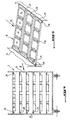
- each tray 10 could comprise four cells, as shown by the Figures 4 and 5 .
- the arrow symbolizes the action of the mechanism for moving the plate towards the conveyor 3.
Landscapes
- Health & Medical Sciences (AREA)
- Surgery (AREA)
- Life Sciences & Earth Sciences (AREA)
- Molecular Biology (AREA)
- General Health & Medical Sciences (AREA)
- Oral & Maxillofacial Surgery (AREA)
- Engineering & Computer Science (AREA)
- Biomedical Technology (AREA)
- Heart & Thoracic Surgery (AREA)
- Medical Informatics (AREA)
- Nuclear Medicine, Radiotherapy & Molecular Imaging (AREA)
- Animal Behavior & Ethology (AREA)
- Pathology (AREA)
- Public Health (AREA)
- Veterinary Medicine (AREA)
- Analysing Materials By The Use Of Radiation (AREA)
- Apparatus For Radiation Diagnosis (AREA)
- Warehouses Or Storage Devices (AREA)
- Surgical Instruments (AREA)
- Fats And Perfumes (AREA)
Description
- L'invention concerne un instrument tel qu'un instrument chirurgical d'un type prédéterminé, défini par sa forme et sa fonction, parmi une pluralité d'instruments de types différents.
- Le document
DE 100 14 542 décrit un instrument chirurgical qui comporte un émetteur d'un signal de radio-fréquence, représentatif du code d'identification de l'instrument, qui permet de vérifier si un instrument a pu être oublié dans la plaie d'intervention chirurgicale, avant la fermeture de celle-ci. - Le document
US 5782764 a pour objet un instrument médical qui est conçu pour être utilisé dans un système d'imagerie à des fins de diagnostic médical, c'est-à-dire pour visualiser la présence de l'instrument sur une image représentant des tissus d'une partie d'un corps d'un patient. - Le document
GB 2409445 - Les instruments chirurgicaux selon l'état de la technique s'avèrent être complexes ou insuffisant pour une identification sure des instruments.
- L'invention a pour but de pallier ces inconvénients.
- L'invention comporte les caractéristiques qui sont énoncées dans la partie caractérisante de la revendication 1.
- D'autres caractéristiques de l'invention sont indiquées dans des revendications dépendantes.
- L'invention sera mieux comprise, et d'autres buts, caractéristiques, détails et avantages de celle-ci apparaîtront plus clairement au cours de la description explicative qui va suivre faite en référence aux dessins schématiques annexés donnés uniquement à titre d'exemple illustrant un mode de réalisation de l'invention et dans lesquels :
- la
figure 1 est une vue schématique, en perspective, d'une installation pour le tri des instruments nécessaires à une opération chirurgicale; - la
figure 2 est une vue de dessus d'un plateau de support d'un instrument; - la
figure 3 est une vue éclatée, d'un plateau de support, selon lafigure 2 ; et - les
figures 4 et 5 illustrent une configuration avantageuse des plateaux set d'un étage de stockage. - Etant donné que l'avantage de l'invention réside dans le fait que les instruments objets de l'invention permettent une reconnaissance de leur type, à l'aide de rayons X, de façon automatique, on les décrit ci-après dans le cadre d'un procédé et d'une installation de tri automatique d'instruments chirurgicaux. Bien entendu, la description est uniquement donnée à titre d'exemple, mais, de façon générale, l'invention est utilisable à toute opération qui implique une sélection et un rangement d'instruments spécifique pour la mise en oeuvre de l'opération.
- En se reportant à la
figure 1 , on constate qu'une installation, pour le tri des instruments nécessaires à une opération chirurgicale, comporte essentiellement, disposé à l'intérieur d'une enceinte à ambiance blanche 1, c'est-à-dire d'une propreté la plus parfaite possible, essentiellement un dispositif de stockage de l'ensemble des instruments chirurgicaux susceptibles d'être utilisés pour les différentes opérations chirurgicales possibles, à l'état propre, un dispositif 3 de transfert des instruments à un convoyeur 4 destiné à les transporter à un poste 5 de reconnaissance de la nature ou du type des instruments et un mécanisme de rangement des instruments après leur reconnaissance dans des récipients 7 dont chacun est destiné à contenir les instruments devant être utilisés pour une opération prédéterminée, un récipient 8 étant prévu pour la réception d'instruments jugés non conformes aux exigences établies pour les opérations chirurgicales. - Le dispositif 2 de stockage de l'ensemble des instruments est réalisé, dans le cas d'exemple, sous forme d'un chariot comportant un certain nombre de niveaux 9 de retenue chacun d'une pluralité de plateaux 10, dans l'exemple représenté 3, dont chacun peut comporter une pluralité d'alvéoles 12 de logement d'un instrument chirurgical 14. Dans le cas d'espèce, pour des raisons de simplification des dessins, chaque plateau ne comporte qu'une alvéole. Les plateaux 10 de chaque niveau 9 du chariot de stockage 2 sont supportés par des éléments de support en forme de rail de glissement 16 fixé chacun à une paroi latérale 17 du chariot orienté en direction du convoyeur 4.
- En se reportant à la
figure 3 , on constate que chaque plateau 10 se compose de deux cadres superposés, en un matériau facilement nettoyable, tel que de l'acier inoxydable, à savoir un élément de cadre inférieur 19 de forme générale rectangulaire et un cadre supérieur 20 de forme complémentaire et susceptible d'être fixé sur le cadre inférieur, par des moyens en forme de clips (non représentés), susceptibles de serrer le cadre supérieur sur le cadre inférieur pour qu'un élément 21 remplaçable, avantageusement à usage unique, en un matériau souple transparent aux rayons X tel que du papier ou du tissu, puisse être inséré à deux de ses bords opposés entre les bords correspondants des deux cadres, pour former une alvéole 12 de logement d'un instrument 14 et ainsi le fond du plateau. Pour la formation aisée des alvéoles et leur maintien, le cadre inférieur 19 est pourvu d'éléments de support 23 en forme d'arcs, au niveau de chaque extrémité longitudinale. Il est avantageux que l'alvéole soit fermée à chaque extrémité longitudinale par une paroi verticale 24 formant l'espace entre le cadre et l'arc correspondant 23. - Comme on le voit sur la
figure 1 , chaque plateau 10 est déplaçable dans le chariot 2, perpendiculairement à son axe longitudinal en prenant appui par les côtés courts 25 sur les rails de glissement 16 du chariot. - L'agencement de transfert des plateaux 10 de chaque étage du chariot comporte, pour pousser les plateaux hors du chariot, un dispositif poussoir 27 et monté verticalement mobile à l'arrière du chariot 2, pour être positionnable à chaque niveau 9 du chariot. Le dispositif comporte un piston poussoir d'un vérin hydraulique qui, lors de son mouvement de sortie, pousse le dernier plateau et déplace ainsi l'ensemble de plateaux en direction du convoyeur.
- Le dispositif de transfert 3 comporte en outre, à l'avant du chariot de stockage 2 de plateaux 10 un cadre 30 de transfert des plateaux 10 du chariot 2 au convoyeur 4, qui est verticalement déplaçable pour pouvoir recevoir les plateaux de chaque niveau 9 de stockage du chariot et pour les transporter ensuite à la hauteur du convoyeur 4 pour que les plateaux puissent être posés sur ce dernier. Plus précisément, dans l'exemple représenté, le cadre de transfert comporte essentiellement deux rails de coulissement 31, chacun étant susceptible d'être aligné, dans une position de réception de plateau d'un niveau ou étage 9, à un rail de glissement 16 de niveau, de façon que les plateaux 10 puissent être déplacés, sous l'effet du dispositif poussoir 27 des rails 16 du chariot aux rails 31 du cadre de transfert 30. Le cadre de transfert est dimensionné de façon à transférer successivement les plateaux 10 au convoyeur 4.
- Le convoyeur 4 est montré, sur la
figure 1 , comme étant réalisé sous forme d'une bande de transport sans fin comportant, essentiellement deux brins plats parallèles 33, destinés au transport des plateaux 10, reliés par des traverses 34. - Pour assurer le transfert des plateaux 10 du cadre de transfert 30 aux brins de convoyeur 33, les rails de support 31 du cadre de transfert s'étendent jusqu'au-dessus du convoyeur et sa portion d'appui de plateau, dans sa position avant de transfert, est abaissable pour permettre la pose des chariots sur les brins du convoyeur situés en dessous. Puis ils s'écartent latéralement et reviennent dans leur position de réception d'un nouveau plateau.
- Le convoyeur 4 transporte les plateaux reçus du chariot de stockage 2, par l'intermédiaire du cadre de transfert 3 au poste de reconnaissance 5 des instruments placés dans les alvéoles 12 des plateaux 10.
- Concernant les instruments chirurgicaux, de fonctions et de formes différentes, ils sont chacun pourvus d'un code d'identité, reconnaissable par le poste 5 de façon que celui-ci soit en mesure de distinguer les instruments apportés par le convoyeur 4 selon leur type spécifique. Plus précisément, le code d'identité de chaque instrument est marqué, sous toute forme appropriée, sur un insert 35 qui est placé dans une cavité appropriée usinée dans l'instrument et fermée ensuite. La
figure 2 montre à titre d'exemple, une pince chirurgicale dans une des branches notée 36 de laquelle est incorporé un insert 35. - Le poste de reconnaissance des instruments est avantageusement un lecteur aux rayons X, en forme d'un portique, à travers lequel passe le convoyeur 4 et qui comporte, disposée au-dessus du convoyeur 4, une source de rayons X 37, tandis qu'un récepteur des rayons ayant traversé l'instrument 14 est disposé sous le convoyeur.
- Pour pouvoir reconnaître le type d'un instrument, d'après son insert, les éléments de celui-ci, qui constituent le code d'identification, doivent être moins transparents aux rayons X que le matériau constitutif de l'instrument. Ce code pourrait résider par exemple dans la forme de l'insert ou des marques prévues sur celui-ci ou encore la forme ou l'emplacement d'une encoche pratiquée dans l'insert. Des inserts de ce genre étant connus en soi, il n'est pas nécessaire de le décrire plus en détail. Les inserts sont avantageusement réalisés en un matériau relativement opaque aux rayons X. Ils pourraient être faits en laiton ou un alliage à base de laiton, alors que les instruments sont en acier inoxydable. De façon générale, pour le choix des matériaux, plus les atomes constitutifs du matériau sont lourds, c'est-à-dire d'une masse atomique élevée, plus ils absorbent les rayons X, donc plus le matériau est opaque à ces rayons X. Pour assurer une reconnaissance fiable des instruments, il est nécessaire que les instruments soient présentés au poste de reconnaissance dans une position toujours clairement définie.
- Après la reconnaissance des instruments, par lecture de leurs inserts, à l'aide des rayons X, l'appareil de rangement 6 saisit les instruments et les range dans les récipients 7 en forme de boîte, sous les ordres d'un dispositif informatique 40.
- Ce dispositif comporte, dans sa mémoire, des protocoles d'opération, un protocole pour chaque type d'opération, qui indique les instruments devant être utilisés au cours de l'opération, le cas échéant dans leur ordre d'utilisation. Etant donné qu'à chaque type d'opération correspond un boîtier 7, les instruments devant être rangés dans cette boîte sont indiqués par le protocole établi pour cette opération. A cette fin, le dispositif informatique 40 identifie tout d'abord, d'après le signal qu'il vient de recevoir du lecteur 38 du poste de reconnaissance, le type de l'instrument qui vient d'être examiné et détermine, en se reportant aux différents protocoles à quel type d'opération et ainsi à quelle boîte 7 un instrument de ce type est destiné. Puis, il donne l'ordre au dispositif de rangement 6 de saisir l'instrument identifié dans le plateau et de le ranger dans la boîte appropriée.
- En comparant les instruments rangés dans une boîte à ceux figurant dans le protocole, le dispositif informatique connaît à tout moment l'état de "remplissage" de chaque boîte 7. S'il constate qu'une boîte est terminée, c'est-à-dire contient tous les instruments nécessaires pour l'opération considérée, la boîte est fermée, par exemple par la mise en place de son couvercle.
- L'installation prévoit également la possibilité d'écarter des instruments jugés non aptes à être utilisés, du circuit d'utilisation, en les plaçant dans une boîte de rebus 8. Diverses raisons pourraient motiver cette mesure, par exemple l'usure d'un instrument, l'impossibilité de l'identifier ou parce qu'il s'agit d'un instrument souillé.
- Concernant le poste de rangement 6, des appareils susceptibles de fonctionner de la manière décrite plus haut, sont largement connus, si bien qu'il n'est pas nécessaire de décrire l'appareil utilisé dans le cadre de l'invention, précisément. Il convient d'indiquer qu'un tel appareil comporte un bras robot capable de saisir les instruments dans leur plateau et de les placer ensuite, en fonction des instructions reçues du dispositif informatique, dans les boîtes appropriées.
- Concernant le fonctionnement de l'installation et le déroulement du procédé ainsi que les différentes étapes de celui-ci, ils découlent de la description qui vient d'être faite. Il va sans le préciser davantage, que pour chaque transfert d'un plateau sur le convoyeur, celui-ci est arrêté pendant un bref instant de temps nécessaire à la pose du plateau. Les arrêts du convoyeur pour le chargement des plateaux et le processus de reconnaissance des instruments par le poste de reconnaissance ainsi que le rangement des instruments sont coordonnés par le dispositif informatique.
- La description de l'invention, qui vient d'être faite, n'a été donnée qu'à titre d'exemple et des multiples modifications peuvent être apportées sans sortir du cadre de l'invention. Pour augmenter la capacité de stockage du chariot 2, chaque plateau 10 pourrait comporter quatre alvéoles, comme le montrent les
figures 4 et 5 . La flèche symbolise l'action du mécanisme de déplacement du plateau vers le convoyeur 3. - Il est à noter que l'installation et le support des instruments ont été décrits pour faciliter la compréhension de l'invention. Ils ne font pas partis de la présente invention et font les objets de demandes de brevets parallèles bénéficiant de la même date de priorité que la présente invention.
Claims (3)
- Instrument tel qu'un instrument chirurgical d'un type prédéterminé, défini par sa forme et sa fonction, parmi une pluralité d'instruments de types différents , et pourvu d'un insert (35) porteur d'un code d'identification de l'instrument (14), disposé dans une cavité fermée préalablement pratiquée dans l'instrument (14) caractérisé en ce que l'insert (35) est réalisé en un matériau relativement opaque aux rayons X et l'instrument est en un matériau relativement transparent à ces rayons X, pour qu'il puisse être reconnu à l'aide des rayons X.
- Instrument selon la revendication 1, caractérisé en ce que les éléments de code de l'insert (35) sont constitués par des éléments tels que la forme spécifique de l'insert, la forme d'une encoche dans l'insert ou des marques de celui-ci.
- Instrument selon la revendication 1 ou 2, l'insert est réalisé en un matériau tel que du laiton ou un alliage à base de laiton, alors que l'instrument est en acier inoxydable.
Applications Claiming Priority (1)
| Application Number | Priority Date | Filing Date | Title |
|---|---|---|---|
| FR0507079A FR2887757B1 (fr) | 2005-07-04 | 2005-07-04 | Instrument tel qu'un instrument chirurgical. |
Publications (2)
| Publication Number | Publication Date |
|---|---|
| EP1741402A1 EP1741402A1 (fr) | 2007-01-10 |
| EP1741402B1 true EP1741402B1 (fr) | 2010-02-24 |
Family
ID=36272265
Family Applications (1)
| Application Number | Title | Priority Date | Filing Date |
|---|---|---|---|
| EP06291092A Not-in-force EP1741402B1 (fr) | 2005-07-04 | 2006-07-03 | Instrument tel qu'un instrument chirurgical |
Country Status (6)
| Country | Link |
|---|---|
| US (1) | US20070010802A1 (fr) |
| EP (1) | EP1741402B1 (fr) |
| AT (1) | ATE458451T1 (fr) |
| CA (1) | CA2551336A1 (fr) |
| DE (1) | DE602006012396D1 (fr) |
| FR (1) | FR2887757B1 (fr) |
Families Citing this family (4)
| Publication number | Priority date | Publication date | Assignee | Title |
|---|---|---|---|---|
| FR2887759B1 (fr) * | 2005-07-04 | 2008-10-17 | Uthemann Cyril De | Procede de tri et de rangement d'instruments tels que des instruments chirurgicaux, et installation pour la mise en oeuvre de ce procede |
| CN105083977B (zh) * | 2014-05-14 | 2018-04-10 | 泰科电子(上海)有限公司 | 自动配料设备 |
| CN108938104B (zh) * | 2018-08-01 | 2020-11-24 | 刘昭阳 | 一种多功能手术器械自动传递装置及传递方法 |
| US10905454B2 (en) | 2018-10-12 | 2021-02-02 | Santosh Kumar BEHERA | Surgical device |
Family Cites Families (5)
| Publication number | Priority date | Publication date | Assignee | Title |
|---|---|---|---|---|
| DE3917876A1 (de) * | 1989-06-01 | 1990-12-06 | Aesculap Ag | System zum beladen eines chirurgischen instrumentensets |
| FR2693303B1 (fr) * | 1992-07-03 | 1994-10-21 | Despres Jean Albert | Dispositif d'identification d'un objet à l'aide d'un insert incorporé à cet objet. |
| US5782764A (en) * | 1995-11-07 | 1998-07-21 | Iti Medical Technologies, Inc. | Fiber composite invasive medical instruments and methods for use in interventional imaging procedures |
| DE10014542C2 (de) * | 2000-03-23 | 2003-11-20 | Aesculap Ag & Co Kg | Erfassungssystem und Erfassungsverfahren für chirurgische Instrumente und Materialien |
| GB2409445B (en) * | 2003-12-22 | 2006-03-29 | Eurocut Ltd | Labelling system |
-
2005
- 2005-07-04 FR FR0507079A patent/FR2887757B1/fr not_active Expired - Fee Related
-
2006
- 2006-06-30 CA CA002551336A patent/CA2551336A1/fr not_active Abandoned
- 2006-06-30 US US11/478,327 patent/US20070010802A1/en not_active Abandoned
- 2006-07-03 EP EP06291092A patent/EP1741402B1/fr not_active Not-in-force
- 2006-07-03 DE DE602006012396T patent/DE602006012396D1/de active Active
- 2006-07-03 AT AT06291092T patent/ATE458451T1/de not_active IP Right Cessation
Also Published As
| Publication number | Publication date |
|---|---|
| US20070010802A1 (en) | 2007-01-11 |
| DE602006012396D1 (de) | 2010-04-08 |
| CA2551336A1 (fr) | 2007-01-04 |
| EP1741402A1 (fr) | 2007-01-10 |
| ATE458451T1 (de) | 2010-03-15 |
| FR2887757A1 (fr) | 2007-01-05 |
| FR2887757B1 (fr) | 2008-05-09 |
Similar Documents
| Publication | Publication Date | Title |
|---|---|---|
| CA2639147C (fr) | Cuvette unitaire pour l'analyse d'un fluide biologique, et dispositif automatique d'analyse in vitro | |
| EP1741401B1 (fr) | Procédé de tri et de rangement d'instruments tels que des instruments chirurgicaux, et installation pour la mise en oeuvre de ce procédé | |
| CA2728587A1 (fr) | Pince adaptee pour saisir un support d'echantillons biologiques, ensemble d'un support echantillons biologiques et d'une pince adaptee, et automate de traitement et/ou d'analyse | |
| EP0675458B1 (fr) | Procédé automatique d'étiquetage et de contrÔle de poches de sang en retour d'analyse et machine en comportant application | |
| EP2066261A1 (fr) | Machine pour remplir de semence des paillettes d'insémination artificielle | |
| EP1741402B1 (fr) | Instrument tel qu'un instrument chirurgical | |
| EP1946255A1 (fr) | Procede et dispositif d'automatisation d'une chaine de distribution de plateaux repas | |
| FR3066275A1 (fr) | Automate pour la conduite automatisee d'analyses, notamment medicales | |
| WO2010072936A1 (fr) | Machine de tri postal avec chariot pour la manipulation des envois postaux | |
| EP1741403B1 (fr) | Récipient, notamment pour instruments chirurgicaux | |
| FR2866251A1 (fr) | Procede pour preparer une tournee du facteur avec a la fois des lettres et des objets de grand format | |
| EP0686565A1 (fr) | Système pour la pesée, l'étiquetage et le triage automatiques de poches contenant des produits sanguins | |
| EP1176106B1 (fr) | Procédé et système pour la préparation automatisée de prises de médicaments à partir d'ordonnances informatisées | |
| EP0573563A1 (fr) | Station de numerisation automatique de diapositives. | |
| EP1693317B1 (fr) | Distributeur automatique de produits | |
| CN217688592U (zh) | 一种高通量数字病理切片自动扫描装置 | |
| EP1726371B1 (fr) | Procédé et machine de tri d'envois postaux avec un séquencement des bacs sur un convoyeur à bande | |
| JP2019095259A (ja) | 処理装置 | |
| EP0271398B1 (fr) | Dispositif et récipient pour la détection et la quantification d'agglutinats | |
| EP0359661A1 (fr) | Portique automatisé de vidage de meubles de stockage | |
| FR2873309A1 (fr) | Procede de traitement d'envois postaux pour la preparation et la separation des tournees de facteur | |
| FR2838114A1 (fr) | Ensemble de stockage, de triage et de preparation d'articles | |
| FR3102982A1 (fr) | Récipient de stockage de déchets contenant des compartiments de stockage. | |
| FR2547417A1 (fr) | Dispositif d'actionnement pour un automatisme comportant une pluralite d'organes mobiles combines | |
| EP0993917A1 (fr) | Préhenseur d'objet et manipulateur équipé d'un tel préhenseur |
Legal Events
| Date | Code | Title | Description |
|---|---|---|---|
| PUAI | Public reference made under article 153(3) epc to a published international application that has entered the european phase |
Free format text: ORIGINAL CODE: 0009012 |
|
| AK | Designated contracting states |
Kind code of ref document: A1 Designated state(s): AT BE BG CH CY CZ DE DK EE ES FI FR GB GR HU IE IS IT LI LT LU LV MC NL PL PT RO SE SI SK TR |
|
| AX | Request for extension of the european patent |
Extension state: AL BA HR MK YU |
|
| 17P | Request for examination filed |
Effective date: 20070709 |
|
| AKX | Designation fees paid |
Designated state(s): AT BE BG CH CY CZ DE DK EE ES FI FR GB GR HU IE IS IT LI LT LU LV MC NL PL PT RO SE SI SK TR |
|
| 17Q | First examination report despatched |
Effective date: 20080214 |
|
| GRAP | Despatch of communication of intention to grant a patent |
Free format text: ORIGINAL CODE: EPIDOSNIGR1 |
|
| GRAS | Grant fee paid |
Free format text: ORIGINAL CODE: EPIDOSNIGR3 |
|
| GRAA | (expected) grant |
Free format text: ORIGINAL CODE: 0009210 |
|
| AK | Designated contracting states |
Kind code of ref document: B1 Designated state(s): AT BE BG CH CY CZ DE DK EE ES FI FR GB GR HU IE IS IT LI LT LU LV MC NL PL PT RO SE SI SK TR |
|
| REG | Reference to a national code |
Ref country code: GB Ref legal event code: FG4D Free format text: NOT ENGLISH |
|
| REG | Reference to a national code |
Ref country code: CH Ref legal event code: EP |
|
| REG | Reference to a national code |
Ref country code: IE Ref legal event code: FG4D Free format text: LANGUAGE OF EP DOCUMENT: FRENCH |
|
| REF | Corresponds to: |
Ref document number: 602006012396 Country of ref document: DE Date of ref document: 20100408 Kind code of ref document: P |
|
| REG | Reference to a national code |
Ref country code: NL Ref legal event code: VDEP Effective date: 20100224 |
|
| LTIE | Lt: invalidation of european patent or patent extension |
Effective date: 20100224 |
|
| PG25 | Lapsed in a contracting state [announced via postgrant information from national office to epo] |
Ref country code: PT Free format text: LAPSE BECAUSE OF FAILURE TO SUBMIT A TRANSLATION OF THE DESCRIPTION OR TO PAY THE FEE WITHIN THE PRESCRIBED TIME-LIMIT Effective date: 20100625 Ref country code: LT Free format text: LAPSE BECAUSE OF FAILURE TO SUBMIT A TRANSLATION OF THE DESCRIPTION OR TO PAY THE FEE WITHIN THE PRESCRIBED TIME-LIMIT Effective date: 20100224 Ref country code: IS Free format text: LAPSE BECAUSE OF FAILURE TO SUBMIT A TRANSLATION OF THE DESCRIPTION OR TO PAY THE FEE WITHIN THE PRESCRIBED TIME-LIMIT Effective date: 20100624 |
|
| PG25 | Lapsed in a contracting state [announced via postgrant information from national office to epo] |
Ref country code: AT Free format text: LAPSE BECAUSE OF FAILURE TO SUBMIT A TRANSLATION OF THE DESCRIPTION OR TO PAY THE FEE WITHIN THE PRESCRIBED TIME-LIMIT Effective date: 20100224 Ref country code: PL Free format text: LAPSE BECAUSE OF FAILURE TO SUBMIT A TRANSLATION OF THE DESCRIPTION OR TO PAY THE FEE WITHIN THE PRESCRIBED TIME-LIMIT Effective date: 20100224 Ref country code: LV Free format text: LAPSE BECAUSE OF FAILURE TO SUBMIT A TRANSLATION OF THE DESCRIPTION OR TO PAY THE FEE WITHIN THE PRESCRIBED TIME-LIMIT Effective date: 20100224 Ref country code: SI Free format text: LAPSE BECAUSE OF FAILURE TO SUBMIT A TRANSLATION OF THE DESCRIPTION OR TO PAY THE FEE WITHIN THE PRESCRIBED TIME-LIMIT Effective date: 20100224 Ref country code: FI Free format text: LAPSE BECAUSE OF FAILURE TO SUBMIT A TRANSLATION OF THE DESCRIPTION OR TO PAY THE FEE WITHIN THE PRESCRIBED TIME-LIMIT Effective date: 20100224 |
|
| REG | Reference to a national code |
Ref country code: IE Ref legal event code: FD4D |
|
| PG25 | Lapsed in a contracting state [announced via postgrant information from national office to epo] |
Ref country code: ES Free format text: LAPSE BECAUSE OF FAILURE TO SUBMIT A TRANSLATION OF THE DESCRIPTION OR TO PAY THE FEE WITHIN THE PRESCRIBED TIME-LIMIT Effective date: 20100604 Ref country code: CY Free format text: LAPSE BECAUSE OF FAILURE TO SUBMIT A TRANSLATION OF THE DESCRIPTION OR TO PAY THE FEE WITHIN THE PRESCRIBED TIME-LIMIT Effective date: 20100224 Ref country code: EE Free format text: LAPSE BECAUSE OF FAILURE TO SUBMIT A TRANSLATION OF THE DESCRIPTION OR TO PAY THE FEE WITHIN THE PRESCRIBED TIME-LIMIT Effective date: 20100224 Ref country code: GR Free format text: LAPSE BECAUSE OF FAILURE TO SUBMIT A TRANSLATION OF THE DESCRIPTION OR TO PAY THE FEE WITHIN THE PRESCRIBED TIME-LIMIT Effective date: 20100525 Ref country code: IE Free format text: LAPSE BECAUSE OF FAILURE TO SUBMIT A TRANSLATION OF THE DESCRIPTION OR TO PAY THE FEE WITHIN THE PRESCRIBED TIME-LIMIT Effective date: 20100224 Ref country code: NL Free format text: LAPSE BECAUSE OF FAILURE TO SUBMIT A TRANSLATION OF THE DESCRIPTION OR TO PAY THE FEE WITHIN THE PRESCRIBED TIME-LIMIT Effective date: 20100224 Ref country code: RO Free format text: LAPSE BECAUSE OF FAILURE TO SUBMIT A TRANSLATION OF THE DESCRIPTION OR TO PAY THE FEE WITHIN THE PRESCRIBED TIME-LIMIT Effective date: 20100224 Ref country code: SE Free format text: LAPSE BECAUSE OF FAILURE TO SUBMIT A TRANSLATION OF THE DESCRIPTION OR TO PAY THE FEE WITHIN THE PRESCRIBED TIME-LIMIT Effective date: 20100224 |
|
| PG25 | Lapsed in a contracting state [announced via postgrant information from national office to epo] |
Ref country code: SK Free format text: LAPSE BECAUSE OF FAILURE TO SUBMIT A TRANSLATION OF THE DESCRIPTION OR TO PAY THE FEE WITHIN THE PRESCRIBED TIME-LIMIT Effective date: 20100224 Ref country code: BG Free format text: LAPSE BECAUSE OF FAILURE TO SUBMIT A TRANSLATION OF THE DESCRIPTION OR TO PAY THE FEE WITHIN THE PRESCRIBED TIME-LIMIT Effective date: 20100524 Ref country code: CZ Free format text: LAPSE BECAUSE OF FAILURE TO SUBMIT A TRANSLATION OF THE DESCRIPTION OR TO PAY THE FEE WITHIN THE PRESCRIBED TIME-LIMIT Effective date: 20100224 |
|
| PLBE | No opposition filed within time limit |
Free format text: ORIGINAL CODE: 0009261 |
|
| STAA | Information on the status of an ep patent application or granted ep patent |
Free format text: STATUS: NO OPPOSITION FILED WITHIN TIME LIMIT |
|
| BERE | Be: lapsed |
Owner name: DE UTHEMANN, CYRIL Effective date: 20100731 |
|
| PG25 | Lapsed in a contracting state [announced via postgrant information from national office to epo] |
Ref country code: DK Free format text: LAPSE BECAUSE OF FAILURE TO SUBMIT A TRANSLATION OF THE DESCRIPTION OR TO PAY THE FEE WITHIN THE PRESCRIBED TIME-LIMIT Effective date: 20100224 |
|
| 26N | No opposition filed |
Effective date: 20101125 |
|
| PG25 | Lapsed in a contracting state [announced via postgrant information from national office to epo] |
Ref country code: MC Free format text: LAPSE BECAUSE OF NON-PAYMENT OF DUE FEES Effective date: 20100731 |
|
| PG25 | Lapsed in a contracting state [announced via postgrant information from national office to epo] |
Ref country code: IT Free format text: LAPSE BECAUSE OF FAILURE TO SUBMIT A TRANSLATION OF THE DESCRIPTION OR TO PAY THE FEE WITHIN THE PRESCRIBED TIME-LIMIT Effective date: 20100224 |
|
| PG25 | Lapsed in a contracting state [announced via postgrant information from national office to epo] |
Ref country code: BE Free format text: LAPSE BECAUSE OF NON-PAYMENT OF DUE FEES Effective date: 20100731 |
|
| PGFP | Annual fee paid to national office [announced via postgrant information from national office to epo] |
Ref country code: CH Payment date: 20111230 Year of fee payment: 6 |
|
| PGFP | Annual fee paid to national office [announced via postgrant information from national office to epo] |
Ref country code: FR Payment date: 20120111 Year of fee payment: 6 |
|
| PGFP | Annual fee paid to national office [announced via postgrant information from national office to epo] |
Ref country code: DE Payment date: 20120102 Year of fee payment: 6 |
|
| PGFP | Annual fee paid to national office [announced via postgrant information from national office to epo] |
Ref country code: GB Payment date: 20120103 Year of fee payment: 6 |
|
| PG25 | Lapsed in a contracting state [announced via postgrant information from national office to epo] |
Ref country code: LU Free format text: LAPSE BECAUSE OF NON-PAYMENT OF DUE FEES Effective date: 20100703 Ref country code: HU Free format text: LAPSE BECAUSE OF FAILURE TO SUBMIT A TRANSLATION OF THE DESCRIPTION OR TO PAY THE FEE WITHIN THE PRESCRIBED TIME-LIMIT Effective date: 20100825 |
|
| PG25 | Lapsed in a contracting state [announced via postgrant information from national office to epo] |
Ref country code: TR Free format text: LAPSE BECAUSE OF FAILURE TO SUBMIT A TRANSLATION OF THE DESCRIPTION OR TO PAY THE FEE WITHIN THE PRESCRIBED TIME-LIMIT Effective date: 20100224 |
|
| REG | Reference to a national code |
Ref country code: CH Ref legal event code: PL |
|
| GBPC | Gb: european patent ceased through non-payment of renewal fee |
Effective date: 20120703 |
|
| REG | Reference to a national code |
Ref country code: FR Ref legal event code: ST Effective date: 20130329 |
|
| PG25 | Lapsed in a contracting state [announced via postgrant information from national office to epo] |
Ref country code: GB Free format text: LAPSE BECAUSE OF NON-PAYMENT OF DUE FEES Effective date: 20120703 Ref country code: DE Free format text: LAPSE BECAUSE OF NON-PAYMENT OF DUE FEES Effective date: 20130201 Ref country code: CH Free format text: LAPSE BECAUSE OF NON-PAYMENT OF DUE FEES Effective date: 20120731 Ref country code: LI Free format text: LAPSE BECAUSE OF NON-PAYMENT OF DUE FEES Effective date: 20120731 Ref country code: FR Free format text: LAPSE BECAUSE OF NON-PAYMENT OF DUE FEES Effective date: 20120731 |
|
| REG | Reference to a national code |
Ref country code: DE Ref legal event code: R119 Ref document number: 602006012396 Country of ref document: DE Effective date: 20130201 |