EP1741412B1 - Knieprothese mit bewegbarem Lager - Google Patents
Knieprothese mit bewegbarem Lager Download PDFInfo
- Publication number
- EP1741412B1 EP1741412B1 EP06022586A EP06022586A EP1741412B1 EP 1741412 B1 EP1741412 B1 EP 1741412B1 EP 06022586 A EP06022586 A EP 06022586A EP 06022586 A EP06022586 A EP 06022586A EP 1741412 B1 EP1741412 B1 EP 1741412B1
- Authority
- EP
- European Patent Office
- Prior art keywords
- insert
- post
- knee prosthesis
- tray
- tibial
- Prior art date
- Legal status (The legal status is an assumption and is not a legal conclusion. Google has not performed a legal analysis and makes no representation as to the accuracy of the status listed.)
- Expired - Lifetime
Links
- 210000003127 knee Anatomy 0.000 title claims abstract description 130
- 230000033001 locomotion Effects 0.000 claims abstract description 61
- 210000002303 tibia Anatomy 0.000 claims description 34
- 230000002093 peripheral effect Effects 0.000 claims description 4
- 238000001356 surgical procedure Methods 0.000 abstract description 3
- 238000006243 chemical reaction Methods 0.000 abstract description 2
- 210000000689 upper leg Anatomy 0.000 description 11
- 238000010276 construction Methods 0.000 description 10
- 210000000629 knee joint Anatomy 0.000 description 10
- 239000007943 implant Substances 0.000 description 6
- 230000006641 stabilisation Effects 0.000 description 6
- 238000011105 stabilization Methods 0.000 description 6
- 238000013150 knee replacement Methods 0.000 description 5
- 239000004698 Polyethylene Substances 0.000 description 3
- 230000008901 benefit Effects 0.000 description 3
- 229920003023 plastic Polymers 0.000 description 3
- 239000004033 plastic Substances 0.000 description 3
- -1 polyethylene Polymers 0.000 description 3
- 229920000573 polyethylene Polymers 0.000 description 3
- 238000000926 separation method Methods 0.000 description 3
- 241001227561 Valgus Species 0.000 description 2
- 241000469816 Varus Species 0.000 description 2
- 239000000853 adhesive Substances 0.000 description 2
- 230000001070 adhesive effect Effects 0.000 description 2
- 239000004568 cement Substances 0.000 description 2
- 230000014759 maintenance of location Effects 0.000 description 2
- 230000013011 mating Effects 0.000 description 2
- 230000005499 meniscus Effects 0.000 description 2
- 239000000126 substance Substances 0.000 description 2
- JJLJMEJHUUYSSY-UHFFFAOYSA-L Copper hydroxide Chemical compound [OH-].[OH-].[Cu+2] JJLJMEJHUUYSSY-UHFFFAOYSA-L 0.000 description 1
- 241001653121 Glenoides Species 0.000 description 1
- 229910001069 Ti alloy Inorganic materials 0.000 description 1
- 210000001264 anterior cruciate ligament Anatomy 0.000 description 1
- 239000002639 bone cement Substances 0.000 description 1
- 230000009194 climbing Effects 0.000 description 1
- 238000004891 communication Methods 0.000 description 1
- 239000002131 composite material Substances 0.000 description 1
- 230000001010 compromised effect Effects 0.000 description 1
- 230000002950 deficient Effects 0.000 description 1
- 230000000694 effects Effects 0.000 description 1
- 230000002708 enhancing effect Effects 0.000 description 1
- 230000005021 gait Effects 0.000 description 1
- 238000002513 implantation Methods 0.000 description 1
- 230000003993 interaction Effects 0.000 description 1
- 239000000463 material Substances 0.000 description 1
- 210000000811 metacarpophalangeal joint Anatomy 0.000 description 1
- 230000003278 mimic effect Effects 0.000 description 1
- 210000002967 posterior cruciate ligament Anatomy 0.000 description 1
- 230000000717 retained effect Effects 0.000 description 1
- 210000004872 soft tissue Anatomy 0.000 description 1
- 230000000087 stabilizing effect Effects 0.000 description 1
Images








Classifications
-
- A—HUMAN NECESSITIES
- A61—MEDICAL OR VETERINARY SCIENCE; HYGIENE
- A61F—FILTERS IMPLANTABLE INTO BLOOD VESSELS; PROSTHESES; DEVICES PROVIDING PATENCY TO, OR PREVENTING COLLAPSING OF, TUBULAR STRUCTURES OF THE BODY, e.g. STENTS; ORTHOPAEDIC, NURSING OR CONTRACEPTIVE DEVICES; FOMENTATION; TREATMENT OR PROTECTION OF EYES OR EARS; BANDAGES, DRESSINGS OR ABSORBENT PADS; FIRST-AID KITS
- A61F2/00—Filters implantable into blood vessels; Prostheses, i.e. artificial substitutes or replacements for parts of the body; Appliances for connecting them with the body; Devices providing patency to, or preventing collapsing of, tubular structures of the body, e.g. stents
- A61F2/02—Prostheses implantable into the body
- A61F2/30—Joints
- A61F2/38—Joints for elbows or knees
- A61F2/3886—Joints for elbows or knees for stabilising knees against anterior or lateral dislocations
-
- A—HUMAN NECESSITIES
- A61—MEDICAL OR VETERINARY SCIENCE; HYGIENE
- A61F—FILTERS IMPLANTABLE INTO BLOOD VESSELS; PROSTHESES; DEVICES PROVIDING PATENCY TO, OR PREVENTING COLLAPSING OF, TUBULAR STRUCTURES OF THE BODY, e.g. STENTS; ORTHOPAEDIC, NURSING OR CONTRACEPTIVE DEVICES; FOMENTATION; TREATMENT OR PROTECTION OF EYES OR EARS; BANDAGES, DRESSINGS OR ABSORBENT PADS; FIRST-AID KITS
- A61F2/00—Filters implantable into blood vessels; Prostheses, i.e. artificial substitutes or replacements for parts of the body; Appliances for connecting them with the body; Devices providing patency to, or preventing collapsing of, tubular structures of the body, e.g. stents
- A61F2/02—Prostheses implantable into the body
- A61F2/30—Joints
- A61F2/38—Joints for elbows or knees
- A61F2/3868—Joints for elbows or knees with sliding tibial bearing
Definitions
- the present invention relates to orthopaedic prosthetic devices, and more particularly to an improved rotating platform, mobile knee prosthesis that incorporates anterior stabilization along with the ability to constrain the movement of the articular surface from rotation and translation, to rotation only.
- Femoral rollback is believed to improve range of motion and extensor mechanism leverage so as to improve efficiency and more accurately replicate natural kinematics.
- Conventional mobile bearing designs may lack the desired effect of femoral rollback, particularly in the absence of the posterior cruciate ligament.
- PS fixed bearing designs provide femoral rollback by articulating a cam on the femoral component with a post on the tibial articular insert during flexion.
- PS fixed bearing designs do not have the advantages of mobile bearing designs with regards to enhanced range of motion, reduced rehabilitation time, improved patellofemoral alignment, increased contact area, and reduced bone-implant interface shear forces.
- any type of posterior stabilized design (fixed bearing or mobile bearing)
- one of the most problematic failure modes of the polyethylene is the fracture of the central post of the insert. This failure can be attributed to "notching" the anterior side of the central post with the anterior most inner-condylar area of the femoral component.
- any mechanism to reduce the probability for impingement of the femoral component against the anterior side of the tibial central post in hyper-extension would reduce the probability for tibial insert post failure due to "notching" and ultimately breaking.
- US 5,879,392 provides a tibial baseplate with a fixed post that extrudes through the stem of the tibial baseplate and through the bearing component and articulates with a recess within the femoral component.
- EP 0916321 A2 provides a femoral component with transverse flanges on the medial and lateral surfaces of the posterior stabilized box that articulates with projections from the medial and lateral surfaces of the post.
- WO 95/35484 provides a bearing component with a post that articulates with a recess within the femoral component.
- the bearing component is limited in rotational, anterior, and posterior movement with respect to the tibial component.
- US 5,370,701 discloses a prosthetic knee which includes a tibial platform, a movable bearing element, a hinge portion, and a femoral component.
- the present invention has as an object a tibial prosthesis and mating articular insert with specially configured stabilization posts.
- the invention enables for the surgeon to convert a mobile bearing articular surface from a fixed to a rotating only or translating only.
- the prosthesis can also provide rotation and translation simultaneously.
- Rotational freedom has more benefit than translational freedom in reducing the potential for fatigue wear.
- a post on the proximal tibial base plate can be positioned with an offset with respect to an oval hole in the articular insert to provide anterior stabilization in the total knee prosthesis.
- the prosthesis of the present invention will be used as part of a total knee surgery when the surgeon chooses to use a prosthesis that incorporates a particular, selected relative motion between tibial tray and tibial insert.
- This present invention consists of a posterior stabilized PS post which is secured to the mobile bearing tibial baseplate allowing only rotational movement.
- the PS post captures a bearing component to the tibial baseplate through an elongated slot in the bearing component.
- the elongated slot in the bearing component allows it to translate anteriorly and posteriorly with respect to the posterior stabilized post.
- the bearing component may also rotate with respect to the tibial baseplate in conjunction with the PS post.
- the bearing component has two concave surfaces that are articulate with the convex surfaces of the femoral component, and that are roughly congruent with the convex surfaces of the femoral component at zero degrees of flexion or full extension.
- the PS post articulates with a recess or cam of the femoral component to provide femoral rollback.
- the PS post should allow for posterior translation, in addition to rotational movement. This posterior movement would allow the post to translate instead of impinging upon the inner-condylar notch area of the femoral component in hyper-extension.
- the PS post has a flat distal surface that articulates with the tibial baseplate.
- a T-slot is located on the distal end and articulates with a T-post on the tibial baseplate.
- a through hole in the PS post is located such that a rotation peg can capture the PS post to the tibial baseplate while the T-slot of the PS is engaged with the T-post of the tibial baseplate.
- the rotation peg allows only rotational freedom of the PS post with respect to the tibial baseplate.
- the PS post has a flange on the medial and lateral surfaces that capture the bearing component through a counterbore on the medial and lateral sides of an elongated slot of the bearing component.
- the elongated slot of the bearing component is larger than the PS post in the anterior-posterior direction such that the bearing component has limited translational with respect to the PS post.
- the bearing component may also rotate with respect to the tibial baseplate in conjunction with the PS post.
- the bearing component has two concave surfaces that are congruent to the convex surfaces of the femoral component.
- a cam mechanism on the femoral component can be a concave cylinder that can be congruent to the convex posterior surface of the PS post. The internal/external rotation of the PS post with the femoral component can maintain this congruency throughout the range of motion unlike designs with a fixed PS post.
- anterior to posterior slot instead of a hole as seen in the inferior view above. This slot would allow for posterior translation of the post relative to the insert/baseplate.
- the PS post may engage the tibial baseplate through a pin means or through a boss of a configuration other than a T-post.
- the PS post may secure the bearing component through the use of slots or other means of capture.
- the PS post may articulate with a closed recess within the femoral component rather than a cam mechanism.
- the means of PS post capture may be with the use of a retaining ring or a cross pin.
- the PS post may not require capture with the fixed bearing articular insert.
- the present invention also provides an improved knee prosthesis apparatus that includes a tibial prosthesis that is configured to be surgically implanted on a patient's transversely cut proximal tibia and a femoral component.
- the femoral component articulate with a tibial insert having a proximal surface that engages the femoral component, the insert having a distal surface that fits against and articulates with the proximal surface of the tibial prosthesis.
- a constraining mechanism joins the tibial insert to the tibial prosthesis in a selective fashion that enables a number of different possible relative motions between the insert and the tibial prosthesis, including anterior to posterior translation with rotation, or rotation only.
- All or part of the constraining mechanism is separable from the tibial prosthesis, and selective removal of all or part of the constraining mechanism determines which of the said possible relative motions will take place.
- the tibial prosthesis can have a fixator for holding the tibial prosthesis on a patient's proximal tibia such as for example, a stem, spike, cement, etc.
- the proximal surface of the insert can have one or more concavities for articulating with the femoral component.
- the femoral component can include an intercondylar surface that is positioned to contact the post, enabling relative motion between the femoral component and the insert to be constrained.
- the femur For knee flexion to be optimized, the femur must roll back on the tibia. This means that the contact point between the femoral and tibial components moves posteriorly.
- roll back is caused by the contact of the bar of the femoral component on the post of the tibial insert. This contact tends to push the insert forward (relative to the tibia).
- the bar and post design In order for normal roll back (with respect to the tibia) to occur, the bar and post design must compensate by causing the femur to roll back on the surface of the tibial insert (the contact point moves posteriorly on the insert). Movement of the contact point causes the stress levels to fluctuate and can lead to fatigue and adhesive wear of the polyethylene.
- the post does not translate, but the insert does. This allows the insert to move posteriorly with the femoral component as the bar/post interaction dictates. However, since the insert moves with the femoral component, the contact point does not move posteriorly on the tibial insert. This provides a more consistent stress level and reduces the tendency for fatigue and adhesive wear.
- the disclosure encompasses a knee prosthesis apparatus comprising: a) a tibial component configured to be surgically implanted on a patient's transversely cut proximal tibia; b) a femoral component; c) a fixator for holding the tibial component on the patient's proximal tibia; d) a tibial insert having a proximal surface that is shaped to engage the femoral component, the insert having a distal surface that fits against and articulates with the proximal surface of the tibial component; e) a constraining mechanism that joins the tibial insert to the tibial component in a selective fashion that enables a number of different possible relative motions between the insert and tibial component including anterior to posterior translation with rotation, or rotation only; and f) wherein all or part of the constraining mechanism is separable from the tibial component and selective removal of all or part of the constraining mechanism determines which of
- the disclosure also encompasses the following.
- a knee prosthesis wherein the tibial prosthesis has a fixator for holding the tibial component on the patient's proximal tibia.
- a knee prosthesis wherein the proximal surface of the insert has one or more concavities for articulating with the femoral component.
- a knee prosthesis wherein there are two concavities that define articulation surfaces on the proximal surface of the tibial insert.
- a knee prosthesis wherein the femoral component includes an intercondylar surface that is positioned to contact the post, enabling relative motion between the femoral component and the insert to be constrained.
- a knee prosthesis wherein the post has a socket and the constraining mechanism includes a locking member that is connectable to the socket on the post.
- a knee prosthesis wherein the constraining mechanism includes a post extending up from the proximal surface of the insert, a slot on the distal surface of the insert, an opening on the proximal surface of the insert that communicates with the slot and a locking plug member that can access and connect to the post from the proximal surface of the insert via the opening.
- a knee prosthesis wherein the femoral component includes an intercondylar surface that is positioned to contact the post, enabling relative motion between the femoral component and the insert to be constrained.
- a knee prosthesis wherein the constraining mechanism includes a socket on the post that receives the locking member, wherein the locking plug member is attached to the post for further defining movement between the insert and tray.
- a knee prosthesis wherein the locking member includes a plug is provided.
- a knee prosthesis wherein the opening is defined by an annular surface that fits closely to the locking plug member when the locking plug member is connected to the pot.
- a knee prosthesis wherein the constraining mechanism includes an opening that extends from the proximal to the distal surface of the insert and a variety of connectable portions which are selectively attachable to or separable from the tray, and wherein the geometry of the various connectable portions relative to the opening enables a user to determine which of the relative motions will take place.
- a knee prosthesis wherein a slot extends through the insert, communicating with both the proximal and distal surfaces of the insert, the slot enabling both anterior to posterior translation and rotation of the insert relative to the tibial component.
- a knee prosthesis wherein the slot has an elongated section that communicates with the distal surface of the insert.
- a knee prosthesis wherein the slot has a generally cylindrically-shaped section that communicates with the proximal surface of the insert.
- a knee prosthesis wherein the slot has a larger transverse cross section at the distal surface of the insert and a smaller transverse cross section at the proximal surface of the insert.
- a knee prosthesis wherein the femoral component includes an intercondylar surface that is positioned to contact the post, enabling relative motion between the femoral component and the insert to be constrained.
- the disclosure encompasses a knee prosthesis apparatus comprising:
- the disclosure also encompasses the following.
- a knee prosthesis wherein the femoral component includes an intercondylar surface that is positioned to contact the post, enabling relative motion between the femoral component and the insert to be constrained.
- a knee prosthesis wherein the post has a socket that receives the locking plug member.
- a knee prosthesis wherein the slot extends through the insert, communicating with both the proximal and distal surfaces of the insert.
- a knee prosthesis wherein the slot has a larger transverse cross section at the distal surface of the insert and a smaller transverse cross section at the proximal surface of the insert.
- a knee prosthesis wherein the channel extends completely through the insert and the locking member extends through the insert from the proximal surface of the insert to connect with the post.
- a knee prosthesis wherein the channel closely conforms to the locking member at the proximal surface of the insert.
- a knee prosthesis apparatus wherein the tibial component has a tibial tray portion configured to be surgically implanted on a patient's transversely cut proximal tibia such that the fixator holds the tray on the patient's proximal tibia and wherein the proximal surface of the tibial insert, includes medial and lateral concavities and a projecting member positioned in between said concavities, the insert having a distal surface that fits against and articulates with the proximal surface of the tray
- a knee prosthesis wherein the proximal surface of the insert has one or more concavities for articulating with the femoral component.
- a knee prosthesis wherein there are two concavities that define the articulation surface.
- a knee prosthesis wherein the post has a socket and the constraining mechanism includes a locking member that is connectable to the socket on the post.
- a knee prosthesis wherein the locking member includes a plug is provided.
- a knee prosthesis wherein the femoral component includes an intercondylar surface that is positioned to contact the post, enabling relative motion between the femoral component and the insert to be constrained.
- a knee prosthesis wherein the constraining mechanism includes a post extending up from the proximal surface of the tibial tray, a slot on the distal surface of the insert, an opening on the proximal surface of the insert that communicates with the slot and a locking plug member that can access and connect to the post from the proximal surface of the insert via the opening.
- a knee prosthesis wherein the constraining mechanism includes a socket on the post that receives the locking plug member, wherein the locking plug member is attached to the post for further defining movement between the insert and tray.
- a knee prosthesis wherein the opening is defined by an annular surface that fits closely to the locking plug member when the locking plug member is connected to the post.
- a knee prosthesis wherein the constraining mechanism includes an opening that extends from the proximal to the distal surface of the insert and a variety of connectable portions which are selectively attachable to or separable from the tray, and wherein the geometry of the various connectable portions relative to the opening enables a user to determine which of the relative motions will take place.
- the tibial component includes a tibial tray portion adapted to be surgically implanted on a patient's transversely cut proximal tibia; and the femoral component engages the tibial component; further comprising a post mounted at the central portion of the proximal surface of the tray, the post having a socket; further wherein the tibial insert having a proximal surface that engages the femoral component, the proximal surface including medial and lateral concavities and a projecting member positioned in between said concavities, the insert having a distal surface that fits against and articulates with the proximal surface of the tray; also comprising a generally vertical channel at the central portion of the insert that extends through the insert, the opening including an elongated slot portion that extends a partial distance through the insert, beginning at the distal surface of the insert and terminating at a position intermediate the proximal and distal surfaces of the insert, the slot
- a knee prosthesis wherein the femoral component includes an intercondylar surface that is positioned to contact the post, enabling relative motion between the femoral component and the insert to be constrained.
- a knee prosthesis wherein the post has a socket that receives the locking plug member.
- a knee prosthesis wherein the slot extends through the insert, communicating with both the proximal and distal surfaces of the insert.
- a knee prosthesis wherein the slot has a larger transverse cross section at the distal surface of the insert and a smaller transverse cross section at the proximal surface of the insert.
- a knee prosthesis wherein the channel extends completely through the insert and the locking member extends through the insert at the proximal surface of the insert to connect with the post.
- a knee prosthesis wherein the channel closely conforms to the locking member at the proximal surface of the insert.
- the disclosure encompasses a knee prosthesis for replacing all or part of a patient's knee joint at the joint between the patient's femur and tibia, comprising: a) a tibial component adapted to be surgically implanted on a patient's transversely cur proximal tibia; b) a fixator for holding the tibial component on the patient's proximal tibia; c) a tibial insert having a distal surface that fits against and articulates with the proximal surface of the tibial component and a proximal femoral articulating surface; d) a femoral component that articulates with the tibial prosthesis at the proximal articulating surface of the tibial insert, the tibial insert having condylar surfaces that engage but not substantially constrain the condylar surfaces of the femoral component; e) a constraining mechanism that enables a selective connection to be made
- Figs. 1 -7 show generally the preferred embodiment of the apparatus of the present invention designated generally by the numeral 10 in Figs. 1 , 6 and 7 .
- Mobile bearing knee prosthesis (10) is placed upon a patient's surgically cut proximal tibia (11) at a surgically cut proximal surface (12) that is preferably flat.
- a tray (13) to be mounted to the proximal tibia (11) at surface (12) as shown in Figs. 6 - 7 .
- Tray (13) has a flat proximal surface (14) and a generally flat distal surface (15) that mates with and faces the surgically prepared surface (12) as shown in Figs. 6 - 7 .
- the tray (13) can provide a plurality of spikes (16) and a stem (17) for enhancing implantation to the patient's proximal tibia (11).
- any other known attachment can be used to affix tray (13) to a patient's proximal tibia such as chemical (e.g. element) or mechanical fasteners (fastener).
- the proximal surface (14) of tray (13) provides a post (18) having an internally threaded socket (19).
- Post (18) is comprised of a generally cylindrically-shaped smaller diameter section (20) and an enlarged flange (21) that mounts to the top of cylindrically-shaped (20) as shown in Figs. 5 and 13-14 .
- Tray (13) has periphery (22).
- a recess (23) is provided in between the proximal surface (14) of tray (13) and flange (21).
- a locking member (24) forms a removable connection with the socket (19).
- Locking member (24) has an externally cylindrical section (25) that provides threads that correspond to the threads of internally threaded socket (19) so that the locking member (24) can be threaded into the socket (19) as shown in Fig. 7 .
- Locking member (24) includes an enlarged cylindrically-shaped head (26) having a tool receptive socket (27) such as a hexagonal socket for example.
- An insert (28) provides a vertical channel (33) that can be placed in communication with post (18) as shown in Figs. 6 - 7 .
- Insert (28) provides a preferably flat distal surface (29) that communicates with the flat proximal surface (14) of tray (13).
- a pair of spaced apart concavities (30, 31) are provided for defining articulation surfaces that cooperate with correspondingly shaped articulating surface on a patient's femur or femoral implant.
- the insert (28) has a periphery (32) that generally corresponds in shape to the periphery (22) of tray (13).
- Insert (28) can be polymeric or metallic or of a composite construction, such as metallic with a polymeric articulating surface(s) or polymeric with a metallic articulating surface(s).
- Vertical channel (33) is comprised of a number of sections that are specially shaped to interact with the post (18) and locking member (24).
- Vertical channel (33) thus includes a proximal, cylindrically-shaped section (34), an oval shaped slot (35), and a distal opening (36).
- the distal opening (36) includes a generally oval section (37) and a somewhat half oval section (38).
- the oval section (38) can track any of three directions including a pure anterior to posterior direction, a direction that is at an angle to a pure anterior to posterior direction; or a direction that is an arcuate or curved path that pivots or rates about a point that is not located along the A/P centreline of the insert.
- Flat surfaces (39, 40) are positioned at the top of and at the bottom of the oval shaped slot (35) as best seen in Figs 8 - 11 .
- the cylindrically-shaped head (26) of locking member (24) closely fits the cylindrically-shaped section (36).
- insert (28) In order to assemble insert (28) to tray (13), the distal surface of (29) of insert (28) is placed next to and generally parallel to the proximal surface (14) of tray (13). Post (18) is aligned with vertical channel (33) of insert (28). During assembly of insert (28) to tray (13), the post (18) is shaped to enter the oval opening portion (37) of distal opening (36). Once the distal surface (29) of insert (28) meets proximal surface (14) of tray (13), flange (21) aligns with oval shaped slot (35) of vertical channel (33). After such assembly, insert (28) is held in position by post (18).
- the apparatus (10) is shown in an assembled position wherein the fastener (24) has been removed so that the insert (28) can move in a translation and rotation and rotation fashion relative to tray (13).
- the fastener (24) has been threadably attached to the internally threaded socket (19) and is in operating position.
- the insert (28) can rotate relative to the tray (13) through an angle (41).
- the apparatus (10) of the present invention provides a mating mechanism between post (18) and the fastener (24) and the insert (28) that defines a constraining mechanism so that the insert (28) may be constrained for rotation only relative to the tray (13).
- FIGs. 18 - 21 and 22 - 25 there is seen various alternate constructions of the post that can be used instead of post 18 when the selected post is fitted to the tibial tray (13).
- Figs. 22 - 25 an alternate construction of the insert (28) is shown with an illustration of the various types of relative motion between the insert and the tibial tray that can be selectively provided to a surgeon.
- a post (42) has a cylindrical outer surface (43) and a circular top (44).
- Post (42) has a rectangular base (45) with a generally flat undersurface and a plurality of four inclined surfaces (46) which provides a means of attaching the post to the tray or the post may be permanently attached to the tray.
- the rectangular base (45) fits tray (13A) socket (47) at its inclied surfaces (48) with a taper lock type connection for example.
- Other types of connections could be used to join post (42) to tray (13A) at socket (47).
- post (49) includes a plurality of four vertical side walls (50) and a plurality of inclined surfaces (51).
- a rectangular flat top (52) is provided opposite a generally flat undersurface of post (49).
- the inclined surfaces (51) of post (49) fit similarly configured inclined surfaces (48) of socket (47) in tray (13A).
- post (53) is generally rectangularly shaped providing a pair of opposed flat larger vertical side walls (54) and a pair of opposed flat smaller end walls (55) with a flat top (56).
- Post (53) has a base (57) that includes four inclined surfaces (58).
- the inclined surfaces (58) form a taper lock connection with four similarly configured inclined surfaces (48) of socket (47) of tray (13A).
- post (59) has a hexagonal shape providing a hexagonally shaped flat top (60).
- Hexagonal post (59) also has a plurality of vertical side walls (61) and a rectangular base (62).
- the base (62) has inclined surfaces (63) that form a taper lock connection with inclined surfaces (48) of tray socket (47) of tray (13A).
- insert (28A) provides a square opening (64) that exactly fits peg (49).
- rotational motion only is indicated by arrow (65) between insert (28A) and tray (13A) when peg (42) is used.
- the rectangular peg (53) enables only translational movement between the insert (28A) and tray (13A) as indicated by arrow (66).
- the hexagonal peg (59) enables both rotational motion as indicated by arrow (65) and translational motion as indicated by arrow (66) between insert (28A) and tray (13A).
- FIG. 37 An alternate embodiment of mobile bearing knee apparatus (110) is shown generally in Fig. 37 .
- the prosthesis (110) is shown positioned upon a patient's proximal tibia (111), specifically upon a flat surgically cut proximal surface (112) as shown.
- tibial tray (113) which can be of metallic construction such as titanium alloy, for example.
- Tray (113) has a flat proximal surface (114) and a flat distal surface (115).
- a plurality of mechanical fasteners such as spikes (116) on surface (115) can be used to enhance fixation of tibial tray (113) to the patient's proximal tibial (111).
- Chemical fasteners e.g. cement
- a stem (117) can also be used to facilitate attachment of prosthesis (110) to the patient's tibia (111) at the tibial intramedually canal.
- the flat proximal surface (114) of tray (113) has a round post (118) with a hollow bore or socket (119).
- the post (118) is spaced inwardly from the periphery (120) of tray (113) as shown in Figs. 26 - 27 .
- the post (118) is preferably positioned with an offset with respect to oval slot (126) in the articular insert to provide anterior stabilization in the total knee prosthesis.
- Insert (121) portion of the present invention, typically a polymeric plastic insert that fits tray (113).
- Insert (121) has a flat distal surface (122) and a proximal surface (123) that includes curved portions. These curved portions are in the form of concavities (124, 125) receive shaped surfaces of a femoral prosthesis after total knee replacement surgery is completed.
- the flat distal surface (122) of insert (121) has an anterior to posterior extending generally oval shaped slot (126) as shown in Fig. 31 .
- the slot (126) receives post (118) during use, enabling the insert (121) to slide in an anterior to posterior direction relative to tray (113).
- the present invention provides a rotating platform, mobile knee prosthesis (110) that incorporates anterior stabilization along with the ability to selectively constrain the movement of he articular surface from rotation and translation to rotation only. This is accomplished by using an opening (136) in insert (121) that communicates with slot (126) as shown in Figs. 29 -31 and 35 - 38 .
- the opening includes a frustoconical portion (137) that corresponds in shape to a similar frustoconically-shaped enlarged annular surface (134) of locking plug member (127).
- the locking plug member (127) is shown more particularly in Figs. 32 - 33 and 37 .
- Locking plug member (127) includes a lower frustoconical surface (128).
- the frustoconical outer surface (128) of locking member (127) below annular reference line (138) is sized and shaped to fit and form a taper lock connection with surface (139) of frustoconical socket (119) of post (118).
- the enlarged annular should has a frustoconical shape as shown in Fig. 32 that corresponds generally to the size and shape of frustoconical portion (137) of opening (136) as shown in Fig. 36 .
- a locking connection is formed between the frustoconical outer surface (128) of locking member (127) and the frustoconical surface (139) of post (118).
- This connection can be a taper lock type connection.
- Locking screw (131) can be used to engage a correspondingly sized and shaped internally threaded opening (132) of tray (113) if desired.
- the locking screw (131) can include a head (140) that is enlarged so that the head (140) is retained by annular should (133) of locking member (137) as shown in Figs. 33 and 37 .
- arrows (141) indicate sliding movement of insert (121) relative to tray (113) as occurs when locking plug member (127) is removed. In such a situation, the insert (121) is free with respect to tray (113). The distal surface (122) of insert (121) slides upon the flat proximal surface (114) of tray (113). Post (118) slides relative to slot (126).
- the second alternate embodiment of the present invention provides a rotating platform, mobile knee prosthesis (110) that incorporates anterior stabilization along with the ability to constrain movement of the articular surface from rotation and translation to rotation only.
- FIGs. 39 and 40 - 51 show a third alternate embodiment of the apparatus of the present invention designated generally by the numeral 142 in Fig. 39 .
- Mobile bearing knee prosthesis (142) includes a tray (143) that can be attached to a patient's surgically cut proximal tibia using a stem (146) for example that occupies the patient's intramedullary canal.
- the tray (143) has a proximal surface (144) that receives an insert (159) and a distal surface (145) that registers upon the proximal tibia after the tibia has been surgically prepared to conform to the underside or distal surface (145) of tray (143).
- the proximal (144) surface of tray (143) provides a frustoconically-shaped socket (147) that can receive either of two selected plugs (148 or 154) (or any of the plug embodiments shown in Figs. 18 - 21 ).
- the first plug (148) is designed to provide rotational movement only between insert (159) and tray (143).
- the plug (148) has a frustoconical surface (149), cylindrical surface (150), bevelled annular surface (151), and a pair of opposed generally parallel flat end surfaces (152, 153).
- the second plug (154) is designed to provide both anterior to posterior translational movement between the insert (159) and tray (153) as well as rotational movement between the insert (159) and tray (153).
- the plug (154) has a frustoconical surface (155), a reduced diameter cylindrical surface (156), and flat end surfaces (157, 158).
- a surgeon selects either of the plugs (148 or 154).
- the frustoconical surfaces (149 or 155) form a tight taper lock fit with a correspondingly shaped frustoconical socket (147) that communicates with the proximal (144) surface of tray (143).
- the insert (159) is placed on the selected plug (148 or 154).
- the shape of the plug (148 or 154) that is selected determines whether or not the insert (159) can achieve only rotational movement relative to tray (143) or both rotational and anterior to posterior translational movement.
- plug (148) In the case of the plug (148), only rotational movement between the insert (159) and the tray (143) can be attained.
- the plug (148) is shorter and thus only communicates with the cylindrically-shaped opening (164) on the bottom or distal surface (162) of insert (159).
- Plug (148) once inserted in socket (147) only enables a rotational movement of the insert (159) on the tray (143).
- the cylindrical surface (150) of plug (148) corresponds in size and shape to the circular opening (164) to accomplish a relatively close fit between cylindrical surface (150) of plug (148) and cylindrical opening (164) on insert (159).
- plug When both rotational and translational anterior to posterior movement are desired, the surgeon selects the plug (154).
- the plug (154) is placed in socket (147) so that frustoconical surface (155) forms a taper lock fit with a correspondingly sized and shaped socket (147) of tray (143).
- the smaller cylindrically-shaped portion (156) of plug (154) is taller in a proximal to distal direction than the cylindrically-shape portion (150) of plug (148).
- the portion (156) fits elongated slot (163) so that the insert (159) can translate in an anterior to posterior direction as the reduced diameter cylindrical portion (156) travels anterior to posterior in the direction of arrow (165) in Fig. 44 .
- the insert can also translate along the path (165) that curved, or along a path (165) that forms an angle with a purely anterior to posterior direction line.
- the line (165) in Fig. 44 shows such a purely anterior to posterior line as the direction of travel.
- Insert (159) also provides proximal concavities (160, 161) for receiving a femoral component of a knee implant.
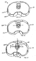
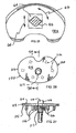
- Figs. 52 - 56 disclose a fourth alternate embodiment of this invention identified as prosthesis (210), comprising a tibial tray (213), a polymeric insert (28), and a locking member (24).
- insert (28) and locking member (24) are the same as described above, but flange (221) is generally D-shaped, having a periphery extending laterally in the medial, lateral, and anterior directions from the out surface of cylindrical section (220), thereby creating recess (223) on the medial, lateral and anterior sides of section (220) (see Figs. 55 - 56 ).
- the assembly of prosthesis (210) is essentially identical to that of prosthesis (10) except for the shape of flange (221).
- Locking member (24) forms a removable connection with the socket (219).
- Locking member (24) has an externally cylindrical section (25) that provides threads that correspond to the threads of internally socket (219) so that the locking member (24) can be threaded into the socket (219) as shown in Fig. 54 .
- insert (28) In order to assemble insert (28) to tray (213), the distal surface (29) of insert (28) is placed next to and generally parallel to the proximal surface (214) of tray (213). Post (218) is aligned with vertical channel (33) of insert (28). During assembly of insert (28) to tray (213), the post (218) is oriented to enter the oval opening portion (37) of distal opening (36). Once the distal surface (29) of insert (28) meets proximal surface (214) of tray (213), flange (221) aligns with oval shaped slot (35) of vertical channel (33). After such assembly, insert (28) is held in position by post (218).
- Figs. 57 - 67 show a fifth alternate embodiment of the apparatus of the present invention designated generally by the numeral 200 in Figs. 57 - 61 .
- the embodiment of Figs. 57 - 61 disclose an alternate construction for a polymeric insert (202) that interconnects with the same tibial tray (13) and stem (17) shown in Figs. 1 , 5 - 7 and 14 - 16 of the preferred embodiment.
- mobile bearing knee prosthesis (200) is shown as including tray (13), polymeric insert (202), and femoral component (236).
- the femoral component (236) is shown attached to a patient's surgically cut distal demur (201).
- Polymeric insert (202) (see Figs. 62-67 ) has a flat distal surface (203) and a proximal surface with a pair of concavities (204, 205). Insert (202) also has periphery (206) and vertical channel (207). The vertical channel (207) can be a slotted arrangement such as that shown in the preferred embodiment of Figs. 1 - 17 and designated generally by the numeral 33.
- the connection between post (18) of tray (13) and insert (202) can be the same connection that is shown and described with respect to the preferred embodiment of Figs. 1 -17 and shown particularly in Figs. 1 - 7 and 15 - 17 , or as shown in Figs. 52 -56 .
- Vertical channel (207) can include a proximal cylindrically-shaped section (208), an oval shaped slot (209), and a distal opening (224).
- the distal opening (224) can include an oval section (226) and a half oval section (227) as shown in Fig. 66 .
- Flat surface (225) extends posteriorly of vertical channel (207) more particularly posteriorly of the proximal cylindrically-shaped section (208), as shown in Figs. 64 - 65 .
- Flat surfaces (228, 229) register with the flange (21) of post (18), respectively above and below the flange (21) to thereby prevent separation of polymeric insert (202) from post (18) unless the post (18) is aligned with oval section (226) of distal opening (224).
- insert (202) can be separated from tray (13).
- insert (202) provides a central post (230).
- Post (230) has proximal surface (231), anterior surface (232), posterior surface (233), and sides (234, 235).
- Femoral component (236) is shown in Figs. 57 -61 .
- Femoral component (236) has anterior portion (237), a pair of posterior condylar portions (238, 239) and distal condylar portions (240, 241).
- Femoral component (236) has central opening (242) and a horizontal bar cam (243) that extends between posterior condylar portions (238, 239) as best seen in Figs. 59 and 68 .
- a pair of vertical walls (244, 245) extend along opposing sides of central opening (242) and connect to both of the posterior condylar portions (238, 239) and to horizontal bar (243).
- the vertical walls (230, 231) also extend to and connect to surfaces (248, 249, 250).
- the vertical walls (244, 245) can be generally parallel.
- Femoral component (236) provides a plurality of flat surfaces that register against and conform to surgically cut flat surfaces that are provided on the patient's distal femur (201) as shown in Fig. 58 .
- These flat surfaces include flat surface (246) is an anterior surface, surface (247) which is a diagonally extending anterior surface that spans between anterior surface (246) and distal surface (248).
- Distal surface (248) spans between diagonal surface (247) and posterior diagonal surface (249).
- Posterior surface (250) is generally parallel to anterior flat surface (246).
- These five flat surfaces (246 - 250) of femoral component (236) register against and conform to five surgically cut surfaces on a patient's distal femur (201).
- Femoral component (236) can be securely fashioned to the patient's femur (201) using bone cement for example.
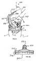
- Figs. 60 - 61 a range of motion for the patient's knee fitted with mobile bearing knee prosthesis (200) as illustrated with arrows (252, 253).
- the patient's central longitudinal axis (251) of the distal femur (201) is shown rotating posteriorly in the direction of arrow (253).
- the anterior surface (237) of femoral component (236) is shown rotating in the direction of arrow (252).
- Fig. 60 shows an extended position of the patient's knee wherein the longitudinal axis (251) of the femur (201) is generally aligned with the central longitudinal axis of the patient's tibia (11).
- the knee is shown in a flexed position.
- central post (230) In this position, horizontal bar cam (243) of femoral component (222) registers against the posterior surface (233) of central post (230) of polymeric insert (202). In this position, the central post (230) causes femoral roll back on the tibia articular insert (202).
- the posterior aspect of the tibia articular surface at (233) provides a lift that is created by generally following the curvature of the femoral component (236) in extension. This will provide a high degree of surface contact, conformity, subsequently providing low contact stress, in extension, where most of gait occurs.
- the post (230) can have a square or rectangular base that fits snugly within the central opening (242) of the femoral component (236).
- the horizontal bar cam (243) acts as a cam on the femoral component (236) to engage the post (230) at surface (233) on the tibial component (202), causing the femoral posterior condyles (238, 239) to roll back onto the tibial articular concavity surfaces (204, 205).
- This "roll back” coupled with “climbing” the posterior aspect of the tibial articular surface at (233), causes the femoral component (236) to be located out of the lowest aspect of the tibial articular surfaces (204, 205).
- any type of varus/valgus loading of the joint will cause one of the femoral condyles to apply higher downward loads than the opposing condyle.
- the tibial component (202) With a differential in loads, the tibial component (202) will freely spin until the higher loaded condyle displaces to the low point of the tibial articular surface.
- the central tibial post (216) forces the opposite condyle out of the posterior aspect of the tibial articular surface, thus creating a spin out.
- the present invention allows for a free, unlimited rotation of the tibial insert (202) relative to its baseplate (13). All of the rotational constraints occurs between the femoral component (236) and the insert (202).
- the present invention builds conformity of the central post (230) of the insert (202) relative to the box of the femur in rotation, but allowing for varus/valgus tilting.
- the present invention produces a generally trapezoidal insert post (230).
- a mobile bearing knee prosthesis features a two-part polymeric insert that includes first member (255) shown in Figs. 69 -75 and a second member (264) shown in Figs. 69 and 76 - 81 .
- Polymeric insert (255) (see Figs. 70 - 75 ) has a central opening (256) that is bordered by a pair of spaced apart, generally parallel shoulders (257, 258) upon which second member (264) slides fore and aft.
- the insert (255) has a periphery (259) a proximal surface with a pair of concavities (260, 261).
- the insert member (255) includes a flat distal surface (262).
- the second insert member (264) has a proximal surface (265), a distal surface (267) and a passageway (263) that extends between the surfaces (265, 267).
- a pair of spaced apart, generally parallel shoulders (268, 269) are provided on opposing sides of insert (9264) as shown in Figs. 77 , 79 and 81 .
- Flat surfaces (270, 271) are also provided on opposing sides of insert member (264).
- the surface (270) is generally perpendicular to shoulder (268).
- the surface (277) is generally perpendicular to the shoulder (267) as shown in Fig. 79 .
- Insert member (264) provides a post (272).
- Post (272) has flat, proximal surface (273), anterior surface (274), posterior surface (275), and sides (276, 277).
- the member (264) provides a curved anterior surface (278) that is correspondingly shaped to and fits against the correspondingly shaped concave surface (279) of member (255) at opening (256).
- insert member (264) During use, the shoulders (268, 269) of insert member (264) fit against and slide upon the shoulders (257, 258) of insert member (255). Flat surfaces (270, 271) of insert member (264) engage and slide against flat surfaces (280, 281) of insert (255).
- the insert member (264) slides upon the insert member (255) in an anterior to posterior direction because the opening (256) is longer than the insert member (264).
- the opening (256) is larger in an anterior to posterior direction than the length of the insert member (264) measured from an anterior to posterior direction such as between surfaces (278) and (280).
- the present invention includes a posterior stabilizing post (272) secured to the central insert member (264).
- the posterior stabilized post (272) captures or is captured by bearing insert component (255) to the tibial baseplate (13) through an elongated slot or opening (256) in the bearing component (255).
- the elongated opening or slot (256) in the bearing component member (255) allows it to translate anteriorly and posteriorly with respect to the posterior stabilized post (272) of the insert member (264).
- the bearing component (255) may also rotate with respect to the tibial baseplate (13) in conjunction with the posterior stabilized post (272).
- the bearing component (255) has two concave surfaces (260, 261) that are configured to articulate with the convex surfaces [condylar portions](240, 241) of the femoral component (236) at full extension.
- the posterior stabilized post (272) articulates with a horizontal bar cam (243) of the femoral component (236) to provide femoral roll back.
- the bearing design of the present invention thus consists of a bearing articular insert (255) with a separate posterior stabilized post component (264) that may have one or more degrees of freedom.
- the bearing articular insert (251) has two concave surfaces (260, 261) that articulate with the convex surfaces [condylar portions](240, 241) of the femoral component (236) at full extension.
- the posterior stabilized post (272) articulates with a recess or cam (243) of the femoral component (236) to provide femoral roll back.
- the rotational freedom of the posterior stabilized post (272) maintains contact with the femoral bar cam (243) during external or internal rotation of femoral component (236).
- the posterior stabilized member (255) has a flat distal surface (262) that articulates with the tibial baseplate (13).
- a tee slot (266) is located n the distal surface (267) and articulates with a tee post (18) on the tibial baseplate (13) (see Figs. 1 - 17 for such a tee slot and tee post connection).
- a through hole (263) in the component (264) is located such that a rotation peg (such as peg (24) in Figs.
- the elongated slot (256) of the bearing component (255) is larger than the posterior stabilized post carrying component (255) in the anterior-posterior direction such that the bearing component has limited translation with respect to the posterior stabilized post.
- the bearing component (255) may also rotate with respect to the tibial baseplate (13) in conjunction with posterior stabilized post component (264).
- Horizontal bar cam mechanism (243) on the femoral component (236) is preferably a concavely shaped cylinder as shown in Figs. 59 and 68 , that registers against and engages the convex posterior surface (275) of the posterior stabilized post (272).
- the internal/external rotation of the posterior stabilized post component (264) with the femoral component (236) maintains this contact throughout the range of motion.
- the second (central) insert member (264) could rotate only with respect to the tibial prosthesis, and the first (peripheral) insert member could both rotate and translate with respect to the tray.
Landscapes
- Health & Medical Sciences (AREA)
- Orthopedic Medicine & Surgery (AREA)
- Physical Education & Sports Medicine (AREA)
- Cardiology (AREA)
- Oral & Maxillofacial Surgery (AREA)
- Transplantation (AREA)
- Engineering & Computer Science (AREA)
- Biomedical Technology (AREA)
- Heart & Thoracic Surgery (AREA)
- Vascular Medicine (AREA)
- Life Sciences & Earth Sciences (AREA)
- Animal Behavior & Ethology (AREA)
- General Health & Medical Sciences (AREA)
- Public Health (AREA)
- Veterinary Medicine (AREA)
- Prostheses (AREA)
- Materials For Medical Uses (AREA)
Claims (27)
- Eine Knieprothesen(210)-Vorrichtung, die Folgendes beinhaltet:a. eine Tibiakomponente, die einen Tibiaplatten(213)-Teil umfasst, der konfiguriert ist, um auf einer transversal geschnittenen proximalen Tibia eines Patienten chirurgisch implantiert zu werden;b. ein Fixiermittel zum Halten der Tibiakomponente auf der proximalen Tibia des Patienten;c. eine Femurkomponente (236); undd. einen Tibiaeinsatz, dadurch gekennzeichnet, dass der Tibiaeinsatz ein erstes und zweites entfernbar verknüpfbares Element aufweist, umfassend ein peripheres Element, das eine zentrale Öffnung aufweist, und ein zentrales Element, das sich mit der zentralen Öffnung verknüpft, wobei der Einsatz eine distale Oberfläche aufweist, die gegen die proximale Oberfläche der Tibiakomponente passt und mit dieser ein Gelenk bildet; und dadurch, dass die Knieprothesenvorrichtung ferner Folgendes beinhaltet:e. einen Einschränkungsmechanismus, der während der Verwendung den Einsatz auf eine selektive Weise mit dem Tibiaplatten(213)-Teil verbindet, die eine Anzahl an unterschiedlichen möglichen relativen Bewegungen zwischen dem Einsatz und der Tibiaplatte ermöglicht, einschließlich Translation von vorne nach hinten und Rotation oder nur Rotation; undf. wobei der gesamte Einschränkungsmechanismus oder ein Anteil davon von der Platte (213) trennbar ist und die selektive Entfernung des gesamten Einschränkungsmechanismus oder eines Anteils davon festlegt, welche der möglichen relativen Bewegungen ablaufen werden.
- Knieprothese gemäß Anspruch 1, wobei der Einschränkungsmechanismus einen Pfosten (218) umfasst, der sich von der proximalen Oberfläche des Tibiaeinsatzes nach oben erstreckt.
- Knieprothese gemäß Anspruch 2, wobei die Femurkomponente (236) eine interkondyläre Oberfläche umfasst, die positioniert ist, um mit dem Pfosten (218) in Kontakt zu kommen, was ein Einschränken der relativen Bewegung zwischen der Femurkomponente und dem Einsatz ermöglicht.
- Knieprothese (210) gemäß Anspruch 1, wobei sich das zentrale Element verschiebbar mit dem peripheren Element verknüpft.
- Knieprothese (210) gemäß Anspruch 1, wobei sich das zentrale Element mit der Platte (213) verknüpft und sich das periphere Element mit dem zentralen Element verknüpft.
- Knieprothese (210) gemäß Anspruch 1, wobei die proximale Oberfläche des Einsatzes eine oder mehrere Höhlungen (261, 266) zum Gelenkbilden mit der Femurkomponente aufweist.
- Knieprothese (210) gemäß Anspruch 1, wobei zwei Höhlungen (260, 261) vorhanden sind, welche die Gelenkbildungsoberfläche definieren.
- Knieprothese (210) gemäß Anspruch 1, wobei der Einschränkungsmechanismus einen Pfosten (218) umfasst, der sich von der proximalen Oberfläche der Tibiaplatte nach oben erstreckt.
- Knieprothese (210) gemäß Anspruch 8, wobei sich das zentrale Element mit dem Pfosten (218) verknüpft.
- Knieprothese (210) gemäß Anspruch 1, wobei der Pfosten (218) eine Fassung (129) aufweist und der Einschränkungsmechanismus ein Sicherungsstopfenelement (127) umfasst, das mit der Fassung auf dem Pfosten (218) verknüpfbar ist.
- Knieprothese (210) gemäß Anspruch 1, wobei der Einschränkungsmechanismus einen Pfosten, der sich von der proximalen Oberfläche der Tibiaplatte nach oben erstreckt, eine Aussparung (126) auf der distalen Oberfläche des Einsatzes, eine Öffnung auf der proximalen Oberfläche des Einsatzes, mit der Aussparung in Verbindung stehend, und ein Sicherungsstopfenelement (127), das von der proximalen Oberfläche des Einsatzes über die Öffnung Zugang zu dem Pfosten haben und mit dieser verknüpft werden kann, umfasst.
- Knieprothese (210) gemäß Anspruch 11, wobei die Femurkomponente eine interkondyläre Oberfläche umfasst, die positioniert ist, um mit dem Pfosten (218) in Kontakt zu kommen, was ein Einschränken der relativen Bewegung zwischen der Femurkomponente und dem Einsatz ermöglicht.
- Knieprothese (210) gemäß Anspruch 1, wobei der Einschränkungsmechanismus eine Fassung auf dem Pfosten (218) umfasst, die das Sicherungsstopfenelement (127) aufnimmt, wobei das Sicherungsstopfenelement (127) an dem Pfosten (218) befestigt wird, um die Bewegung zwischen dem Einsatz und der Platte (213) ferner zu definieren.
- Knieprothese (210) gemäß Anspruch 1, wobei die Öffnung durch eine ringförmige Oberfläche definiert ist, die eng an das Sicherungsstopfenelement (127) passt, wenn das Sicherungsstopfenelement (127) mit dem Pfosten (218) verknüpft ist.
- Knieprothese (210) gemäß Anspruch 1, wobei der Einschränkungsmechanismus eine Öffnung, die sich von der proximalen zu der distalen Oberfläche des Einsatzes erstreckt, und eine Vielfalt von verknüpfbaren Teilen, die selektiv an der Platte (213) befestigt oder von dieser getrennt werden können, umfasst, und wobei die Geometrie der verschiedenen verknüpfbaren Teile relativ zu der Öffnung einem Benutzer ermöglicht, festzulegen, welche der relativen Bewegungen ablaufen wird.
- Knieprothesen(210)-Vorrichtung gemäß Anspruch 1, die ferner Folgendes beinhaltet:a. einen an dem zentralen Teil der proximalen Oberfläche der Platte montierte Pfosten (218), wobei der Pfosten eine Fassung aufweist;b. einen im Allgemeinen vertikalen Kanal (33) an dem zentralen Teil des Einsatzes, der sich durch den Einsatz erstreckt, wobei die Öffnung eine längliche Aussparung umfasst, die sich eine Teilstrecke durch den Einsatz erstreckt, beginnend an der distalen Oberfläche des Einsatzes und endend an einer Position zwischen der proximalen und der distalen Oberfläche des Einsatzes, wobei sich die Aussparung (126) im Allgemeinen entlang einer Linie von vorne nach hinten erstreckt;c. die Aussparung, die sich entfernbar mit dem Pfosten (218) der Platte (213) verknüpft und sich mit Bezug auf diesen verschiebt; undd. ein Sicherungselement zum selektiven Sichern des Einsatzes und der Platte miteinander mit einer Rotierverknüpfung, wobei sich das Sicherungselement durch den Einsatz erstreckt, um sich mit dem Pfosten auf der Platte zu verknüpfen; wobeie. der Einsatz und die Platte (213) konfiguriert sind, um eine ausgewählte relative Bewegung zwischen dem Einsatz und der Platte durch entsprechendes Verknüpfen oder Lösen des Sicherungselements zu ermöglichen, wobei der Einsatz relativ zu der Platte (213) rotierbar ist, wenn das Sicherungselement mit dem Pfosten (218) verknüpft ist; undf. wobei der Einsatz ein erstes und zweites verknüpfbares Element umfasst, die relativ zu der Platte (213) rotierbar sind, wenn das Sicherungselement mit dem Pfosten (218) zusammengesetzt ist.
- Knieprothese (210) gemäß Anspruch 16, wobei der Einschränkungsmechanismus einen Pfosten (218) umfasst, der sich von der proximalen Oberfläche des Tibiaeinsatzes nach oben erstreckt.
- Knieprothese (210) gemäß Anspruch 17, wobei die Femurkomponente (236) eine interkondyläre Oberfläche umfasst, die positioniert ist, um mit dem Pfosten (218) in Kontakt zu kommen, was ein Einschränken der relativen Bewegung zwischen der Femurkomponente und dem Einsatz ermöglicht.
- Knieprothese (210) gemäß Anspruch 16, wobei der Tibiaeinsatz einen Pfosten (218) aufweist.
- Knieprothese (210) gemäß Anspruch 16, wobei der Pfosten eine Fassung aufweist, die das Sicherungsstopfenelement (127) aufnimmt.
- Knieprothese (210) gemäß Anspruch 16, wobei sich die Aussparung (126) durch den Einsatz erstreckt und sowohl mit der proximalen als auch der distalen Oberfläche des Einsatzes in Verbindung steht.
- Knieprothese (210) gemäß Anspruch 20, wobei die Aussparung (126) an der distalen Oberfläche des Einsatzes einen größeren transversalen Querschnitt und an der proximalen Oberfläche des Einsatzes einen kleineren transversalen Querschnitt aufweist.
- Knieprothese (210) gemäß Anspruch 20, wobei sich der Kanal (33) vollständig durch den Einsatz erstreckt und sich das Sicherungselement an der proximalen Oberfläche des Einsatzes durch den Einsatz erstreckt, um sich mit dem Pfosten (218) zu verknüpfen.
- Knieprothese (210) gemäß Anspruch 18, wobei sich der Kanal (33) an der proximalen Oberfläche des Einsatzes eng an den Sicherungsstopfen anpasst.
- Knieprothese (210) gemäß Anspruch 18, wobei das erste und das zweite verknüpfbare Element während der Verwendung verschiebbar verknüpft sind.
- Knieprothese (210) gemäß Anspruch 1, bei der die Femurkomponente (236) mit dem Einsatz ein Gelenk bildet.
- Knieprothese (210) gemäß Anspruch 16, bei der die Femurkomponente in die Tibiakomponente eingreift.
Applications Claiming Priority (2)
| Application Number | Priority Date | Filing Date | Title |
|---|---|---|---|
| US09/670,186 US6428577B1 (en) | 1998-05-20 | 2000-09-26 | Mobile bearing knee prosthesis |
| EP01975375A EP1322262B1 (de) | 2000-09-26 | 2001-09-26 | Knieprothese mit bewegbarem lager |
Related Parent Applications (2)
| Application Number | Title | Priority Date | Filing Date |
|---|---|---|---|
| EP01975375.5 Division | 2001-09-26 | ||
| EP01975375A Division EP1322262B1 (de) | 2000-09-26 | 2001-09-26 | Knieprothese mit bewegbarem lager |
Publications (3)
| Publication Number | Publication Date |
|---|---|
| EP1741412A2 EP1741412A2 (de) | 2007-01-10 |
| EP1741412A3 EP1741412A3 (de) | 2007-08-22 |
| EP1741412B1 true EP1741412B1 (de) | 2011-12-21 |
Family
ID=24689349
Family Applications (2)
| Application Number | Title | Priority Date | Filing Date |
|---|---|---|---|
| EP06022586A Expired - Lifetime EP1741412B1 (de) | 2000-09-26 | 2001-09-26 | Knieprothese mit bewegbarem Lager |
| EP01975375A Expired - Lifetime EP1322262B1 (de) | 2000-09-26 | 2001-09-26 | Knieprothese mit bewegbarem lager |
Family Applications After (1)
| Application Number | Title | Priority Date | Filing Date |
|---|---|---|---|
| EP01975375A Expired - Lifetime EP1322262B1 (de) | 2000-09-26 | 2001-09-26 | Knieprothese mit bewegbarem lager |
Country Status (10)
| Country | Link |
|---|---|
| US (1) | US6428577B1 (de) |
| EP (2) | EP1741412B1 (de) |
| JP (2) | JP4746257B2 (de) |
| AT (2) | ATE537782T1 (de) |
| AU (1) | AU2001294709A1 (de) |
| CA (1) | CA2423439C (de) |
| DE (1) | DE60127275T2 (de) |
| ES (1) | ES2282296T3 (de) |
| PT (1) | PT1322262E (de) |
| WO (1) | WO2002026169A2 (de) |
Cited By (5)
| Publication number | Priority date | Publication date | Assignee | Title |
|---|---|---|---|---|
| US8142510B2 (en) | 2007-03-30 | 2012-03-27 | Depuy Products, Inc. | Mobile bearing assembly having a non-planar interface |
| US8147557B2 (en) | 2007-03-30 | 2012-04-03 | Depuy Products, Inc. | Mobile bearing insert having offset dwell point |
| US8147558B2 (en) | 2007-03-30 | 2012-04-03 | Depuy Products, Inc. | Mobile bearing assembly having multiple articulation interfaces |
| US8328874B2 (en) | 2007-03-30 | 2012-12-11 | Depuy Products, Inc. | Mobile bearing assembly |
| US8764841B2 (en) | 2007-03-30 | 2014-07-01 | DePuy Synthes Products, LLC | Mobile bearing assembly having a closed track |
Families Citing this family (117)
| Publication number | Priority date | Publication date | Assignee | Title |
|---|---|---|---|---|
| US20050209703A1 (en) * | 1999-04-02 | 2005-09-22 | Fell Barry M | Surgically implantable prosthetic system |
| US7338524B2 (en) * | 1999-05-10 | 2008-03-04 | Fell Barry M | Surgically implantable knee prosthesis |
| US7491235B2 (en) * | 1999-05-10 | 2009-02-17 | Fell Barry M | Surgically implantable knee prosthesis |
| US7297161B2 (en) * | 1999-05-10 | 2007-11-20 | Fell Barry M | Surgically implantable knee prosthesis |
| US20050033424A1 (en) * | 1999-05-10 | 2005-02-10 | Fell Barry M. | Surgically implantable knee prosthesis |
| US6558426B1 (en) | 2000-11-28 | 2003-05-06 | Medidea, Llc | Multiple-cam, posterior-stabilized knee prosthesis |
| US6485519B2 (en) | 2001-01-29 | 2002-11-26 | Bristol-Myers Squibb Company | Constrained prosthetic knee with rotating bearing |
| US6719800B2 (en) * | 2001-01-29 | 2004-04-13 | Zimmer Technology, Inc. | Constrained prosthetic knee with rotating bearing |
| DE10200263B4 (de) * | 2002-01-07 | 2007-01-25 | Plus Orthopedics Ag | Tibiakomponente einer Kniegelenkendoprothese |
| US20040034432A1 (en) * | 2002-02-11 | 2004-02-19 | Dean Hughes | Mobile bearing tibial base prosthetic devices employing oxidized zirconium surfaces |
| CA2475078C (en) | 2002-02-20 | 2010-05-04 | Thomas M. Coon | Knee arthroplasty prosthesis and method |
| US6923832B1 (en) * | 2002-03-21 | 2005-08-02 | Trigon Incorporated | Revision tibial component |
| AU2003287190A1 (en) | 2002-10-23 | 2004-05-13 | Alastair J. T. Clemow | Modular femoral component for a total knee joint replacement for minimally invasive implantation |
| DE60336013D1 (de) | 2002-12-20 | 2011-03-24 | Smith & Nephew Inc | Hochleistungsknieprothese |
| US7452381B2 (en) * | 2003-01-30 | 2008-11-18 | Mayo Foundation For Medical Education And Research | Radial head replacement system |
| EP1601316A1 (de) * | 2003-02-04 | 2005-12-07 | Zimmer Austin, Inc. | Drehbares/nicht drehbares tibiaplatten-/einsatzsystem |
| EP1684672B1 (de) | 2003-10-17 | 2020-03-25 | Smith & Nephew, Inc. | Gelenkeinsatz mit hoher biegung |
| US20050197713A1 (en) * | 2004-03-01 | 2005-09-08 | Catlin Mark G. | Ternary single-phase ceramic medical devices |
| EP1574185B1 (de) * | 2004-03-09 | 2012-05-23 | Zimmer Technology, Inc. | Tibiale Kniekomponente mit einem mobilen Lagerteil |
| US20050203632A1 (en) * | 2004-03-09 | 2005-09-15 | Daniels Michael E. | Tibial implant with a through post |
| JP3915989B2 (ja) * | 2004-03-17 | 2007-05-16 | 徹 勝呂 | 人工膝関節 |
| US8303604B2 (en) | 2004-11-05 | 2012-11-06 | Biomet Sports Medicine, Llc | Soft tissue repair device and method |
| US7749250B2 (en) | 2006-02-03 | 2010-07-06 | Biomet Sports Medicine, Llc | Soft tissue repair assembly and associated method |
| US9017381B2 (en) | 2007-04-10 | 2015-04-28 | Biomet Sports Medicine, Llc | Adjustable knotless loops |
| US8137382B2 (en) | 2004-11-05 | 2012-03-20 | Biomet Sports Medicine, Llc | Method and apparatus for coupling anatomical features |
| US8298262B2 (en) | 2006-02-03 | 2012-10-30 | Biomet Sports Medicine, Llc | Method for tissue fixation |
| US8118836B2 (en) | 2004-11-05 | 2012-02-21 | Biomet Sports Medicine, Llc | Method and apparatus for coupling soft tissue to a bone |
| US9801708B2 (en) | 2004-11-05 | 2017-10-31 | Biomet Sports Medicine, Llc | Method and apparatus for coupling soft tissue to a bone |
| US8088130B2 (en) | 2006-02-03 | 2012-01-03 | Biomet Sports Medicine, Llc | Method and apparatus for coupling soft tissue to a bone |
| US7905904B2 (en) | 2006-02-03 | 2011-03-15 | Biomet Sports Medicine, Llc | Soft tissue repair device and associated methods |
| US8128658B2 (en) | 2004-11-05 | 2012-03-06 | Biomet Sports Medicine, Llc | Method and apparatus for coupling soft tissue to bone |
| US7909851B2 (en) | 2006-02-03 | 2011-03-22 | Biomet Sports Medicine, Llc | Soft tissue repair device and associated methods |
| US8361113B2 (en) | 2006-02-03 | 2013-01-29 | Biomet Sports Medicine, Llc | Method and apparatus for coupling soft tissue to a bone |
| US7658751B2 (en) | 2006-09-29 | 2010-02-09 | Biomet Sports Medicine, Llc | Method for implanting soft tissue |
| US8002777B2 (en) * | 2005-06-09 | 2011-08-23 | Biomet Manufacturing Corp. | Instrumentation and method for implanting a curved stem tibial tray |
| US7507215B2 (en) | 2005-07-08 | 2009-03-24 | Jri Development Group, Llc | Orthotic brace |
| US20070100460A1 (en) * | 2005-10-27 | 2007-05-03 | Rhodes James M | Orthopaedic implant systems with anti-abrasion studs |
| US8216319B2 (en) | 2005-10-27 | 2012-07-10 | Depuy Products, Inc. | Method of repairing a knee joint |
| WO2007054553A1 (de) * | 2005-11-09 | 2007-05-18 | Zimmer Gmbh | Implantat |
| US9241800B2 (en) * | 2005-12-21 | 2016-01-26 | Orthopaedic International Inc. | Tibial component with a conversion module for a knee implant |
| US8562645B2 (en) | 2006-09-29 | 2013-10-22 | Biomet Sports Medicine, Llc | Method and apparatus for forming a self-locking adjustable loop |
| US11259792B2 (en) | 2006-02-03 | 2022-03-01 | Biomet Sports Medicine, Llc | Method and apparatus for coupling anatomical features |
| US10517587B2 (en) | 2006-02-03 | 2019-12-31 | Biomet Sports Medicine, Llc | Method and apparatus for forming a self-locking adjustable loop |
| US8968364B2 (en) | 2006-02-03 | 2015-03-03 | Biomet Sports Medicine, Llc | Method and apparatus for fixation of an ACL graft |
| US9149267B2 (en) | 2006-02-03 | 2015-10-06 | Biomet Sports Medicine, Llc | Method and apparatus for coupling soft tissue to a bone |
| US9538998B2 (en) | 2006-02-03 | 2017-01-10 | Biomet Sports Medicine, Llc | Method and apparatus for fracture fixation |
| US8936621B2 (en) | 2006-02-03 | 2015-01-20 | Biomet Sports Medicine, Llc | Method and apparatus for forming a self-locking adjustable loop |
| US8801783B2 (en) | 2006-09-29 | 2014-08-12 | Biomet Sports Medicine, Llc | Prosthetic ligament system for knee joint |
| US8597327B2 (en) | 2006-02-03 | 2013-12-03 | Biomet Manufacturing, Llc | Method and apparatus for sternal closure |
| US11311287B2 (en) | 2006-02-03 | 2022-04-26 | Biomet Sports Medicine, Llc | Method for tissue fixation |
| US8652171B2 (en) | 2006-02-03 | 2014-02-18 | Biomet Sports Medicine, Llc | Method and apparatus for soft tissue fixation |
| US8562647B2 (en) | 2006-09-29 | 2013-10-22 | Biomet Sports Medicine, Llc | Method and apparatus for securing soft tissue to bone |
| US9078644B2 (en) | 2006-09-29 | 2015-07-14 | Biomet Sports Medicine, Llc | Fracture fixation device |
| US8523950B2 (en) | 2006-06-30 | 2013-09-03 | Smith & Nephew, Inc. | Anatomical motion hinged prosthesis |
| US11259794B2 (en) | 2006-09-29 | 2022-03-01 | Biomet Sports Medicine, Llc | Method for implanting soft tissue |
| US8672969B2 (en) | 2006-09-29 | 2014-03-18 | Biomet Sports Medicine, Llc | Fracture fixation device |
| US7947082B2 (en) * | 2006-11-09 | 2011-05-24 | Consensus Orthopedics, Inc. | System and method for joint arthroplasty |
| US12502169B2 (en) | 2007-01-16 | 2025-12-23 | Biomet Sports Medicine, Llc | Soft tissue repair device and associated methods |
| US8632600B2 (en) * | 2007-09-25 | 2014-01-21 | Depuy (Ireland) | Prosthesis with modular extensions |
| US8128703B2 (en) | 2007-09-28 | 2012-03-06 | Depuy Products, Inc. | Fixed-bearing knee prosthesis having interchangeable components |
| US20090088861A1 (en) | 2007-09-27 | 2009-04-02 | Finsbury (Development) Limited | Prosthesis |
| US9204967B2 (en) * | 2007-09-28 | 2015-12-08 | Depuy (Ireland) | Fixed-bearing knee prosthesis having interchangeable components |
| US8267973B2 (en) * | 2008-02-27 | 2012-09-18 | Shoulder Options, Inc. | Fixable suture anchor plate and method for tendon-to-bone repair |
| US9168145B2 (en) | 2008-06-30 | 2015-10-27 | Depuy (Ireland) | Posterior stabilized orthopaedic knee prosthesis having controlled condylar curvature |
| US8206451B2 (en) | 2008-06-30 | 2012-06-26 | Depuy Products, Inc. | Posterior stabilized orthopaedic prosthesis |
| US8236061B2 (en) | 2008-06-30 | 2012-08-07 | Depuy Products, Inc. | Orthopaedic knee prosthesis having controlled condylar curvature |
| US9119723B2 (en) | 2008-06-30 | 2015-09-01 | Depuy (Ireland) | Posterior stabilized orthopaedic prosthesis assembly |
| US8828086B2 (en) | 2008-06-30 | 2014-09-09 | Depuy (Ireland) | Orthopaedic femoral component having controlled condylar curvature |
| US8187335B2 (en) | 2008-06-30 | 2012-05-29 | Depuy Products, Inc. | Posterior stabilized orthopaedic knee prosthesis having controlled condylar curvature |
| US8192498B2 (en) | 2008-06-30 | 2012-06-05 | Depuy Products, Inc. | Posterior cructiate-retaining orthopaedic knee prosthesis having controlled condylar curvature |
| GB0812631D0 (en) * | 2008-07-10 | 2008-08-20 | Imp Innovations Ltd | Modular knee implants |
| US12419632B2 (en) | 2008-08-22 | 2025-09-23 | Biomet Sports Medicine, Llc | Method and apparatus for coupling anatomical features |
| US12245759B2 (en) | 2008-08-22 | 2025-03-11 | Biomet Sports Medicine, Llc | Method and apparatus for coupling soft tissue to bone |
| US20100305710A1 (en) * | 2009-05-28 | 2010-12-02 | Biomet Manufacturing Corp. | Knee Prosthesis |
| US8894715B2 (en) | 2009-05-28 | 2014-11-25 | Biomet Manufacturing, Llc | Knee prosthesis |
| US12096928B2 (en) | 2009-05-29 | 2024-09-24 | Biomet Sports Medicine, Llc | Method and apparatus for coupling soft tissue to a bone |
| US12551209B2 (en) | 2009-06-22 | 2026-02-17 | Biomet Sports Medicine, Llc | Method and apparatus for coupling soft tissue to a bone |
| US8998997B2 (en) | 2009-08-11 | 2015-04-07 | Michael D. Ries | Implantable mobile bearing prosthetics |
| US9095453B2 (en) * | 2009-08-11 | 2015-08-04 | Michael D. Ries | Position adjustable trial systems for prosthetic implants |
| US8382848B2 (en) * | 2009-08-11 | 2013-02-26 | Imds Corporation | Position adjustable trial systems for prosthetic implants |
| US8496666B2 (en) | 2009-08-11 | 2013-07-30 | Imds Corporation | Instrumentation for mobile bearing prosthetics |
| US8568485B2 (en) * | 2009-08-11 | 2013-10-29 | Imds Corporation | Articulating trials for prosthetic implants |
| US9011547B2 (en) | 2010-01-21 | 2015-04-21 | Depuy (Ireland) | Knee prosthesis system |
| EP3470020B8 (de) | 2010-01-29 | 2025-10-29 | Smith & Nephew, Inc. | Knieprothese zum halten der kreuzbänder |
| US8628580B2 (en) | 2010-07-24 | 2014-01-14 | Zimmer, Inc. | Tibial prosthesis |
| EP3332748B1 (de) | 2010-07-24 | 2019-08-14 | Zimmer, Inc. | Asymmetrische tibiakomponenten für eine knieprothese |
| WO2012034033A1 (en) | 2010-09-10 | 2012-03-15 | Zimmer, Inc. | Motion facilitating tibial components for a knee prosthesis |
| US8287601B2 (en) | 2010-09-30 | 2012-10-16 | Depuy Products, Inc. | Femoral component of a knee prosthesis having an angled cement pocket |
| US8317870B2 (en) | 2010-09-30 | 2012-11-27 | Depuy Products, Inc. | Tibial component of a knee prosthesis having an angled cement pocket |
| US8603101B2 (en) | 2010-12-17 | 2013-12-10 | Zimmer, Inc. | Provisional tibial prosthesis system |
| US12329373B2 (en) | 2011-05-02 | 2025-06-17 | Biomet Sports Medicine, Llc | Method and apparatus for soft tissue fixation |
| US9861372B2 (en) * | 2011-05-27 | 2018-01-09 | Howmedica Osteonics Corp. | Prosthetic implant and associated instruments |
| US9357991B2 (en) | 2011-11-03 | 2016-06-07 | Biomet Sports Medicine, Llc | Method and apparatus for stitching tendons |
| US12582395B2 (en) | 2011-11-03 | 2026-03-24 | Biomet Sports Medicine, Llc | Method and apparatus for forming a self-locking adjustable loop |
| US9314241B2 (en) | 2011-11-10 | 2016-04-19 | Biomet Sports Medicine, Llc | Apparatus for coupling soft tissue to a bone |
| US9381013B2 (en) | 2011-11-10 | 2016-07-05 | Biomet Sports Medicine, Llc | Method for coupling soft tissue to a bone |
| US8690954B2 (en) | 2011-11-18 | 2014-04-08 | Zimmer, Inc. | Tibial bearing component for a knee prosthesis with improved articular characteristics |
| EP3037068B1 (de) | 2011-11-21 | 2020-07-29 | Zimmer, Inc. | Tibiaplateau mit asymmetrischer anordnung von befestigungsstrukturen |
| AU2012368262B2 (en) | 2012-01-30 | 2017-06-29 | Zimmer, Inc. | Asymmetric tibial components for a knee prosthesis |
| US8734523B2 (en) | 2012-05-31 | 2014-05-27 | Howmedica Osteonics Corp. | Limited motion tibial bearing |
| GB2524668A (en) | 2012-09-10 | 2015-09-30 | Acumed Llc | Radial head prosthesis with floating articular member |
| US8740985B1 (en) | 2012-11-30 | 2014-06-03 | Smith & Nephew, Inc. | Knee prosthesis |
| US9918827B2 (en) | 2013-03-14 | 2018-03-20 | Biomet Sports Medicine, Llc | Scaffold for spring ligament repair |
| US9925052B2 (en) | 2013-08-30 | 2018-03-27 | Zimmer, Inc. | Method for optimizing implant designs |
| GB2525044A (en) | 2014-04-11 | 2015-10-14 | Biomet Uk Ltd | Prosthesis with fixed or mobile bearing |
| CN107072788B (zh) * | 2014-09-23 | 2019-08-13 | 泰克里斯公司 | 用于膝关节的受约束的间隔件装置 |
| US10278827B2 (en) | 2015-09-21 | 2019-05-07 | Zimmer, Inc. | Prosthesis system including tibial bearing component |
| US9763792B2 (en) | 2015-10-01 | 2017-09-19 | Acumed Llc | Radial head prosthesis with rotate-to-lock interface |
| ES2878003T3 (es) | 2017-03-10 | 2021-11-18 | Zimmer Inc | Prótesis tibial con característica de afianzamiento para un componente de apoyo tibial |
| EP4487819B1 (de) | 2017-05-12 | 2026-03-25 | Zimmer, Inc. | Femurprothesen mit vergrösserungs- und verkleinerungskapazität |
| US10603180B2 (en) * | 2017-07-17 | 2020-03-31 | Aaron MARLOW | Tapered fixation device for a knee replacement |
| US11426282B2 (en) | 2017-11-16 | 2022-08-30 | Zimmer, Inc. | Implants for adding joint inclination to a knee arthroplasty |
| US10835380B2 (en) | 2018-04-30 | 2020-11-17 | Zimmer, Inc. | Posterior stabilized prosthesis system |
| WO2023081319A1 (en) * | 2021-11-03 | 2023-05-11 | Actuos, LLC | Unicompartmental knee arthroplasty systems and methods |
| EP4426235A4 (de) | 2021-11-03 | 2025-08-27 | Actuos Llc | Unikompartimentale kniearthroplastiesysteme und verfahren |
| DE102022212768A1 (de) * | 2022-11-29 | 2024-05-29 | Aesculap Ag | Kniegelenkendoprothese |
| CN120284541B (zh) * | 2025-04-28 | 2025-10-17 | 北京力达康科技有限公司 | 一种模块化系统胫骨部件 |
Family Cites Families (50)
| Publication number | Priority date | Publication date | Assignee | Title |
|---|---|---|---|---|
| CH566773A5 (de) | 1973-07-19 | 1975-09-30 | Sulzer Ag | |
| US4016606A (en) | 1975-07-14 | 1977-04-12 | Research Corporation | Knee joint prosthesis |
| US4094017A (en) | 1977-02-16 | 1978-06-13 | Larry Stanford Matthews | Knee joint prosthesis with patellar-femoral contact |
| US4216549A (en) | 1977-06-02 | 1980-08-12 | Purdue Research Foundation | Semi-stable total knee prosthesis |
| US4209861A (en) * | 1978-02-22 | 1980-07-01 | Howmedica, Inc. | Joint prosthesis |
| US4224697A (en) | 1978-09-08 | 1980-09-30 | Hexcel Corporation | Constrained prosthetic knee |
| US4340978A (en) | 1979-07-02 | 1982-07-27 | Biomedical Engineering Corp. | New Jersey meniscal bearing knee replacement |
| GB8432267D0 (en) | 1984-12-20 | 1985-01-30 | Thackray C F Ltd | Knee prosthesis |
| US4673407A (en) | 1985-02-20 | 1987-06-16 | Martin Daniel L | Joint-replacement prosthetic device |
| GB2219942A (en) | 1988-06-22 | 1989-12-28 | John Polyzoides | Knee prosthesis |
| US5007933A (en) | 1989-01-31 | 1991-04-16 | Osteonics Corp. | Modular knee prosthesis system |
| US5032132A (en) | 1990-01-22 | 1991-07-16 | Boehringer Mannheim Corporation | Glenoid component |
| US5116375A (en) | 1990-08-27 | 1992-05-26 | Hofmann Aaron A | Knee prosthesis |
| US5370701A (en) * | 1990-09-28 | 1994-12-06 | Arch Development Corporation | Rotating/sliding contrained prosthetic knee |
| US5071438A (en) | 1990-11-07 | 1991-12-10 | Intermedics Orthopedics, Inc. | Tibial prothesis with pivoting articulating surface |
| DE69128961T2 (de) * | 1990-11-14 | 1998-10-08 | Arch Development Corp., Chicago, Ill. | Verbesserte knieprothese mit beweglichem lager |
| US5609639A (en) | 1991-02-04 | 1997-03-11 | Walker; Peter S. | Prosthesis for knee replacement |
| GB9102348D0 (en) | 1991-02-04 | 1991-03-20 | Inst Of Orthopaedics The | Prosthesis for knee replacement |
| FR2672798B1 (fr) | 1991-02-19 | 1998-01-30 | Erato | Prothese du genou. |
| EP0576671B1 (de) | 1991-03-01 | 1998-12-09 | Hitachi Telecom Technologies, Ltd. | Fernsprechvermittlungssystem |
| US5395401A (en) * | 1991-06-17 | 1995-03-07 | Bahler; Andre | Prosthetic device for a complex joint |
| CH686401A5 (de) | 1992-01-14 | 1996-03-29 | Wehrli Ueli Dr | Meniskusplattform zu einem kuenstlichen Kniegelenk. |
| NZ243181A (en) | 1992-04-23 | 1994-10-26 | Michael John Pappas | Prosthetic joint with guide means to limit articulation of a first element and bearing means to two degrees of freedom |
| US5658342A (en) | 1992-11-16 | 1997-08-19 | Arch Development | Stabilized prosthetic knee |
| FR2698265B1 (fr) | 1992-11-24 | 1995-02-10 | Corum Ste Civile | Endo-prothèse totale de genou et éléments d'essai pour la pose de cette dernière. |
| US5370699A (en) | 1993-01-21 | 1994-12-06 | Orthomet, Inc. | Modular knee joint prosthesis |
| DE4308563A1 (de) | 1993-03-18 | 1994-09-22 | Alphanorm Medizintechnik Gmbh | Kniegelenkprothese |
| GB9314832D0 (en) * | 1993-07-16 | 1993-09-01 | Walker Peter S | Prostheses for knee replacement |
| IT1264820B1 (it) | 1993-07-28 | 1996-10-10 | Cremascoli G Srl | Protesi totale di ginocchio protesi totale di ginocchio |
| US5755802A (en) | 1993-12-30 | 1998-05-26 | Bruno E. Gerber | Knee-joint endoprosthesis |
| US5549686A (en) | 1994-06-06 | 1996-08-27 | Zimmer, Inc. | Knee prosthesis having a tapered cam |
| US5479826A (en) | 1994-06-17 | 1996-01-02 | Westinghouse Electric Corporation | Microwave system for monitoring turbine blade vibration |
| GB9415180D0 (en) * | 1994-07-28 | 1994-09-21 | Walker Peter S | Stabilised mobile bearing knee |
| GB9418492D0 (en) | 1994-09-14 | 1994-11-02 | Goodfellow John W | Prosthetic knee joint device |
| AUPN089495A0 (en) | 1995-02-03 | 1995-03-02 | Denupo Pty. Ltd. | Knee prosthesis |
| US5871543A (en) | 1996-02-23 | 1999-02-16 | Hofmann; Aaron A. | Tibial prosthesis with mobile bearing member |
| GB9609609D0 (en) | 1996-05-08 | 1996-07-10 | Midland International Orthopae | Knee prosthesis |
| GB9611059D0 (en) * | 1996-05-28 | 1996-07-31 | Howmedica | Tibial element for a replacement knee prosthesis |
| ATE307543T1 (de) * | 1996-05-28 | 2005-11-15 | Howmedica Internat S De R L | Schienbeinteil für knieersatzprothese |
| NZ328924A (en) * | 1996-10-09 | 1998-06-26 | Michael J Pappas | Knee joint prothesis with enhanced posterior stabilisation |
| US6039764A (en) * | 1997-08-18 | 2000-03-21 | Arch Development Corporation | Prosthetic knee with adjusted center of internal/external rotation |
| US6123728A (en) * | 1997-09-17 | 2000-09-26 | Smith & Nephew, Inc. | Mobile bearing knee prosthesis |
| DE59711302D1 (de) * | 1997-10-28 | 2004-03-18 | Ct Pulse Orthopedics Ltd | Kniegelenkprothese |
| US5782925A (en) | 1997-11-06 | 1998-07-21 | Howmedica Inc. | Knee implant rotational alignment apparatus |
| CA2254218C (en) | 1997-11-18 | 2003-11-25 | Michael J. Pappas | Prosthetic knee joint with enhanced posterior stabilization and dislocation prevention features |
| US6080195A (en) * | 1998-07-08 | 2000-06-27 | Johnson & Johnson Professional, Inc. | Rotatable and translatable joint prosthesis with posterior stabilization |
| JP4716535B2 (ja) * | 1998-08-05 | 2011-07-06 | バイオメディカル エンジニアリング,トラスト,アイ | スピンアウト防止付き膝関節補綴 |
| US6165223A (en) * | 1999-03-01 | 2000-12-26 | Biomet, Inc. | Floating bearing knee joint prosthesis with a fixed tibial post |
| US6210444B1 (en) * | 1999-10-26 | 2001-04-03 | Bristol-Myers Squibb Company | Tibial knee component with a mobile bearing |
| US6217618B1 (en) * | 1999-10-26 | 2001-04-17 | Bristol-Myers Squibb Company | Tibial knee component with a mobile bearing |
-
2000
- 2000-09-26 US US09/670,186 patent/US6428577B1/en not_active Expired - Fee Related
-
2001
- 2001-09-26 WO PCT/US2001/030009 patent/WO2002026169A2/en not_active Ceased
- 2001-09-26 AU AU2001294709A patent/AU2001294709A1/en not_active Abandoned
- 2001-09-26 CA CA2423439A patent/CA2423439C/en not_active Expired - Lifetime
- 2001-09-26 ES ES01975375T patent/ES2282296T3/es not_active Expired - Lifetime
- 2001-09-26 AT AT06022586T patent/ATE537782T1/de active
- 2001-09-26 PT PT01975375T patent/PT1322262E/pt unknown
- 2001-09-26 DE DE60127275T patent/DE60127275T2/de not_active Expired - Lifetime
- 2001-09-26 JP JP2002530000A patent/JP4746257B2/ja not_active Expired - Fee Related
- 2001-09-26 EP EP06022586A patent/EP1741412B1/de not_active Expired - Lifetime
- 2001-09-26 EP EP01975375A patent/EP1322262B1/de not_active Expired - Lifetime
- 2001-09-26 AT AT01975375T patent/ATE356597T1/de not_active IP Right Cessation
-
2010
- 2010-09-02 JP JP2010196860A patent/JP5216824B2/ja not_active Expired - Fee Related
Cited By (5)
| Publication number | Priority date | Publication date | Assignee | Title |
|---|---|---|---|---|
| US8142510B2 (en) | 2007-03-30 | 2012-03-27 | Depuy Products, Inc. | Mobile bearing assembly having a non-planar interface |
| US8147557B2 (en) | 2007-03-30 | 2012-04-03 | Depuy Products, Inc. | Mobile bearing insert having offset dwell point |
| US8147558B2 (en) | 2007-03-30 | 2012-04-03 | Depuy Products, Inc. | Mobile bearing assembly having multiple articulation interfaces |
| US8328874B2 (en) | 2007-03-30 | 2012-12-11 | Depuy Products, Inc. | Mobile bearing assembly |
| US8764841B2 (en) | 2007-03-30 | 2014-07-01 | DePuy Synthes Products, LLC | Mobile bearing assembly having a closed track |
Also Published As
| Publication number | Publication date |
|---|---|
| EP1322262A2 (de) | 2003-07-02 |
| EP1741412A3 (de) | 2007-08-22 |
| ES2282296T3 (es) | 2007-10-16 |
| JP4746257B2 (ja) | 2011-08-10 |
| JP2011015981A (ja) | 2011-01-27 |
| JP2004509700A (ja) | 2004-04-02 |
| EP1741412A2 (de) | 2007-01-10 |
| WO2002026169A3 (en) | 2002-09-26 |
| PT1322262E (pt) | 2007-06-25 |
| DE60127275T2 (de) | 2007-08-30 |
| ATE356597T1 (de) | 2007-04-15 |
| CA2423439A1 (en) | 2002-04-04 |
| WO2002026169A2 (en) | 2002-04-04 |
| CA2423439C (en) | 2010-06-08 |
| ATE537782T1 (de) | 2012-01-15 |
| AU2001294709A1 (en) | 2002-04-08 |
| JP5216824B2 (ja) | 2013-06-19 |
| DE60127275D1 (de) | 2007-04-26 |
| US6428577B1 (en) | 2002-08-06 |
| EP1322262B1 (de) | 2007-03-14 |
Similar Documents
| Publication | Publication Date | Title |
|---|---|---|
| EP1741412B1 (de) | Knieprothese mit bewegbarem Lager | |
| US6660039B1 (en) | Mobile bearing knee prosthesis | |
| AU2003214923A1 (en) | Mobile bearing knee prosthesis | |
| EP1014898B1 (de) | Knieprothese mit beweglichem lager | |
| US6413279B1 (en) | Floating bearing knee joint prosthesis with a fixed tibial post | |
| EP1292243B1 (de) | Kniegelenkprothese mit beweglichem lager und fixiertem tibialen stamm | |
| US8715358B2 (en) | PCL retaining ACL substituting TKA apparatus and method | |
| US6090144A (en) | Synthetic knee system | |
| US8545571B2 (en) | Stabilized knee prosthesis | |
| AU2006203781C1 (en) | Mobile bearing knee prosthesis | |
| AU2008202313B2 (en) | Mobile bearing knee prosthesis |
Legal Events
| Date | Code | Title | Description |
|---|---|---|---|
| PUAI | Public reference made under article 153(3) epc to a published international application that has entered the european phase |
Free format text: ORIGINAL CODE: 0009012 |
|
| 17P | Request for examination filed |
Effective date: 20061030 |
|
| AC | Divisional application: reference to earlier application |
Ref document number: 1322262 Country of ref document: EP Kind code of ref document: P |
|
| AK | Designated contracting states |
Kind code of ref document: A2 Designated state(s): AT BE CH CY DE DK ES FI FR GB GR IE IT LI LU MC NL PT SE TR |
|
| RIN1 | Information on inventor provided before grant (corrected) |
Inventor name: BROSNAHAN, ROBERT Inventor name: POTHIER, ALBERT Inventor name: RIES, MICHAEL C/O UCSF MEDICAL CENTER Inventor name: MARIK, GREG Inventor name: CARSON, CHRISTOPHER P Inventor name: EVANS, DAVID |
|
| PUAL | Search report despatched |
Free format text: ORIGINAL CODE: 0009013 |
|
| AK | Designated contracting states |
Kind code of ref document: A3 Designated state(s): AT BE CH CY DE DK ES FI FR GB GR IE IT LI LU MC NL PT SE TR |
|
| 17Q | First examination report despatched |
Effective date: 20071214 |
|
| AKX | Designation fees paid |
Designated state(s): AT BE CH CY DE DK ES FI FR GB GR IE IT LI LU MC NL PT SE TR |
|
| GRAP | Despatch of communication of intention to grant a patent |
Free format text: ORIGINAL CODE: EPIDOSNIGR1 |
|
| GRAS | Grant fee paid |
Free format text: ORIGINAL CODE: EPIDOSNIGR3 |
|
| GRAA | (expected) grant |
Free format text: ORIGINAL CODE: 0009210 |
|
| AC | Divisional application: reference to earlier application |
Ref document number: 1322262 Country of ref document: EP Kind code of ref document: P |
|
| AK | Designated contracting states |
Kind code of ref document: B1 Designated state(s): AT BE CH CY DE DK ES FI FR GB GR IE IT LI LU MC NL PT SE TR |
|
| REG | Reference to a national code |
Ref country code: GB Ref legal event code: FG4D |
|
| REG | Reference to a national code |
Ref country code: CH Ref legal event code: EP |
|
| REG | Reference to a national code |
Ref country code: AT Ref legal event code: REF Ref document number: 537782 Country of ref document: AT Kind code of ref document: T Effective date: 20120115 |
|
| REG | Reference to a national code |
Ref country code: IE Ref legal event code: FG4D |
|
| REG | Reference to a national code |
Ref country code: DE Ref legal event code: R096 Ref document number: 60145851 Country of ref document: DE Effective date: 20120301 |
|
| REG | Reference to a national code |
Ref country code: NL Ref legal event code: VDEP Effective date: 20111221 |
|
| PG25 | Lapsed in a contracting state [announced via postgrant information from national office to epo] |
Ref country code: NL Free format text: LAPSE BECAUSE OF FAILURE TO SUBMIT A TRANSLATION OF THE DESCRIPTION OR TO PAY THE FEE WITHIN THE PRESCRIBED TIME-LIMIT Effective date: 20111221 Ref country code: SE Free format text: LAPSE BECAUSE OF FAILURE TO SUBMIT A TRANSLATION OF THE DESCRIPTION OR TO PAY THE FEE WITHIN THE PRESCRIBED TIME-LIMIT Effective date: 20111221 Ref country code: GR Free format text: LAPSE BECAUSE OF FAILURE TO SUBMIT A TRANSLATION OF THE DESCRIPTION OR TO PAY THE FEE WITHIN THE PRESCRIBED TIME-LIMIT Effective date: 20120322 |
|
| PG25 | Lapsed in a contracting state [announced via postgrant information from national office to epo] |
Ref country code: CY Free format text: LAPSE BECAUSE OF FAILURE TO SUBMIT A TRANSLATION OF THE DESCRIPTION OR TO PAY THE FEE WITHIN THE PRESCRIBED TIME-LIMIT Effective date: 20111221 Ref country code: BE Free format text: LAPSE BECAUSE OF FAILURE TO SUBMIT A TRANSLATION OF THE DESCRIPTION OR TO PAY THE FEE WITHIN THE PRESCRIBED TIME-LIMIT Effective date: 20111221 |
|
| PG25 | Lapsed in a contracting state [announced via postgrant information from national office to epo] |
Ref country code: PT Free format text: LAPSE BECAUSE OF FAILURE TO SUBMIT A TRANSLATION OF THE DESCRIPTION OR TO PAY THE FEE WITHIN THE PRESCRIBED TIME-LIMIT Effective date: 20120423 |
|
| REG | Reference to a national code |
Ref country code: AT Ref legal event code: MK05 Ref document number: 537782 Country of ref document: AT Kind code of ref document: T Effective date: 20111221 |
|
| PLBE | No opposition filed within time limit |
Free format text: ORIGINAL CODE: 0009261 |
|
| STAA | Information on the status of an ep patent application or granted ep patent |
Free format text: STATUS: NO OPPOSITION FILED WITHIN TIME LIMIT |
|
| PG25 | Lapsed in a contracting state [announced via postgrant information from national office to epo] |
Ref country code: DK Free format text: LAPSE BECAUSE OF FAILURE TO SUBMIT A TRANSLATION OF THE DESCRIPTION OR TO PAY THE FEE WITHIN THE PRESCRIBED TIME-LIMIT Effective date: 20111221 |
|
| 26N | No opposition filed |
Effective date: 20120924 |
|
| PG25 | Lapsed in a contracting state [announced via postgrant information from national office to epo] |
Ref country code: IT Free format text: LAPSE BECAUSE OF FAILURE TO SUBMIT A TRANSLATION OF THE DESCRIPTION OR TO PAY THE FEE WITHIN THE PRESCRIBED TIME-LIMIT Effective date: 20111221 |
|
| REG | Reference to a national code |
Ref country code: DE Ref legal event code: R097 Ref document number: 60145851 Country of ref document: DE Effective date: 20120924 |
|
| PG25 | Lapsed in a contracting state [announced via postgrant information from national office to epo] |
Ref country code: AT Free format text: LAPSE BECAUSE OF FAILURE TO SUBMIT A TRANSLATION OF THE DESCRIPTION OR TO PAY THE FEE WITHIN THE PRESCRIBED TIME-LIMIT Effective date: 20111221 |
|
| PG25 | Lapsed in a contracting state [announced via postgrant information from national office to epo] |
Ref country code: ES Free format text: LAPSE BECAUSE OF FAILURE TO SUBMIT A TRANSLATION OF THE DESCRIPTION OR TO PAY THE FEE WITHIN THE PRESCRIBED TIME-LIMIT Effective date: 20120401 Ref country code: MC Free format text: LAPSE BECAUSE OF NON-PAYMENT OF DUE FEES Effective date: 20120930 |
|
| REG | Reference to a national code |
Ref country code: CH Ref legal event code: PL |
|
| REG | Reference to a national code |
Ref country code: IE Ref legal event code: MM4A |
|
| PG25 | Lapsed in a contracting state [announced via postgrant information from national office to epo] |
Ref country code: FI Free format text: LAPSE BECAUSE OF FAILURE TO SUBMIT A TRANSLATION OF THE DESCRIPTION OR TO PAY THE FEE WITHIN THE PRESCRIBED TIME-LIMIT Effective date: 20111221 |
|
| REG | Reference to a national code |
Ref country code: FR Ref legal event code: ST Effective date: 20130531 |
|
| PG25 | Lapsed in a contracting state [announced via postgrant information from national office to epo] |
Ref country code: LI Free format text: LAPSE BECAUSE OF NON-PAYMENT OF DUE FEES Effective date: 20120930 Ref country code: IE Free format text: LAPSE BECAUSE OF NON-PAYMENT OF DUE FEES Effective date: 20120926 Ref country code: CH Free format text: LAPSE BECAUSE OF NON-PAYMENT OF DUE FEES Effective date: 20120930 Ref country code: DE Free format text: LAPSE BECAUSE OF NON-PAYMENT OF DUE FEES Effective date: 20130403 |
|
| PG25 | Lapsed in a contracting state [announced via postgrant information from national office to epo] |
Ref country code: FR Free format text: LAPSE BECAUSE OF NON-PAYMENT OF DUE FEES Effective date: 20121001 |
|
| REG | Reference to a national code |
Ref country code: DE Ref legal event code: R119 Ref document number: 60145851 Country of ref document: DE Effective date: 20130403 |
|
| PG25 | Lapsed in a contracting state [announced via postgrant information from national office to epo] |
Ref country code: TR Free format text: LAPSE BECAUSE OF FAILURE TO SUBMIT A TRANSLATION OF THE DESCRIPTION OR TO PAY THE FEE WITHIN THE PRESCRIBED TIME-LIMIT Effective date: 20111221 |
|
| PG25 | Lapsed in a contracting state [announced via postgrant information from national office to epo] |
Ref country code: LU Free format text: LAPSE BECAUSE OF NON-PAYMENT OF DUE FEES Effective date: 20120926 |
|
| PGFP | Annual fee paid to national office [announced via postgrant information from national office to epo] |
Ref country code: GB Payment date: 20160921 Year of fee payment: 16 |
|
| GBPC | Gb: european patent ceased through non-payment of renewal fee |
Effective date: 20170926 |
|
| PG25 | Lapsed in a contracting state [announced via postgrant information from national office to epo] |
Ref country code: GB Free format text: LAPSE BECAUSE OF NON-PAYMENT OF DUE FEES Effective date: 20170926 |