EP1741523A2 - Industrieroboter mit einem Kabelbaum - Google Patents
Industrieroboter mit einem Kabelbaum Download PDFInfo
- Publication number
- EP1741523A2 EP1741523A2 EP06013829A EP06013829A EP1741523A2 EP 1741523 A2 EP1741523 A2 EP 1741523A2 EP 06013829 A EP06013829 A EP 06013829A EP 06013829 A EP06013829 A EP 06013829A EP 1741523 A2 EP1741523 A2 EP 1741523A2
- Authority
- EP
- European Patent Office
- Prior art keywords
- bundle
- cable harness
- cable
- industrial robot
- core
- Prior art date
- Legal status (The legal status is an assumption and is not a legal conclusion. Google has not performed a legal analysis and makes no representation as to the accuracy of the status listed.)
- Withdrawn
Links
Images




Classifications
-
- B—PERFORMING OPERATIONS; TRANSPORTING
- B25—HAND TOOLS; PORTABLE POWER-DRIVEN TOOLS; MANIPULATORS
- B25J—MANIPULATORS; CHAMBERS PROVIDED WITH MANIPULATION DEVICES
- B25J19/00—Accessories fitted to manipulators, e.g. for monitoring, for viewing; Safety devices combined with or specially adapted for use in connection with manipulators
- B25J19/0025—Means for supplying energy to the end effector
- B25J19/0029—Means for supplying energy to the end effector arranged within the different robot elements
Definitions
- the present invention relates to an industrial robot comprising a linear motion part relatively operable along a linear path, a rotary motion part relatively operable along a rotary path and a cable harness arranged in the linear motion part and the rotary motion part.
- an industrial robot having a plurality of motion axes comprises a linear motion part, a rotary motion part and a cable harness.
- motion axes There are two kinds of motion axes; one being a linear motion axis for relatively linearly operating, for example, two links with each other and the other being a rotary motion axis for relatively rotary operating the two links with each other.
- the linear motion axis and the rotary motion axis may often be incorporated in one robot.
- the linear motion part operates along the linear motion axis and the rotary motion part operates along the rotary motion axis, respectively.
- the cable harness includes bundles of electric power wires, signal lines, tubes or the like and is arranged on the inside or outside of the robot.
- Fig. 7 illustrates a portion of the cable harness located on the inside of the linear motion part.
- the cable harness 20 is accommodated in a parallel manner in a cable track 22 used as a protector.
- a plurality of electric wires 21, which are umbilical elements, are prevented from being entangled with or separated from each other.
- the cable track 22 is bent in a U-turn shape to absorb an excessive length of the cable harness 20 linearly moving in the direction P.
- the cable track 22 can be flexibly bent to some extent, it is impossible to have a small radius of curvature when it is bent. As the cable track 22 has a large radius of curvature, it is necessary to provide a large space within a robot, resulting in a problem in that the size of the robot is large. Also, this cable track 22 is applied solely to the cable harness 20 arranged in the linear motion part of the industrial robot and is not applicable to that arranged in the rotary motion part and repeatedly subjected to a torque.
- JP-A-2003-168326 Another method for preventing the entanglement of electric wires is disclosed in Japanese Unexamined Patent Publication 2003-168326 ( JP-A-2003-168326 ).
- a cable harness disclosed in this patent publication a plurality of umbilical elements are flatly arranged and bonded with adhesive so that the adjacent elements are integral with each other.
- the disclosed flat cable does not occupy a large space in the robot, which is advantageous for the size of the robot.
- a large tension is applied due to a torque, resulting in a risk in that adhered portions, between the adjacent electric wires, are torn or the individual electric wires are broken. For such reasons, it is impossible to apply such a kind of cable harness to the rotary motion parts of the robot.
- An object of the present invention is to provide an industrial robot having a small cable harness arranged in the rotary motion part without disturbing the durability thereof as well as excellent in the reliability of electric connections.
- an industrial robot comprising a linear motion part carrying out a relative linear motion, a rotary motion part carrying out the relative rotary motion, and a cable harness arranged in the linear motion part and the rotary motion part
- the cable harness comprising a first bundle located in the linear motion part and a second bundle located in the rotary motion part to be integral with the former; in the first bundle, a plurality of umbilical elements being flatly arranged parallel to each other and each of the umbilical elements being bonded to the adjacent one with adhesive, and in the second bundle, the plurality of umbilical elements being separated from each other.
- the first bundle becomes compact and the individual umbilical elements are prevented from being entangled to each other.
- each of the umbilical elements in the second bundle of the cable harness are separate from each other, each of the umbilical elements is not restricted by the adjacent one to enhance the flexibility of the second bundle. Accordingly, the durability of the cable harness located in the rotary motion part is not disturbed to improve the reliability of the electric connections. Also, as a protector such as a cable track is unnecessary, the compactness of the cable harness can be maintained.
- the present invention provides an industrial robot comprising at least one multi-core cable. According to this invention, while an outer diameter of the multi-core cable is large, a lateral width becomes smaller in comparison with a case wherein a plurality of single-core electric wires is flatly arranged. Accordingly, the compactness of the cable harness is more enhanced.
- the present invention provides an industrial robot wherein the multi-core cable is a shielded cable. According to this invention, it is possible to carry out electromagnetic shielding of a plurality of electric wires at once, whereby the production of the shielded cables becomes easy. Also, the anti-noise property of the signal lines in the multi-core cable is enhanced to accurately operate actuators or others based on the command issued from a controller.
- the present invention provides an industrial robot wherein the umbilical elements in the second bundle have lengths different from each other. According to this invention, if the umbilical element disposed farther from the motion axis as a rotary center is selected to be longer and that disposed closer to the motion axis is selected to be shorter, it is possible to avoid the generation of tension in the individual umbilical element due to the torque thereof during the rotary motion of the rotary motion part, without forming useless slack in the umbilical element.
- the present invention provides an industrial robot wherein the second bundle is inserted into a pipe member. According to this invention, as the second bundle is inserted into the pipe member, the second bundle is prevented from being in contact with another part. Thereby, it is possible to facilitate the reliability of the electric connections of the industrial robot.
- the present invention provides an industrial robot wherein, in the second bundle, an outer coating of the multi-core cable is removed.
- an outer coating of the multi-core cable is removed in the second bundle, the flexibility of the second bundle is enhanced to prevent a large tension being generated in the circumference of the multi-core cable, resulting in the improvement in the durability (against torque) of the cable harness.
- Fig. 1 illustrates one embodiment of the inventive industrial robot
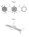
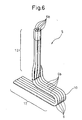
- Figs. 2 to 6 illustrate a cable harness arranged in the industrial robot according to this embodiment.
- the industrial robot 1 is an articulated robot for supporting a work piece, including a base (a linear motion part) 2 having a J1 axis as a linear motion axis, a J2 axis as a rotary motion axis and a J3 axis as a linear motion axis sequentially arranged from the base side to be subjected to the relative linear motion along the J1 axis, a body (a rotary motion part) 3 arranged vertically on the base 2 to be subjected to the relative rotary motion along the J2 axis, a cable harness 5 (Fig. 2) arranged in the base and the body 3, and equipments (not shown) such as a drive source or a controller for supplying electric power or control signals to actuators through the cable harness 5.
- a base a linear motion part 2 having a J1 axis as a linear motion axis, a J2 axis as a rotary motion axis and a J3 axis as a linear motion axis sequentially
- the base 2 is provided with a servomotor (not shown) as an actuator, a reduction unit (not shown) for reducing the rotational speed of the servomotor to increase the output torque, a ball screw (not shown) as a linear motion mechanism and a support table 2a screw-engaged with the ball screw.
- the support table 2a is linearly movable left and rightward (in the direction of J1 axis) by the rotation of the ball screw together with the motor.
- Bellows 2b are provided on both sides of the support table 2a to be extendable and shrinkable as the support table 2a moves.
- the linear motion mechanism may be formed of a rack and a pinion or belt driving mechanism.
- the support table may be directly driven by a hydraulic cylinder.
- the body 3 is fixed on the support table 2a of the base 2 via a coupling part 3a to be rotatable about a vertical motion axis (J3) and linearly movable upward and downward (in the direction of J3).
- the body 3 is driven to rotate by a servomotor (not shown) having a reduction unit and is driven to linearly move by another servomotor 4 and a ball screw (not shown).
- the motor and the reduction unit for the rotary motion are arranged within the body 3, while the motor and the reduction unit for the linear motion are arranged outside of the body 3.
- the linear motion mechanism for the body 3 may, of course, be replaced by another linear motion mechanism.
- a wrist 7 having two rotary axes J4 and J5, and a front end of the wrist 7 forms a mount 3b for an end effecter such as a hand tool.
- the specification of the end effecter varies in accordance with dimensions and shapes of a work piece to be supported by the robot 1, and is defined by the objective work piece.
- a robot arm may be provided between the wrist 7 and the end effecter.
- the cable harness 5 includes a plurality of multi-core cables 6 and electric connectors (not shown) provided at tip ends of the multi-core cables 6 and a hollow tube 10 (Fig. 3) for supplying cooling water, air or gas to an end of the end effecter, and is arranged in the interior of the base 2 and the body 3.
- the multi-core cable 6 consists of a plurality of electric power wires (umbilical elements) 8 for supplying electric power to motors of the respective axes of the robot 1 and the end effecter, and a plurality of signal lines (umbilical elements) 9 for transmitting and receiving control signals between the encoders or sensors, various controlling apparatuses and the controller (see Fig. 3).
- the outside of core wires 8a and 9a in the electric power line 8 and the signal line 9, respectively, are covered with inner coatings 8b, 9b of insulative resin.
- the plurality of electric power lines 8 and signal lines 9 are bundled to a single multi-core cable (umbilical element) 6, respectively.
- a circumference of the multi-core cable 6 formed by bundling the plurality of signal lines 9 is covered with a braided wire 6a and the outside thereof is covered with an insulative coating 6b of insulative resin.
- the braided wire 6a is formed of thin wires knitted in a lattice manner. Instead of the braided wire 6a, copper foil or others may be used as a shield member.
- the multi-core cable 6 having a plurality of signal lines 9 is subjected, as a whole, to the shield treatment to prevent the plurality of signal lines 9 from being entangled together or becoming bulkiness. Also, the handling of the cable 6 is extremely improved. By subjecting the signal lines 9 to the shield treatment, erroneous motion due to noise generated in the electronic apparatus itself is avoidable.
- the individual shielded wire consists of a core line of conductive material, an insulative inner coating covering the circumference of core line, a braided wire provided around the insulative inner coating and an insulative outer coating provided around the braided wire.
- the terminal treatment of the electromagnetically shielded cable 6 must be carried out so that the core lines 8a and 9a are not short-circuited to the braided wire 6a.
- a predetermined length of the outer coating 6b is peeled off to expose the braided wire 6a
- the inner coatings 8a and 9b covering the circumference of the core lines 8a and 9a are peeled off to expose the core lines 8a and 9a
- the braided wire 6a is folded back and grounded so that the braided wire 6a is not in contact with the core lines 8a and 9a.
- the exposed core lines 8a and 9a are crimped the terminals and accommodated in an electric connector not shown.
- a connector of a shielded type is used.
- the electric connector is a multi-pole connector accommodating a plurality of terminals in a connector housing, capable of being connected in a one-touch manner to a mating electric connector provided in the respective equipment of the robot so that the cable harness 5 is electrically connected to the respective equipment.
- the cable harness 5 will be described in more detail based on Fig. 2.
- the cable harness 5 four multi-core cables 6 and one tube (umbilical element) 10 are arranged along a path in the base 2 and the body 3 of the robot 1.
- the cables and the tube are flatly located and bonded together with soft resinous adhesive 15 to not reduce the flexibility of the cable harness 5 (see Fig. 3).
- the harness 5 becomes compact and the multi-core cables 6 are prevented from being entangled with or separated from each other.
- a plurality of electric power lines 8 and a plurality of signal lines 9 are flatly disposed to form a cable harness in the same manner as above.
- the arranged cable harness 5 includes a first bundle 12 located in the base 2 of the robot 1, a second bundle 13 located in the body 3 of the robot 1, and a third bundle 14 located in a linear motion part 3c of the body 3.
- the multi-core cables 6 and the tube 10 are flatly arranged and the adjacent ones thereof are bonded together with adhesive.
- the second bundle 13 located between the first and third bundles 12 and 14 the multi-core cables 6 and the tube 10 are individually separated from each other.
- Each of the first to third bundles 12, 13 and 14 has excessive length, wherein the excessive length in the first and third bundles is folded in a U-turn manner and the excessive length in the second bundle is bulged outside (see Fig. 4).
- the first and third bundles 12 and 14 move together with linear motion of the base 2 and the body 3, respectively, to absorb the linear displacement within the an excessive length, whereby the cable harness 5 is prevented from breaking due to the tension.
- the second bundle 13 moves together with the rotary motion of the body 3 to absorb the rotary displacement within the excessive length, whereby the cable harness 5 is prevented from breaking due to the torque.
- the individual multi-core cables 6 and the tube 10 are not bonded with adhesive but are separate from each other, they are free from the restriction caused by adjacent elements, whereby the flexibility of the second bundle 13 is facilitated to be durable against the torque.
- Fig. 4 illustrates the second bundle 13 wherein the excessive length thereof is bulged outside.
- the first and the third bundles 12 and 14 are eliminated.
- the excessive length is made to be different in the respective multi-core cables 6 so that it is larger in the multi-core cable 6 located on the outer side than that located on the inner side.
- the excessive length of the multi-core cable 6 located farther from a rotary center becomes longer, while that of the multiple-core cable 6 closer to the rotary center becomes shorter, whereby the useless excessive length is not formed and no tension is generated in the individual electric wire due to the torque during the rotary motion of the body 3.
- the cable harness 5 is inserted from one opening of a pipe member 16 to the other opening thereof so that the pipe member 16 is located on the second bundle 13 to avoid the second bundle being damaged during the rotary motion due to the contact with other parts.
- the third bundle 14 is eliminated.
- the pipe member 16 is made by cutting a metallic pipe to a predetermined length and forming a tapered section 16a in the opening into which is inserted the harness. By this tapered section 16a, the cable harness 5 is guided and smoothly inserted into the pipe member 16.
- the outer coating 6b of the individual multi-core cable 6 in the second bundle 13 is peeled off.
- the third bundle 14 is eliminated.
- the individual multi-core cable 6 becomes thinner to facilitate the flexibility of the second bundle 13, whereby the tension due to the torque is mitigated.
- the first and third bundles 12 and 14 of the cable harness 5 are formed of a plurality of multi-core cables 6 and one tube 10 flatly arranged parallel to each other and bonded together with adhesive between every adjacent elements, it is possible to make the first and third bundles 12 and 14 compact and to prevent the multi-core cables 6 and the tube 10 from being entangled with each other.
- the plurality of multi-core cables 6 and the tube 10 are separated from each other in the second bundle 13 of the cable harness 5, it is possible to facilitate the flexibility of the second bundle 13 and to enhance the durability (against torque) thereof.
- the present invention is not limited to the above-mentioned embodiment, but includes various changes and modifications.
- the industrial robot 1 according to this embodiment includes the base 2, the body 3 and the cable harness 5, an arm may be provided in the body 3 and an end-effecter is mounted to the end-effecter.
- the present invention is not limited to an industrial robot having a particular construction.
- the cable harness 5 consists of the first, second and third bundles 12, 13 and 14, it may consists of solely the first and second bundles 12 and 13, or the first and second bundles 12 and 13 may be continuously formed. That is, the cable harness may be optionally structured in accordance with the specifications of the industrial robot.
Landscapes
- Engineering & Computer Science (AREA)
- Robotics (AREA)
- Mechanical Engineering (AREA)
- Manipulator (AREA)
- Insulated Conductors (AREA)
- Electric Cable Arrangement Between Relatively Moving Parts (AREA)
Applications Claiming Priority (1)
| Application Number | Priority Date | Filing Date | Title |
|---|---|---|---|
| JP2005198762A JP2007015053A (ja) | 2005-07-07 | 2005-07-07 | 産業用ロボット |
Publications (2)
| Publication Number | Publication Date |
|---|---|
| EP1741523A2 true EP1741523A2 (de) | 2007-01-10 |
| EP1741523A3 EP1741523A3 (de) | 2007-12-26 |
Family
ID=37433821
Family Applications (1)
| Application Number | Title | Priority Date | Filing Date |
|---|---|---|---|
| EP06013829A Withdrawn EP1741523A3 (de) | 2005-07-07 | 2006-07-04 | Industrieroboter mit einem Kabelbaum |
Country Status (4)
| Country | Link |
|---|---|
| US (1) | US20070031232A1 (de) |
| EP (1) | EP1741523A3 (de) |
| JP (1) | JP2007015053A (de) |
| CN (1) | CN1891416A (de) |
Cited By (2)
| Publication number | Priority date | Publication date | Assignee | Title |
|---|---|---|---|---|
| EP2006056A1 (de) * | 2007-06-20 | 2008-12-24 | Fanuc Ltd | Industrieroboter mit einer Versorgungsleitung und einem flachen Kabel entlang eines Handgelenkteils |
| US9579806B2 (en) | 2012-08-23 | 2017-02-28 | Rethink Robotics, Inc. | Robotic power and signal distribution using laminated cable with separator webs |
Families Citing this family (21)
| Publication number | Priority date | Publication date | Assignee | Title |
|---|---|---|---|---|
| WO2006001146A1 (ja) * | 2004-06-25 | 2006-01-05 | Kabushiki Kaisha Yaskawa Denki | ポジショナおよび複合カールコード |
| KR101108767B1 (ko) * | 2006-07-11 | 2012-03-13 | 가부시키가이샤 야스카와덴키 | 다관절 로봇 및 배선 방법 |
| JP5457375B2 (ja) * | 2008-02-29 | 2014-04-02 | フスクバルナ アクティエボラーグ | 電動鋸用通信方法 |
| JP4837117B2 (ja) * | 2010-04-14 | 2011-12-14 | ファナック株式会社 | ロボットアーム部の線条体配設機構 |
| JP5346105B2 (ja) | 2012-03-27 | 2013-11-20 | ファナック株式会社 | 線条体処理装置 |
| EP2835226A1 (de) * | 2013-08-09 | 2015-02-11 | Yamaha Hatsudoki Kabushiki Kaisha | Verdrahtungsstruktur für Roboterarm |
| JP6411016B2 (ja) * | 2013-09-19 | 2018-10-24 | 蛇の目ミシン工業株式会社 | 卓上ロボット |
| CN104325466A (zh) * | 2014-11-03 | 2015-02-04 | 南京飞勒克工业设备有限公司 | 机器人管线包 |
| JP6506195B2 (ja) * | 2016-03-09 | 2019-04-24 | ファナック株式会社 | 回転軸モジュールおよび多関節ロボット |
| CN106826920B (zh) * | 2017-02-15 | 2019-05-17 | 江苏远卓电气科技有限公司 | 一种机器人机械手的束线固定装置 |
| CN107511849B (zh) * | 2017-08-31 | 2024-03-01 | 广州泰行智能科技有限公司 | 线缆的固定结构 |
| JP6870642B2 (ja) * | 2018-03-28 | 2021-05-12 | 住友電装株式会社 | 複合ケーブル対 |
| JP6644824B2 (ja) * | 2018-04-04 | 2020-02-12 | 矢崎総業株式会社 | 分岐回路体及び電線の分岐方法 |
| JP6691164B2 (ja) * | 2018-04-04 | 2020-04-28 | 矢崎総業株式会社 | 分岐回路体及び電線の分岐方法 |
| JP7135448B2 (ja) * | 2018-05-31 | 2022-09-13 | セイコーエプソン株式会社 | ロボット |
| US10836052B2 (en) * | 2019-02-06 | 2020-11-17 | Hiwin Technologies Corp. | Connection module using in robot |
| CN111098294B (zh) * | 2020-03-03 | 2021-01-01 | 冯卫 | 一种自动化生产设备用机械手 |
| CN116490328A (zh) | 2020-12-16 | 2023-07-25 | 发那科株式会社 | 动力用线束以及机器人 |
| USD1107086S1 (en) * | 2021-09-27 | 2025-12-23 | Cloudminds Robotics Co., Ltd. | Actuator |
| USD1107084S1 (en) * | 2021-09-27 | 2025-12-23 | Cloudminds Robotics Co., Ltd. | Actuator |
| USD1107083S1 (en) * | 2021-09-27 | 2025-12-23 | Cloudminds Robotics Co., Ltd. | Actuator |
Family Cites Families (9)
| Publication number | Priority date | Publication date | Assignee | Title |
|---|---|---|---|---|
| US4499341A (en) * | 1982-09-22 | 1985-02-12 | Amp Incorporated | Extensible electrical cable assembly |
| US4659279A (en) * | 1984-12-24 | 1987-04-21 | Gmf Robotics Corporation | Robot with improved cable routing and clamping |
| FR2599568B1 (fr) * | 1986-05-27 | 1988-08-26 | Afma Robots | Dispositif de guidage d'un faisceau de conducteurs soumis a une torsion. |
| JPH0221511A (ja) * | 1988-03-03 | 1990-01-24 | Sumitomo Electric Ind Ltd | 一括シールド付多芯ケーブル |
| JP2780433B2 (ja) * | 1990-05-07 | 1998-07-30 | 松下電器産業株式会社 | ロボット用ケーブルユニット |
| JPH07136974A (ja) * | 1993-11-15 | 1995-05-30 | Mitsubishi Electric Corp | ケーブルガイドの案内装置 |
| JPH08229875A (ja) * | 1994-12-02 | 1996-09-10 | Nippondenso Co Ltd | 直交座標型ロボット |
| JP2003168326A (ja) * | 2001-11-29 | 2003-06-13 | Sumitomo Wiring Syst Ltd | ケーブルハーネス |
| JP3830481B2 (ja) * | 2003-10-03 | 2006-10-04 | ファナック株式会社 | 産業用ロボット |
-
2005
- 2005-07-07 JP JP2005198762A patent/JP2007015053A/ja active Pending
-
2006
- 2006-07-04 EP EP06013829A patent/EP1741523A3/de not_active Withdrawn
- 2006-07-06 US US11/456,060 patent/US20070031232A1/en not_active Abandoned
- 2006-07-07 CN CNA2006101017490A patent/CN1891416A/zh active Pending
Cited By (4)
| Publication number | Priority date | Publication date | Assignee | Title |
|---|---|---|---|---|
| EP2006056A1 (de) * | 2007-06-20 | 2008-12-24 | Fanuc Ltd | Industrieroboter mit einer Versorgungsleitung und einem flachen Kabel entlang eines Handgelenkteils |
| US7765890B2 (en) | 2007-06-20 | 2010-08-03 | Fanuc Ltd | Industrial robot |
| US9579806B2 (en) | 2012-08-23 | 2017-02-28 | Rethink Robotics, Inc. | Robotic power and signal distribution using laminated cable with separator webs |
| US10293496B2 (en) | 2012-08-23 | 2019-05-21 | Rethink Robotics Gmbh | Robotic power and signal distribution using laminated cable with separator webs |
Also Published As
| Publication number | Publication date |
|---|---|
| CN1891416A (zh) | 2007-01-10 |
| US20070031232A1 (en) | 2007-02-08 |
| JP2007015053A (ja) | 2007-01-25 |
| EP1741523A3 (de) | 2007-12-26 |
Similar Documents
| Publication | Publication Date | Title |
|---|---|---|
| US20070031232A1 (en) | Industrial robot | |
| US20050103148A1 (en) | Cable distribution and support equipment for sensor in robot system | |
| EP1950011B1 (de) | Industrieroboter | |
| EP4064999B1 (de) | Kabelführung und anordnung für griffe von medizinprodukten | |
| CN101277006B (zh) | 基板搬运装置和电缆配线构造 | |
| CN100397532C (zh) | 具有导管机构的柔性高阻抗互连电缆 | |
| EP2719338A1 (de) | Ultraschallendoskop | |
| EP0852837B1 (de) | Anordnung für kabel mit flexibler panzerung | |
| JP2004098174A (ja) | ロボットシステムにおけるカメラ用ケーブル及び力センサ用ケーブルの配線処理構造 | |
| US20190232505A1 (en) | Robotic power and signal distribution using laminated cable with separator webs | |
| EP3958744B1 (de) | Vorrichtungen, systeme und verfahren zur positionierung von medizinischen werkzeugen | |
| US20030021557A1 (en) | Cable having signal conductors surrounding optically transmissive core remote imaging system | |
| US20030020164A1 (en) | Spherical semiconductor device and method for fabricating the same | |
| EP4119031B1 (de) | Kabelführung und anordnungen für griffe von medizinprodukten | |
| JP7135448B2 (ja) | ロボット | |
| JP2010068930A (ja) | 撮像装置、及び内視鏡 | |
| JP6898577B1 (ja) | ケーブルハーネス、ケーブルハーネスの製造方法及びケーブルハーネスを有する産業用ロボット | |
| EP1408810A2 (de) | Kabel für ein fernabbildungssystem mit um einem licht transmittierenden kern angeordneten signalleitern | |
| US20240404732A1 (en) | Multicore cable | |
| WO2022131231A1 (ja) | 動力用ハーネスおよびロボット | |
| US20250069775A1 (en) | Data and power cable assemblies | |
| JP2024169899A (ja) | 多芯ケーブル | |
| US20250255578A1 (en) | Cable routing and assemblies for medical device handles | |
| JP2025155911A (ja) | 線状物保持ブロック、線状物保持治具および装置 | |
| CN121100047A (zh) | 致动器及机器人 |
Legal Events
| Date | Code | Title | Description |
|---|---|---|---|
| PUAI | Public reference made under article 153(3) epc to a published international application that has entered the european phase |
Free format text: ORIGINAL CODE: 0009012 |
|
| AK | Designated contracting states |
Kind code of ref document: A2 Designated state(s): AT BE BG CH CY CZ DE DK EE ES FI FR GB GR HU IE IS IT LI LT LU LV MC NL PL PT RO SE SI SK TR |
|
| AX | Request for extension of the european patent |
Extension state: AL BA HR MK YU |
|
| PUAL | Search report despatched |
Free format text: ORIGINAL CODE: 0009013 |
|
| AK | Designated contracting states |
Kind code of ref document: A3 Designated state(s): AT BE BG CH CY CZ DE DK EE ES FI FR GB GR HU IE IS IT LI LT LU LV MC NL PL PT RO SE SI SK TR |
|
| AX | Request for extension of the european patent |
Extension state: AL BA HR MK YU |
|
| AKX | Designation fees paid |
Designated state(s): DE |
|
| STAA | Information on the status of an ep patent application or granted ep patent |
Free format text: STATUS: THE APPLICATION IS DEEMED TO BE WITHDRAWN |
|
| 18D | Application deemed to be withdrawn |
Effective date: 20080627 |