EP1741636A1 - Caisse empilable - Google Patents
Caisse empilable Download PDFInfo
- Publication number
- EP1741636A1 EP1741636A1 EP06008456A EP06008456A EP1741636A1 EP 1741636 A1 EP1741636 A1 EP 1741636A1 EP 06008456 A EP06008456 A EP 06008456A EP 06008456 A EP06008456 A EP 06008456A EP 1741636 A1 EP1741636 A1 EP 1741636A1
- Authority
- EP
- European Patent Office
- Prior art keywords
- box
- sidewall
- boxes
- gap
- box according
- Prior art date
- Legal status (The legal status is an assumption and is not a legal conclusion. Google has not performed a legal analysis and makes no representation as to the accuracy of the status listed.)
- Withdrawn
Links
- 239000004794 expanded polystyrene Substances 0.000 claims abstract description 10
- -1 board Substances 0.000 claims abstract description 9
- 239000000463 material Substances 0.000 claims abstract description 9
- 239000002861 polymer material Substances 0.000 claims abstract description 9
- 239000004698 Polyethylene Substances 0.000 claims description 3
- 239000004743 Polypropylene Substances 0.000 claims description 3
- 229920000573 polyethylene Polymers 0.000 claims description 3
- 229920001155 polypropylene Polymers 0.000 claims description 3
- 229920000114 Corrugated plastic Polymers 0.000 claims description 2
- 238000004519 manufacturing process Methods 0.000 abstract description 7
- 239000002184 metal Substances 0.000 abstract description 3
- 239000002023 wood Substances 0.000 abstract description 3
- 239000012620 biological material Substances 0.000 abstract description 2
- 238000009413 insulation Methods 0.000 abstract description 2
- 239000000825 pharmaceutical preparation Substances 0.000 abstract description 2
- 229940127557 pharmaceutical product Drugs 0.000 abstract description 2
- 239000000047 product Substances 0.000 abstract description 2
- 235000021067 refined food Nutrition 0.000 abstract description 2
- 239000000126 substance Substances 0.000 abstract description 2
- 230000000717 retained effect Effects 0.000 description 6
- 238000007373 indentation Methods 0.000 description 2
- 238000010276 construction Methods 0.000 description 1
- 230000000694 effects Effects 0.000 description 1
- 230000005484 gravity Effects 0.000 description 1
- 238000003898 horticulture Methods 0.000 description 1
- 238000005728 strengthening Methods 0.000 description 1
Images



Classifications
-
- B—PERFORMING OPERATIONS; TRANSPORTING
- B65—CONVEYING; PACKING; STORING; HANDLING THIN OR FILAMENTARY MATERIAL
- B65D—CONTAINERS FOR STORAGE OR TRANSPORT OF ARTICLES OR MATERIALS, e.g. BAGS, BARRELS, BOTTLES, BOXES, CANS, CARTONS, CRATES, DRUMS, JARS, TANKS, HOPPERS, FORWARDING CONTAINERS; ACCESSORIES, CLOSURES, OR FITTINGS THEREFOR; PACKAGING ELEMENTS; PACKAGES
- B65D5/00—Rigid or semi-rigid containers of polygonal cross-section, e.g. boxes, cartons or trays, formed by folding or erecting one or more blanks made of paper
- B65D5/42—Details of containers or of foldable or erectable container blanks
-
- B—PERFORMING OPERATIONS; TRANSPORTING
- B65—CONVEYING; PACKING; STORING; HANDLING THIN OR FILAMENTARY MATERIAL
- B65D—CONTAINERS FOR STORAGE OR TRANSPORT OF ARTICLES OR MATERIALS, e.g. BAGS, BARRELS, BOTTLES, BOXES, CANS, CARTONS, CRATES, DRUMS, JARS, TANKS, HOPPERS, FORWARDING CONTAINERS; ACCESSORIES, CLOSURES, OR FITTINGS THEREFOR; PACKAGING ELEMENTS; PACKAGES
- B65D21/00—Nestable, stackable or joinable containers; Containers of variable capacity
- B65D21/02—Containers specially shaped, or provided with fittings or attachments, to facilitate nesting, stacking, or joining together
Definitions
- the present invention relates to boxes, particularly boxes formed from polymer materials, especially expanded polystyrene (EPS) or other expanded polymer materials.
- EPS expanded polystyrene
- the invention is applicable to boxes generally, including those formed from cardboard, board, wood, metal, etc.
- Boxes formed from EPS or other expanded polymer materials are used in vast numbers for a huge range of purposes.
- such boxes are used generally as transport containers, for transporting all manner of goods, including (but not limited to) raw and processed food, plants (horticulture), electrical products (including "white” goods), chemical products, pharmaceutical products, and biological materials.
- Boxes (e.g. transport containers) formed from such materials have many advantages, including low manufacturing cost, thermal insulation properties, low density (and thus low overall weight), and impact resistance.
- boxes that cannot be collapsed to a flat configuration for transportation when empty suffer from the disadvantage that the cost of their transportation (when empty) is generally significant in comparison to their manufacturing cost. This is due to the amount of space occupied by the box, i.e. the relatively large volume occupied by the box compared to a box that has been collapsed flat, which means that a relatively small number of boxes can be transported in a particular volume (e.g. on a truck, or in a shipping container). For example, a typical cost of transporting an empty EPS box can be similar to the cost of manufacturing the box. Consequently, the transportation cost can significantly increase the "effective" manufacturing cost of the box (i.e. the cost of manufacturing and supplying the box).
- the present invention seeks to provide a solution to the above problems.
- the present invention seeks to provide an improved box which can overcome or ameliorate the above problems.
- a box comprising a base and an upstanding sidewall defining an interior volume of the box, the sidewall including at least one gap extending from a top edge thereof and at least one insert; whereby, in use, each gap is closed by a respective insert to provide a continuous upstanding sidewall; and, in a storage mode, each gap is operable to accept a sidewall of a corresponding mirror-image version of the box such that the sidewall of a box could be received in the gap and a portion of the upstanding wall can be received in a gap defined in a wall of said corresponding mirror-image version of the box, thereby allowing the boxes to fit together in an overlapping configuration.
- the invention has the great advantage that by the provision of one or more gaps in the sidewall of the box and the inserts removed or displaced therefrom, the sidewall of another box may be received in such gap(s), thereby allowing the boxes to fit together in an overlapping configuration (i.e. in which at least portions of the respective sidewalls overlap each other). Consequently, by means of the invention, boxes having upstanding sidewalls may be stacked together in overlapping configurations, therefore taking up less space than they would do so if stacked conventionally in a non-overlapping manner.
- mirror-image version of the box does not imply the actual presence of such a mirror-image version of the box.
- the reference merely indicates a structural fact concerning the box itself, namely that the structure of the box (i.e. a single box according to the invention) is such that if a mirror-image version of that box were present, it could be received in the gap in the sidewall of the box, thereby allowing the boxes to fit together in an overlapping configuration.
- the structure of the mirror-image version of the box is determined entirely by the structure of the box itself, and by the logical laws of symmetry.
- a second aspect of the invention provides a set of boxes comprising two (or more) boxes; in at least some embodiments of that aspect of the invention, a second box may be a mirror-image version of the first box, which mirror-image version is actually present.
- the base is unitary with the sidewall (for example, the sidewall and the base may be moulded as a unit).
- the "top edge” of the sidewall is the edge of the sidewall furthest from the base.
- the "top edge” of the sidewall may be arbitrary.
- there may be a true "top edge” of a ring extension because the ring extension may be configured to be located on the top edge of another box in a predetermined orientation.
- the "top edge” from which the gap (or gaps) extends may, or may not, be the "true” top edge.
- a second aspect of the invention provides a set of boxes comprising a first box according to the first aspect of the invention, and a second box comprising an upstanding sidewall surrounding a further interior volume of the box, the first and second boxes configured such that they are able to fit together in an overlapping configuration by the sidewall of the second box being received in at least one said gap in the sidewall of the first box.
- the set of boxes may comprise only two boxes, i.e. a pair of boxes.
- the set of boxes may comprise a plurality of pairs of boxes.
- any feature of the first aspect of the invention may be a feature of the second aspect of the invention, and vice versa.
- the second box may be a box according to the first aspect of the invention.
- the second box is a mirror-image version of the first box.
- the sidewall of the (or each) box includes only one gap.
- the sidewall may include two gaps.
- such a gap may be included in each of two faces of the sidewall, especially in each of two mutually substantially perpendicular faces of the sidewall.
- the sidewall of the box may include more than two such gaps.
- the first and second boxes are configured such that they are able to fit together in an overlapping configuration by the sidewall of the second box being received in at least one said gap in the sidewall of the first box, and by the sidewall of the first box being received in at least one said gap in the sidewall of the second box.
- the second box may be a mirror-image version of the first box, or at least have mutually corresponding walls and slots and the two boxes are of differing sizes and/or shapes, for example.
- gaps in the sidewall of only one of the boxes may receive the sidewall of the other box.
- one of the boxes may have two (or more) gaps in its sidewall, which gaps receive the sidewall of the other box.
- the other box may, or may not, itself also have one or more gaps in its sidewall.
- the gap may be formed by a flap element formed from a sidewall.
- the flap Prior to first use the flap may still be an integral part of the sidewall, retained by a hinge along one side and by perforations along the other edges of the flap and is conveniently so retained prior to being nested for the first time.
- the flap With subsequent use of the box, the flap may conveniently be taped so that it is flat with respect to the sidewall, using adhesive-backed tape to ensure that the contents of the box does not empty through the aperture or slot defined by the sidewall when the flap is open.
- An insert may be a separate member and may be configured to be slideably inserted into the gap from the top edge of the box.
- an insert may be slidable into a gap in the sidewall of the box by means of at least one protrusion and/or groove of the insert engaging with at least one respective groove and/or protrusion of the sidewall.
- Such respective sidewall and insert pairs are conveniently configured such that when the insert is inserted into the gap, it is retained in the gap against movement perpendicular to the sidewall.
- the sidewall and the insert may be configured such that when the insert is inserted into the gap, it is retained in the gap such that it substantially prevents widening of the gap due to flexing of the sidewall. Consequently, the insert in such a configuration may be securely engaged in the gap.
- a box according to the invention preferably includes a lid that is engageable with the top edge to close the box.
- a lid may not be required.
- Boxes according to the invention may advantageously be transport containers, for example. That is, the boxes may be used for transporting goods or other items, e.g. by freight or by mail (including courier delivery). However, in the broadest aspects of the invention, the boxes may be used for any purpose.
- boxes according to the invention may be formed from any material from which boxes may be constructed. For example, they may be formed from cardboard, board, wood, metal, etc. However, the invention is believed to be particularly useful for boxes formed from polymer materials, especially expanded polymer materials.
- boxes according to the invention may be formed from expanded polystyrene (EPS), but they may also be formed from expanded polypropylene (EPP), expanded polyethylene (EPE), etc.
- EPS expanded polystyrene
- EPP expanded polypropylene
- EPE expanded polyethylene
- Figure 1 (a) shows an embodiment of a box 1 according to a first aspect of the invention.
- the box 1 comprises an upstanding sidewall 3 surrounding an interior volume 5 of the box, and a base 7 from which the sidewall 3 stands.
- the base 7 and sidewall 3 are of unitary construction, for example having been moulded as a single item, e.g. from expanded polystyrene.
- boxes according to the invention can be formed from substantially any material suitable for forming boxes, but a particularly preferred material is expanded polystyrene.
- the sidewall 3 comprises four substantially flat faces 9, and the box 1 is substantially rectangular in plan view.
- a top edge 11 of the sidewall 3 includes a conventional external recess 13 extending around the entire sidewall, the recess being provided to receive a corresponding lip of a lid 15 (not shown in Figure 1, but shown in Figure 3 (a)) of the box 1.
- the recess 13 includes indentations 17, arranged to mate with corresponding protrusions (not shown) on the lip of the lid 15, to assist in the fitting of the lid to the top edge 11 of the sidewall 3 of the box 1.
- the sidewall 3 of the box includes a gap 19 extending from the top edge 11 of the sidewall.
- the gap 19 is in the form of a slot having substantially parallel sides, which slot extends from the top edge 11 almost to the base 7 of the box.
- the gap (slot) 19 has a width (along the sidewall 3) that is very slightly wider than the thickness of the sidewall (perpendicular to the sidewall). Thus, purely as an example, if the sidewall has a thickness of about 3 mm, the gap may have a width of about 3.5 mm.
- the periphery of the gap 19 i.e. an edge of the sidewall 3 defining the gap 19
- This groove 21 is arranged to receive a corresponding protrusion 23 of an insert 25 arranged to be inserted into the gap 19 substantially to close the gap and to make the sidewall substantially continuous.
- the insert 25 is shown in two enlarged views, in views (b) and (c) of Figure 1.
- the uppermost surface 27 of the insert 25 is arranged to form part of the external surface of the sidewall 3 of the box 1, when the insert is inserted into the gap 19.
- the uppermost surface 29 of the insert 25 is arranged to form part of the internal surface of the sidewall 3 of the box 1, when the insert is inserted into the gap 19.
- the protrusion 23 arranged to engage with the groove 21 in the gap 19 in the sidewall 3 of the box extends around the sides and bottom of the insert 25.
- the top region of the insert provides profiles corresponding to the recess 13, and an indentation 17, in the top edge 11 of the sidewall, thereby providing continuations of the these profiles when the insert is inserted into the gap 19 in the sidewall 3.
- the insert 25 may be inserted into the gap 19 in the sidewall 3 via the open upper end of the gap, by sliding the insert in a downwards direction from the top edge 11 of the sidewall towards the base 7 of the box, and the insert may be removed from the gap by sliding it in an opposite, upwards, direction.
- the insert When inserted into the sidewall 3, the insert is retained in place in a vertical direction by gravity and friction, and in a horizontal direction (i.e. perpendicular to the side wall) by the engagement between the protrusion 23 and the groove 21.
- a lid 15 closes the box 1 the lid also acts to retain the insert 25 in place in the gap 19.
- the, or each, such gap in the sidewall of the box comprises a slot.
- the slot preferably extends in a substantially perpendicular direction with respect to the top edge and/or with respect to a base of the box.
- the, or each, slot may be defined by substantially parallel opposite sides in the sidewall.
- the, or each, slot may taper in a direction away from the top edge, for example.
- The, or each, slot or other such gap preferably is no wider than 25% wider than the thickness of the sidewall, more preferably no wider than 10% wider than the thickness of the sidewall, so that when a sidewall of a similar or identical box is received in the gap, preferably the fit is close or moderately close.
- This has the advantage of providing stability or rigidity to the fitted together boxes, for example so that if they are stacked with other pairs of boxes, the entire stack preferably has at least reasonable stability. It also has the advantage that preferably a pair of boxes fitted together in an overlapping manner according to the invention can be handled substantially as a unit, thereby facilitating their handling.
- the sidewall may include a relatively thick region (relative to the rest of the sidewall) in which a gap (e.g. a slot) is provided. This has the advantage of strengthening the sidewall in the region of the gap.
- the underside of the base of each box may be profiled to engage with a corresponding underside of a base of another box, to reduce the possibility of relative lateral movement between two boxes stacked base-to-base.
- the profiling of the underside of the base of a box may comprise one or more protrusions (e.g. one or more "dimples") and/or one or more recesses (e.g. one or more hollows corresponding to a respective dimple).
- the, or each, gap in a sidewall of a box according to the invention has a depth of at least 25% of the height of the sidewall. More preferably, the, or each, such gap has a depth of at least 50%, especially at least 75%, of the height of the sidewall. In some preferred embodiments of the invention, the, or each, such gap has a depth of substantially the entire height of the sidewall.
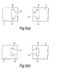
- the groove 21 in the periphery of the gap 19 may have a shape such as that shown in Figure 5 (a) or Figure 5 (b) (or a similar shape).
- the grooves 31 and 33 shown in Figure 5 are arranged to engage with a respective corresponding protrusion (not shown) of an insert. Because the grooves 31 and 33 include regions 35 that are wider than their openings 37, an insert that engages with such grooves will substantially prevent any widening of the gap 19.
- Figure 2 shows two embodiments of a set of boxes (in fact, two pairs of boxes) according to the invention.
- one of the boxes comprises a box 1 according to the invention, having two gaps 19 in its sidewall 3, whereas the other box 37 is not a box according to the invention (although it is box of a set of boxes according to the invention) because the box 37 does not have any gaps 19 in its sidewall 3.
- the gaps 19 are situated in respective mutually perpendicular faces of the sidewall 3, adjacent to opposite corners 39 of the box 1.
- One of the gaps 19 is identical to that shown in Figure 1 (i.e. including a groove 21), whereas the other gap 19 is shown without any such groove, for simplicity.
- the boxes 1 and 37 shown in Figure 2 each have four substantially flat faces, and are generally rectangular in plan view.
- each box 1 in Figure 2 The two gaps 19 of each box 1 in Figure 2 are shown open (i.e. they are not closed by inserts 25).
- the conventional box 37 and the novel box 1 may be fitted together in an overlapping configuration, by inverting one of the boxes (in the figure, box 1 is inverted, but box 37 could be inverted instead) and by causing the sidewall of box 37 to be received in the gaps 19 in the sidewall 3 of box 1. It is clearly seen from view (b) of Figure 2, that the volume occupied by the two boxes fitted together in this overlapping manner is significantly less than would be the case if the boxes were simply stacked with one on top of the other (which would be the case in the absence of the present invention).
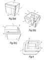
- the box 1 may include only a single gap 19 in its sidewall 3, for example as shown in Figure 3.
- the boxes shown in Figure 3 are similar to the box shown in Figure 1, and the same reference numerals indicate corresponding features.
- the box 1 may be fitted together with another box 1 according to the invention, which other box 1 is a mirror-image version of the box 1.
- Figure 3 (c) in which two boxes 1 according to the invention, which are mirror-images of each other, are fitted together with the sidewall 3 of each box received in the gap 19 of the other box.
- the gap 19 in one of the boxes is shown, whereas the gap 19 in the other box is hidden, but its location is indicated by an arrow.
- Figure 3 (c) thus illustrates a set of two boxes according to the invention, which boxes are mirror-image versions of each other, and Figure 3 (c) also provides an illustration of how a box according to the invention could (in a virtual, or imaginary way) be fitted together with its own mirror-image.
- the sidewall of a box according to the invention can have any thickness, but for most boxes the sidewall will have a thickness in the range of 2 mm to 150 mm, preferably in the range of 5 mm to 100m.
- some "standard" wall thicknesses include: 22 mm; 25 mm; 35 mm; 40 mm; 50 mm; and 65 mm.
- the box further comprises an element having a sidewall without a base or comprises one of a pair wherein, each continuous sidewall of a pair has corresponding gaps, each gap extending partially in relation to the height of the sidewall, wherein the gaps are appropriately spaced to enable stacking.
- the box may be a so-called "ring" extension, for example, which can be located on the top edge of another box having a base (or indeed on another ring extension which itself is located on a box with a base, or on another ring extension).
- ring extensions are used to increase the depth of a box in a versatile manner.
- Figure 4 shows a further set of boxes according to the invention, which boxes are fitted together in an overlapping configuration.
- box 41 comprises only a sidewall 3, and does not include a base 7.
- Box 41 may, for example, comprise a ring-extension, e.g. as described above.
- Figure 6 shows the box 60 with uppermost flaps 62, 63 extending parallel with a base to form a closed box.
- Dashed line 64 indicates a flex-portion about which flap 65 can hinge about flex or otherwise depend, as can be clearly seen with reference to Figure 7, which shows the box with uppermost flaps depending downwardly, within the box and with flap 65 in an open position, whereby a mirror image version may be placed upon, whereby to enable nesting thereof. It will be appreciated, that in this version, there is no separate lid.
- the edges of the flap not being the hinge with sidewall 66, and as indicated by dotted lines 67 are either heavily perforated to enable convenient opening of the flap about the hinge.
- the flap may be taped together using adhesive-backed tape. If manufactured from, for example cardboard or corrugated plastics/cardboard or other material, the thickness of the sidewalls may be 1 - 10 mm or more.
- the sidewalls of the boxes are conveniently rectilinear in plan view, but may be of a generally circular or elliptical shape and boxes according to the invention may generally be of any type having an upstanding sidewall.
- the sidewall may be curved (e.g. the box may be substantially cylindrical, or may have a curved sidewall defining another shape).
- the sidewall will comprise a plurality of substantially flat faces, e.g. four substantially flat faces.
- the box may be substantially square or rectangular in plan view.
- the sidewall comprises a plurality of faces, and therefore comprises a plurality of corners between faces, preferably any gap (e.g.
- slot) in the sidewall is located at, or adjacent to, a respective corner.
- This has the advantage that when boxes are fitted together, they will be overlapped (in plan view) to the maximum extent possible, thereby saving the greatest amount of space (in a lateral direction).
- the gaps will conveniently be arranged in an oblique fashion with respect to the wall, in the area of the wall.
Landscapes
- Engineering & Computer Science (AREA)
- Mechanical Engineering (AREA)
- Stackable Containers (AREA)
Applications Claiming Priority (1)
| Application Number | Priority Date | Filing Date | Title |
|---|---|---|---|
| GBGB0514151.0A GB0514151D0 (en) | 2005-07-09 | 2005-07-09 | Box |
Publications (1)
| Publication Number | Publication Date |
|---|---|
| EP1741636A1 true EP1741636A1 (fr) | 2007-01-10 |
Family
ID=34897014
Family Applications (1)
| Application Number | Title | Priority Date | Filing Date |
|---|---|---|---|
| EP06008456A Withdrawn EP1741636A1 (fr) | 2005-07-09 | 2006-04-24 | Caisse empilable |
Country Status (3)
| Country | Link |
|---|---|
| US (1) | US20070007160A1 (fr) |
| EP (1) | EP1741636A1 (fr) |
| GB (1) | GB0514151D0 (fr) |
Families Citing this family (2)
| Publication number | Priority date | Publication date | Assignee | Title |
|---|---|---|---|---|
| US10975704B2 (en) | 2018-02-19 | 2021-04-13 | General Electric Company | Engine component with cooling hole |
| US10563519B2 (en) | 2018-02-19 | 2020-02-18 | General Electric Company | Engine component with cooling hole |
Citations (3)
| Publication number | Priority date | Publication date | Assignee | Title |
|---|---|---|---|---|
| FR2527172A1 (fr) * | 1982-05-24 | 1983-11-25 | Palmason Jon | Recipient ouvert vers le haut |
| WO1993011048A1 (fr) * | 1991-12-06 | 1993-06-10 | Beekenkamp Tuinbouwtechniek B.V. | Recipient emboitable |
| WO2002072436A1 (fr) * | 2001-03-13 | 2002-09-19 | Martin Riedi | Ensemble de conteneurs de produits |
-
2005
- 2005-07-09 GB GBGB0514151.0A patent/GB0514151D0/en not_active Ceased
-
2006
- 2006-04-24 EP EP06008456A patent/EP1741636A1/fr not_active Withdrawn
- 2006-04-28 US US11/413,537 patent/US20070007160A1/en not_active Abandoned
Patent Citations (3)
| Publication number | Priority date | Publication date | Assignee | Title |
|---|---|---|---|---|
| FR2527172A1 (fr) * | 1982-05-24 | 1983-11-25 | Palmason Jon | Recipient ouvert vers le haut |
| WO1993011048A1 (fr) * | 1991-12-06 | 1993-06-10 | Beekenkamp Tuinbouwtechniek B.V. | Recipient emboitable |
| WO2002072436A1 (fr) * | 2001-03-13 | 2002-09-19 | Martin Riedi | Ensemble de conteneurs de produits |
Also Published As
| Publication number | Publication date |
|---|---|
| GB0514151D0 (en) | 2005-08-17 |
| US20070007160A1 (en) | 2007-01-11 |
Similar Documents
| Publication | Publication Date | Title |
|---|---|---|
| EP3464095B1 (fr) | Récipient de vrac empilable | |
| US9637302B2 (en) | Economically improved plastic bottle and package system | |
| US8403144B2 (en) | Liquid container: system for distribution | |
| US8066149B2 (en) | Stackable container with support structure | |
| US3907111A (en) | Self-cleaning stackable container | |
| US20100206759A1 (en) | Stackable liquid container with tunnel-shaped base | |
| US20090152158A1 (en) | Carrier tray | |
| CA2879015C (fr) | Intercalaire de rangee sans compartiment | |
| US7467714B2 (en) | Container stack and separating element therefor | |
| KR20160148506A (ko) | 용기 장치 | |
| US3478867A (en) | Stackable trays and package formed therefrom | |
| JP2010111401A (ja) | 運搬用容器 | |
| US3926363A (en) | Stacking trays and container for persihable items | |
| US7967142B2 (en) | Nestable crate | |
| US10227157B2 (en) | Egg carton with diagonal lid panel | |
| US10889406B2 (en) | System of open-topped containers | |
| RU120948U1 (ru) | Ящик для продуктов (варианты) и штабель из таких ящиков | |
| EP1741636A1 (fr) | Caisse empilable | |
| CN108698732B (zh) | 用于管件运输的托盘 | |
| WO2015140272A1 (fr) | Plateau de chargement | |
| US3722735A (en) | Stackable and nestable container | |
| CA2779463A1 (fr) | Cageot a volaille | |
| KR200298028Y1 (ko) | 포장 박스 내부에 들어가는 골판지를 이용한 적층 포장체 | |
| JP4282875B2 (ja) | 運搬用容器 | |
| CA2697429C (fr) | Contenant a liquide : systeme et methode de distribution connexe |
Legal Events
| Date | Code | Title | Description |
|---|---|---|---|
| PUAI | Public reference made under article 153(3) epc to a published international application that has entered the european phase |
Free format text: ORIGINAL CODE: 0009012 |
|
| AK | Designated contracting states |
Kind code of ref document: A1 Designated state(s): AT BE BG CH CY CZ DE DK EE ES FI FR GB GR HU IE IS IT LI LT LU LV MC NL PL PT RO SE SI SK TR |
|
| AX | Request for extension of the european patent |
Extension state: AL BA HR MK YU |
|
| 17P | Request for examination filed |
Effective date: 20070316 |
|
| 17Q | First examination report despatched |
Effective date: 20070518 |
|
| AKX | Designation fees paid |
Designated state(s): AT BE BG CH CY CZ DE DK EE ES FI FR GB GR HU IE IS IT LI LT LU LV MC NL PL PT RO SE SI SK TR |
|
| STAA | Information on the status of an ep patent application or granted ep patent |
Free format text: STATUS: THE APPLICATION IS DEEMED TO BE WITHDRAWN |
|
| 18D | Application deemed to be withdrawn |
Effective date: 20080807 |