EP1741879B1 - Vorrichtung zur Abstützung und Einlassung von Röhre und Kabeln in einem Turbotriebwerk - Google Patents
Vorrichtung zur Abstützung und Einlassung von Röhre und Kabeln in einem Turbotriebwerk Download PDFInfo
- Publication number
- EP1741879B1 EP1741879B1 EP06076291A EP06076291A EP1741879B1 EP 1741879 B1 EP1741879 B1 EP 1741879B1 EP 06076291 A EP06076291 A EP 06076291A EP 06076291 A EP06076291 A EP 06076291A EP 1741879 B1 EP1741879 B1 EP 1741879B1
- Authority
- EP
- European Patent Office
- Prior art keywords
- radial
- detachable panel
- arm
- along
- panel
- Prior art date
- Legal status (The legal status is an assumption and is not a legal conclusion. Google has not performed a legal analysis and makes no representation as to the accuracy of the status listed.)
- Active
Links
Images


Classifications
-
- F—MECHANICAL ENGINEERING; LIGHTING; HEATING; WEAPONS; BLASTING
- F02—COMBUSTION ENGINES; HOT-GAS OR COMBUSTION-PRODUCT ENGINE PLANTS
- F02K—JET-PROPULSION PLANTS
- F02K3/00—Plants including a gas turbine driving a compressor or a ducted fan
- F02K3/02—Plants including a gas turbine driving a compressor or a ducted fan in which part of the working fluid by-passes the turbine and combustion chamber
- F02K3/04—Plants including a gas turbine driving a compressor or a ducted fan in which part of the working fluid by-passes the turbine and combustion chamber the plant including ducted fans, i.e. fans with high volume, low pressure outputs, for augmenting the jet thrust, e.g. of double-flow type
-
- F—MECHANICAL ENGINEERING; LIGHTING; HEATING; WEAPONS; BLASTING
- F01—MACHINES OR ENGINES IN GENERAL; ENGINE PLANTS IN GENERAL; STEAM ENGINES
- F01D—NON-POSITIVE DISPLACEMENT MACHINES OR ENGINES, e.g. STEAM TURBINES
- F01D9/00—Stators
- F01D9/06—Fluid supply conduits to nozzles or the like
- F01D9/065—Fluid supply or removal conduits traversing the working fluid flow, e.g. for lubrication-, cooling-, or sealing fluids
Definitions
- the present invention relates to a device for supporting and accommodating servitudes in a turbofan engine, this device comprising two coaxial ferrules arranged one inside the other and connected by tubular radial arms in which ducts pass. of fluid and electrical cables.
- This device is mounted around a turbojet compressor, downstream of the fan and upstream of a turbojet turbine, and can cooperate by its outer shell with a thrust reverser, mounted downstream of this device.
- the inner and outer shrouds of the device delimit between them an annular flow stream of the secondary flow which comes from the turbojet engine fan and which is particularly intended for cooling components of the turbojet engine.
- the radial arms of this device are monobloc and the inner shell comprises panels in cylinder portion (extending for example over 90 °) which are fixed by screws on a support bracket and which can be disassembled. to allow access to equipment installed on the outer casing of the compressor, for a maintenance operation.
- This technique does not, however, allow access to equipment located inside the inner shell and in the alignment of the radial arms and which are for example of the type LRU (English Line Replaceable Unit) such as cylinders controlling the angular setting of the rectifiers of the compressor, which must be dismountable without disassembly of the ferrules of the service support device.
- LRU English Line Replaceable Unit
- the invention aims in particular to provide a simple, effective and economical solution to the problems of the current technique.
- a support and housing servitudes in a turbofan engine comprising two coaxial ferrules arranged one inside the other and connected by tubular radial arms in which fluid conduits and electrical cables pass, characterized in that one face side of at least one radial arm comprises a removable panel having a radial portion attached to the radial arm and a cylindrical portion connecting to the inner ring.
- the radial arms located above the turbojet equipment subject to maintenance operations each comprise on one of their lateral faces a removable panel which is fixed by screws or the like on the radial arm.
- the equipment maintenance operations located in the alignment of the radial arms are thus easier to perform and can be performed directly on a turbojet engine mounted under the wing of an aircraft.
- Removal of the removable panels of the radial arms allows access to turbojet equipment located radially inside the inner shell in the alignment of the radial arm, improves access and visibility of equipment, facilitates the use of tools for disassembly and maintenance of this equipment, and allows the removal of certain equipment for their replacement.
- the radial portion of the removable panel is laid and secured along at least some of its edges on corresponding flanges of the radial arm and the cylindrical portion of this removable panel is placed and secured along at least some its edges on corresponding edges of the inner shell.
- the circumferential dimension of the circumferential portion of this duct is advantageously less than that of the cylindrical portion of the removable panel of the radial arm in order to access this duct and extract it if necessary from the inside the inner shell.
- This fluid duct is, for example, a hot air circulation duct, one end of which opens into a compressor of the turbojet engine for the extraction of air and the other end of which is fixed to the outer shell and is connected to circulation means. of fluid.
- the device also comprises sealing means such as tight joints between the removable panel and the radial arm and / or between the removable panel and the inner shell.
- the device comprises two radial arms diametrically opposed with respect to the axis of the ferrules and each comprising a removable panel for access to equipment located inside the inner shell, this equipment being for example a cylinder of the type LRU variable-pitch rectifier control.
- the invention also relates to a device of the type described above, the removable panel being characterized in that it is substantially L-shaped and comprises a radial flat plate connected to a curved plate in an arc of a circle, this panel comprising a series of bolt holes along at least one of its longitudinal edges and along the end edge of the curved plate.
- This removable panel is preferably equipped with seals along the edges of its radial and curved plates.
- FIG. 1 a device 10 according to the invention for supporting and accommodating servitudes in a turbofan engine, this device comprising two coaxial cylindrical shells 12, 14 which extend one around the other and which are interconnected by radial arms 16, 18, 20 and 22, some of these arms 16, 18 having a removable side panel 24, 26 allowing access to turbojet equipment located inside the inner shell and at least partly in the radial arm alignment, for a maintenance operation.
- This device is mounted downstream of the turbojet engine fan and the inner shell 12 surrounds an outer casing of the turbojet compressor, at a distance from this casing, and extends axially in alignment with another casing of the turbojet engine.
- the inner shell 12 delimits with the outer shell 14 an annular flow stream of the secondary stream from the fan which is schematically represented by arrows.
- the outer shell 14 comprises at its upstream and downstream ends external annular rims 28 for attachment by means appropriate to a intermediate casing of the turbojet engine and a thrust reverser, respectively.
- the outer shell 14 ensures the transmission of forces between the intermediate casing and the thrust reverser, the latter being for example of the door type.
- the radial arms 16, 18, 20, 22 are four in number in the example shown.
- Two of these radial arms 16, 18 are diametrically opposed relative to the axis A of the device and extend substantially in a vertical plane.
- the upper arm 16 is called “arm 12h” and the lower arm 18 is called “arm 6h”, by analogy with the dial of a watch, and the other two radial arms 20, 22 are located on either side of the lower arm 18, about 60 ° thereof, and are called “arm 4h” and "arm 8h”.
- These arms 16, 18, 20, 22 are tubular and open at their inner and outer ends so that components located radially inside and outside the device can be connected to fluid conduits and electrical cables passing through. inside the arms.
- electrical cables pass inside the arm 20
- a fuel pipe passes inside the arm 22
- an oil duct passes inside the arm 18
- an air duct passes to the inside. inside the arm 16.
- Another air duct 23 comprises a nozzle mounted on a downstream portion of the upper arm 16 and extending substantially parallel to the axis A of the device. This duct is connected upstream to means for withdrawing air from the secondary flow and downstream to appropriate air circulation means for cooling components of the turbojet engine and supplying air to the flight control cabin. airplane equipped with this turbojet engine.
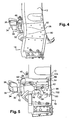
- the upper radial arms 16 and lower 18 each comprise a side panel 24, 26 removable and allowing access to components which are mounted on the housing (not shown) of the compressor and which is in alignment with the radial arm.
- the removable panel 24 of the arm 16 is substantially L-shaped and comprises a flat plate 50 intended to extend radially on the side of the arm 16 to close it, and connected at its inner end to a plate 52 curved in a circular arc which forms part of the inner shell 12 adjacent to the arm.
- the plate 50 is placed and fixed by means of screws 54 along its upstream and downstream edges on corresponding radial flanges 56, 58 which extend along the upstream and downstream lateral edges 62 of the arm 16, respectively ( figure 3 ).
- the plate 52 is placed and fixed by means of screws 54 along its upstream edge and its lateral end opposite the arm 16, respectively on a circumferential rim 64 which extends along the upstream end of the shell 12 and on an axial flange 66 which extends from upstream to downstream on the ferrule.
- the circumferential flange 64 for supporting the plate 52 connects the axial flange 66 to the upstream radial rim 56 of the arm 16.
- the axial flange 66 of the shell 12 comprises on its outer surface an axial groove 70 in which is housed a seal (not shown).
- This seal is intended to be clamped between the flange 60 of the ferrule and the plate 24 in order to avoid, on the one hand, the passage of air of the secondary flow radially inside the inner ferrule and, on the other hand, the propagation a possible fire occurring in the turbojet radially outwardly in the secondary flow.
- the removable panel 26 of the arm 18 is also L-shaped and its size is smaller than that of the panel 24.
- the panel 26 comprises a flat plate 90 which extends radially on the side of the arm 18 substantially at half height thereof and which is connected to a plate 92 curved in an arc which extends over the inner shell 12 .
- the plate 90 is placed and fixed by screws 94 along its edge radially outer and its upstream edge on corresponding flanges 96, 98 of the arm, respectively.
- the flange 96 extends axially from upstream to downstream along the radially inner side edge 100 of the arm, and the flange 98 extends radially along the upstream lateral edge 102 of the arm.
- the plate 92 is placed and fixed on flanges 64, 66 of the ferrule, as previously described for the plate 52 with reference to the figure 3 .
- a seal (not shown) is housed in an axial groove 104 of the flange 66 of the ferrule and clamped between this flange 66 and the plate 26. Seals may also be provided in grooves of the axial flange 96 of the ferrule 66. arm and circumferential edge 64 of the ferrule 12.
- the removal of the panels 24, 26 of the arms 16, 18 makes it possible to carry out maintenance operations on cylinders 30 and a fluid conduit 72 which are mounted on the compressor casing in the alignment or near the arms 16, 18.
- the jacks 30 extend upstream substantially parallel to the axis A of the device.
- the body 32 of each jack is carried by a tab 34 fixed by means of screws 36 or the like on the compressor housing.
- the piston rod 38 of each cylinder is connected to a mechanism 40 of angular setting compressor rectifiers, by a link 42 whose one end is integral in rotation with the mechanism 40 and whose other end is articulated on the piston rod 36 by a screw-nut type system 44 or the like.
- the mechanism 40 is fixed to the casing by screws 46 and connected by appropriate means 48 to control rings (not shown) which surround the compressor casing and which are displaceable in rotation about the axis of the turbojet engine to drive into position. rotating the rectifiers of the compressor around their axes.
- An air duct 72 passes inside the arm 16 and comprises a radially inner end fixed on the compressor housing and opening into the compressor for the hot air sampling, and a radially outer end fixed to the outer shell 14 and connected to another duct 74 for supplying air for example to the nacelle of the turbojet engine for deicing.
- the conduit 72 extends radially from its outer end fixed on the outer shell 14 to a connecting bend 76 to a circumferential portion 78 of the conduit which extends inside the inner shell 12 along and near circumferential rim 64 of the ferrule 12.
- the end of the portion 78 of the conduit opposite the arm 16 is connected by another bend 80 to an axial portion 82 of the duct which extends downstream and which is connected at its downstream end to a bend 84 which includes its free end a fixing flange 86 by means of screws 88 on the compressor housing.
- Removing the removable panel 24 also allows access to the screws 86 for fixing the conduit 72 for disassembly.
- the circumferential dimension of the curved plate 52 of the panel 24 is greater than that of the portion 78 of the conduit 72 to facilitate the extraction of the conduit.
Landscapes
- Engineering & Computer Science (AREA)
- Mechanical Engineering (AREA)
- General Engineering & Computer Science (AREA)
- Chemical & Material Sciences (AREA)
- Combustion & Propulsion (AREA)
- Physics & Mathematics (AREA)
- Fluid Mechanics (AREA)
- Structures Of Non-Positive Displacement Pumps (AREA)
Claims (9)
- Vorrichtung zum Stützen und Aufnehmen von Hilfsgeräten in einem Zweikreisstrahltriebwerk mit zwei koaxialen Zwingen (12, 14), die in einander angeordnet und durch radiale rohrförmige Arme (16, 18, 20, 22) verbunden sind, in denen Fluidleitungen (72) und Stromkabel verlaufen, dadurch gekennzeichnet, daß eine Seitenfläche wenigstens eines radialen Arms (16, 18) ein abnehmbares Feld (24, 26) mit einem radialen Teil, der an dem radialen Arm (16, 18) befestigt ist, und einem zylindrischen Teil zum Anschluß an die innere Zwinge (12) aufweist.
- Vorrichtung nach Anspruch 1, dadurch gekennzeichnet, daß der radiale Teil des abnehmbaren Feldes (24, 26) entlang wenigstens bestimmter seiner Ränder an entsprechende Kanten (56, 58, 96, 98) des radialen Arms (16, 18) gesetzt und dort befestigt ist und der zylindrische Teil des abnehmbaren Feldes (24, 26) entlang wenigstens bestimmter seiner Ränder an entsprechende Kanten (64, 66) des radialen Arms (16, 18) gesetzt und dort befestigt ist.
- Vorrichtung nach einem der vorhergehenden Ansprüche, dadurch gekennzeichnet, daß sie Dichtungsmittel wie Dichtungen aufweist, die zwischen das abnehmbare Feld (24, 26) und den radialen Arm (16, 18) und/oder zwischen das abnehmbare Feld (24, 26) und die innere Zwinge (12) eingeklemmt sind.
- Vorrichtung nach einem der vorhergehenden Anspruche, dadurch gekennzeichnet, daß sich eine Fluidleitung (72) im wesentlichen radial in dem radialen Arm (16) entlang des abnehmbaren Feldes (24) und im wesentlichen umfangsmäßig im Inneren der inneren Zwinge (12) erstreckt, wobei die Umfangsabmessung des Umfangsteils (78) dieser Leitung (72) kleiner als die Umfangsabmessung des zylindrischen Teils des abnehmbaren Feldes (24) ist.
- Vorrichtung nach Anspruch 4, dadurch gekennzeichnet, daß die Fluidleitung (72) eine Heißluftzirkulationsleitung ist, von welcher ein Ende in einen Verdichter des Strahltriebwerks für die Entnahme von Luft mündet und von welcher das andere Ende an der äußeren Zwinge (14) befestigt und mit Fluidzirkulationsmitteln verbunden ist.
- Vorrichtung nach einem der vorhergehenden Ansprüche, dadurch gekennzeichnet, daß sie zwei bezüglich der Achse (A) der Zwingen (12, 14) diametral entgegengesetzte radiale Arme (16, 18) aufweist, die jeweils ein abnehmbares Feld zum Zugang zu einem Gerät (30) aufweisen, das im Inneren der inneren Zwinge (12) liegt.
- Vorrichtung nach einem der vorhergehenden Ansprüche, dadurch gekennzeichnet, daß das durch Abbau des abnehmbaren Feldes (24, 26) zugängliche Gerät ein Zylinder (30) zum Steuern von Leitapparaten mit variabler Einstellung ist.
- Vorrichtung nach einem der vorhergehenden Ansprüche, dadurch gekennzeichnet, daß das abnehmbare Feld (24, 26) im wesentlichen L-förmig ist und eine radiale ebene Platte (50, 90) aufweist, die an eine kreisbogenförmig gekrümmte Platte (52, 92) angeschlossen ist, wobei dieses Feld (24, 26) eine Reihe von Löchern zum Durchgang von Schrauben entlang wenigstens eines ihrer Längsränder und entlang des Endrandes der gekrümmten Platte aufweist.
- Vorrichtung nach Anspruch 8, dadurch gekennzeichnet, daß das abnehmbare Feld (24, 26) Dichtungen entlang der Ränder seiner radialen (50, 90) und gekrümmten (52, 92) Platte aufweist.
Applications Claiming Priority (1)
| Application Number | Priority Date | Filing Date | Title |
|---|---|---|---|
| FR0506612A FR2887931B1 (fr) | 2005-06-29 | 2005-06-29 | Dispositif de support et de logement de servitudes dans un turboreacteur a double flux |
Publications (2)
| Publication Number | Publication Date |
|---|---|
| EP1741879A1 EP1741879A1 (de) | 2007-01-10 |
| EP1741879B1 true EP1741879B1 (de) | 2009-01-28 |
Family
ID=35929691
Family Applications (1)
| Application Number | Title | Priority Date | Filing Date |
|---|---|---|---|
| EP06076291A Active EP1741879B1 (de) | 2005-06-29 | 2006-06-23 | Vorrichtung zur Abstützung und Einlassung von Röhre und Kabeln in einem Turbotriebwerk |
Country Status (5)
| Country | Link |
|---|---|
| US (1) | US7805949B2 (de) |
| EP (1) | EP1741879B1 (de) |
| DE (1) | DE602006005027D1 (de) |
| FR (1) | FR2887931B1 (de) |
| RU (1) | RU2324832C2 (de) |
Families Citing this family (24)
| Publication number | Priority date | Publication date | Assignee | Title |
|---|---|---|---|---|
| US20060032974A1 (en) * | 2004-08-16 | 2006-02-16 | Honeywell International Inc. | Modular installation kit for auxiliary power unit |
| US20080078162A1 (en) * | 2006-09-28 | 2008-04-03 | Guy Lefebvre | Turbine exhaust case cowling for a gas turbine engine |
| FR2932233B1 (fr) * | 2008-06-06 | 2012-09-28 | Aircelle Sa | Carter pour rotor de turbomachine |
| FR2933130B1 (fr) * | 2008-06-25 | 2012-02-24 | Snecma | Carter structural pour turbomachine |
| US9121351B2 (en) * | 2008-10-30 | 2015-09-01 | Rolls-Royce North American Technologies, Inc. | Gas turbine engine accessory system |
| US8966911B2 (en) * | 2009-12-29 | 2015-03-03 | Rolls-Royce North American Technologies, Inc. | Turbofan engine with HP and LP power off-takes |
| GB2497807B (en) | 2011-12-22 | 2014-09-10 | Rolls Royce Plc | Electrical harness |
| US9478896B2 (en) | 2011-12-22 | 2016-10-25 | Rolls-Royce Plc | Electrical connectors |
| GB2497809B (en) | 2011-12-22 | 2014-03-12 | Rolls Royce Plc | Method of servicing a gas turbine engine |
| GB2498006B (en) | 2011-12-22 | 2014-07-09 | Rolls Royce Plc | Gas turbine engine systems |
| GB201306482D0 (en) * | 2013-04-10 | 2013-05-22 | Rolls Royce Plc | Mounting arrangement |
| FR3005992B1 (fr) * | 2013-05-24 | 2015-05-22 | Snecma | Dispositif de passage de servitudes pour une turbomachine |
| FR3008912B1 (fr) * | 2013-07-29 | 2017-12-15 | Snecma | Carter de turbomachine et procede de fabrication |
| FR3010049B1 (fr) * | 2013-09-04 | 2017-03-31 | Snecma | Structure de liaison moteur-nacelle a secteurs de virole pivotants |
| FR3015625B1 (fr) * | 2013-12-20 | 2015-12-11 | Snecma | Bras de guidage d'elements de forme allongee, en particulier pour une turbomachine |
| US10858950B2 (en) | 2017-07-27 | 2020-12-08 | Rolls-Royce North America Technologies, Inc. | Multilayer abradable coatings for high-performance systems |
| US10900371B2 (en) | 2017-07-27 | 2021-01-26 | Rolls-Royce North American Technologies, Inc. | Abradable coatings for high-performance systems |
| FR3077846B1 (fr) * | 2018-02-14 | 2020-03-13 | Safran Aircraft Engines | Virole exterieure de carter intermediaire pour turbomachine d'aeronef a double flux, comprenant des dispositifs ameliores d'etancheite a l'air et de resistance au feu |
| GB201808853D0 (en) * | 2018-05-31 | 2018-07-18 | Rolls Royce Plc | A gas turbine engine bleed duct |
| GB201808852D0 (en) | 2018-05-31 | 2018-07-18 | Rolls Royce Plc | Gas turbine engine |
| FR3096743B1 (fr) | 2019-05-28 | 2021-05-07 | Safran Aircraft Engines | Paroi coupe-feu et procédé d’ouverture de celle-ci |
| US11047251B2 (en) | 2019-07-17 | 2021-06-29 | Rolls-Royce Corporation | Routing for electrical communication in gas turbine engines |
| FR3117173B1 (fr) | 2020-12-09 | 2025-03-28 | Safran Aircraft Engines | Ensemble propulsif d’aéronef et procédé d’adaptation d’un ensemble propulsif |
| FR3167628A1 (fr) * | 2024-10-18 | 2026-04-24 | Airbus Operations | Ensemble de propulsion comprenant au moins un boîtier de protection configuré pour loger au moins un tronçon d’un élément longiligne comme un câble électrique |
Family Cites Families (15)
| Publication number | Priority date | Publication date | Assignee | Title |
|---|---|---|---|---|
| US2827760A (en) * | 1951-04-18 | 1958-03-25 | Bristol Aero Engines Ltd | Combined anti-icing and generator cooling arrangement for a gas turbine engine |
| US3571977A (en) * | 1969-06-27 | 1971-03-23 | Boeing Co | Access and pressure release door latch mechanism |
| US3777489A (en) * | 1972-06-01 | 1973-12-11 | Gen Electric | Combustor casing and concentric air bleed structure |
| US5012639A (en) * | 1989-01-23 | 1991-05-07 | United Technologies Corporation | Buffer region for the nacelle of a gas turbine engine |
| US5123242A (en) * | 1990-07-30 | 1992-06-23 | General Electric Company | Precooling heat exchange arrangement integral with mounting structure fairing of gas turbine engine |
| GB2267736B (en) * | 1992-06-09 | 1995-08-09 | Gen Electric | Segmented turbine flowpath assembly |
| US5292227A (en) * | 1992-12-10 | 1994-03-08 | General Electric Company | Turbine frame |
| RU2056544C1 (ru) * | 1993-02-11 | 1996-03-20 | Акционерное общество "Авиадвигатель" | Статор компрессора высокого давления |
| US6012735A (en) * | 1994-06-13 | 2000-01-11 | Textron Automotive Company | Trim panel having air bag door |
| EP1320488A2 (de) * | 2000-09-27 | 2003-06-25 | Lord Corporation | Befestigungsvorrichtung eines hilfsaggregats (apu) in einem flugzeug |
| US6942452B2 (en) * | 2002-12-17 | 2005-09-13 | Pratt & Whitney Canada Corp. | Grommeted bypass duct penetration |
| GB0315894D0 (en) * | 2003-07-08 | 2003-08-13 | Rolls Royce Plc | Aircraft engine arrangement |
| US7083144B2 (en) * | 2004-08-18 | 2006-08-01 | The Boeing Company | Apparatus and methods for support of propulsion systems interconnect members |
| US7124572B2 (en) * | 2004-09-14 | 2006-10-24 | Honeywell International, Inc. | Recuperator and turbine support adapter for recuperated gas turbine engines |
| US7607308B2 (en) * | 2005-12-08 | 2009-10-27 | General Electric Company | Shrouded turbofan bleed duct |
-
2005
- 2005-06-29 FR FR0506612A patent/FR2887931B1/fr not_active Expired - Fee Related
-
2006
- 2006-06-23 DE DE602006005027T patent/DE602006005027D1/de active Active
- 2006-06-23 EP EP06076291A patent/EP1741879B1/de active Active
- 2006-06-28 US US11/427,151 patent/US7805949B2/en active Active
- 2006-06-28 RU RU2006123032/11A patent/RU2324832C2/ru active
Also Published As
| Publication number | Publication date |
|---|---|
| RU2006123032A (ru) | 2008-01-20 |
| FR2887931A1 (fr) | 2007-01-05 |
| FR2887931B1 (fr) | 2007-08-17 |
| EP1741879A1 (de) | 2007-01-10 |
| US20070084216A1 (en) | 2007-04-19 |
| RU2324832C2 (ru) | 2008-05-20 |
| DE602006005027D1 (de) | 2009-03-19 |
| US7805949B2 (en) | 2010-10-05 |
Similar Documents
| Publication | Publication Date | Title |
|---|---|---|
| EP1741879B1 (de) | Vorrichtung zur Abstützung und Einlassung von Röhre und Kabeln in einem Turbotriebwerk | |
| EP1902952B1 (de) | Bläserkanal für eine Strömungsmaschine | |
| FR3130875A1 (fr) | Module de turbomachine equipe d’aubes a calage variable et d’un dispostif de transfert d’huile | |
| EP2917519B1 (de) | Aufnahme eines entlüftungsrohr einer turbomachine | |
| EP4185767B1 (de) | Turbinenmotormodul mit propeller- und leitschaufeln mit haltevorrichtung und zugehöriger turbinenmotor | |
| EP1640591B1 (de) | Turbinenstrahltriebwerk mit einem einteiligen Arm zur Verbindung von Hilfskomponenten | |
| FR3077097A1 (fr) | Dispositif de refroidissement pour une turbine d'une turbomachine | |
| EP3867503A1 (de) | Motoranordnung für ein flugzeug mit luftöltauscher-systemträger mit optimierter befestigung | |
| EP2245314A1 (de) | Diffusor für einen turbinenmotor mit gekerbten ringförmigen netzen | |
| FR2996823A1 (fr) | Protection thermique demontable en ligne pour un palonnier de suspension d'une turbomachine | |
| EP3863928B1 (de) | Turbostrahltriebwerk mit mittel zur aufhängung des triebwerks | |
| WO2015082799A1 (fr) | Ensemble propulsif comportant une boite de retention de fluides draines | |
| EP2071130B1 (de) | Montage von Druckleitungen in eine Innenkammer eines Turbotriebwerks | |
| EP3299590B1 (de) | Zwischengehäuse einer turbine einer strömungsmaschine | |
| FR3012846A1 (fr) | Moyeu de carter intermediaire pour turboreacteur d'aeronef comprenant un conduit deformable de canalisation d'air et de debris | |
| FR2933128A1 (fr) | Dispositif de prelevement d'air de refroidissement dans une turbomachine | |
| EP0582522B1 (de) | Triebwerkaufhängung an Luftfahrzeugstruktur | |
| EP3290657B1 (de) | Stator mit verstellbaren schaufeln fürden kompressor eines axialen gasturbinenmotors | |
| FR3093539A1 (fr) | Dispositif de maintien de tube de refroidissement par jet d'air, turbomachine pour aéronef l'ayant | |
| FR2887924A1 (fr) | Dispositif de guidage d'un flux d'air entre un compresseur et une chambre de combustion dans une turbomachine | |
| FR3082227A1 (fr) | Dispositif pilote de refroidissement pour une turbine d'une turbomachine | |
| FR3060661A1 (fr) | Turbopropulseur a arbre d'helice deporte comprenant une boite d'accessoires | |
| FR3055656A1 (fr) | Turbine pour une turbomachine, telle par exemple qu'un turboreacteur | |
| FR3057910B1 (fr) | Turbomachine d'aeronef comprenant des moyens d'etancheite | |
| FR3105983A1 (fr) | Dispositif de refroidissement d’un carter d’une turbomachine |
Legal Events
| Date | Code | Title | Description |
|---|---|---|---|
| PUAI | Public reference made under article 153(3) epc to a published international application that has entered the european phase |
Free format text: ORIGINAL CODE: 0009012 |
|
| 17P | Request for examination filed |
Effective date: 20060706 |
|
| AK | Designated contracting states |
Kind code of ref document: A1 Designated state(s): AT BE BG CH CY CZ DE DK EE ES FI FR GB GR HU IE IS IT LI LT LU LV MC NL PL PT RO SE SI SK TR |
|
| AX | Request for extension of the european patent |
Extension state: AL BA HR MK YU |
|
| AKX | Designation fees paid |
Designated state(s): DE FR GB |
|
| 17Q | First examination report despatched |
Effective date: 20080520 |
|
| GRAP | Despatch of communication of intention to grant a patent |
Free format text: ORIGINAL CODE: EPIDOSNIGR1 |
|
| GRAS | Grant fee paid |
Free format text: ORIGINAL CODE: EPIDOSNIGR3 |
|
| GRAA | (expected) grant |
Free format text: ORIGINAL CODE: 0009210 |
|
| AK | Designated contracting states |
Kind code of ref document: B1 Designated state(s): DE FR GB |
|
| REG | Reference to a national code |
Ref country code: GB Ref legal event code: FG4D Free format text: NOT ENGLISH |
|
| REF | Corresponds to: |
Ref document number: 602006005027 Country of ref document: DE Date of ref document: 20090319 Kind code of ref document: P |
|
| PLBE | No opposition filed within time limit |
Free format text: ORIGINAL CODE: 0009261 |
|
| STAA | Information on the status of an ep patent application or granted ep patent |
Free format text: STATUS: NO OPPOSITION FILED WITHIN TIME LIMIT |
|
| 26N | No opposition filed |
Effective date: 20091029 |
|
| REG | Reference to a national code |
Ref country code: FR Ref legal event code: PLFP Year of fee payment: 11 |
|
| REG | Reference to a national code |
Ref country code: FR Ref legal event code: PLFP Year of fee payment: 12 |
|
| REG | Reference to a national code |
Ref country code: FR Ref legal event code: PLFP Year of fee payment: 13 |
|
| PGFP | Annual fee paid to national office [announced via postgrant information from national office to epo] |
Ref country code: DE Payment date: 20250618 Year of fee payment: 20 |
|
| PGFP | Annual fee paid to national office [announced via postgrant information from national office to epo] |
Ref country code: GB Payment date: 20250625 Year of fee payment: 20 |
|
| PGFP | Annual fee paid to national office [announced via postgrant information from national office to epo] |
Ref country code: FR Payment date: 20250623 Year of fee payment: 20 |