EP1741949A1 - Méthode pour déterminer la température d'un embrayage à friction - Google Patents
Méthode pour déterminer la température d'un embrayage à friction Download PDFInfo
- Publication number
- EP1741949A1 EP1741949A1 EP05106132A EP05106132A EP1741949A1 EP 1741949 A1 EP1741949 A1 EP 1741949A1 EP 05106132 A EP05106132 A EP 05106132A EP 05106132 A EP05106132 A EP 05106132A EP 1741949 A1 EP1741949 A1 EP 1741949A1
- Authority
- EP
- European Patent Office
- Prior art keywords
- clutch
- temperature
- end position
- actuator
- clutch actuator
- Prior art date
- Legal status (The legal status is an assumption and is not a legal conclusion. Google has not performed a legal analysis and makes no representation as to the accuracy of the status listed.)
- Granted
Links
- 238000000034 method Methods 0.000 claims abstract description 23
- 238000010168 coupling process Methods 0.000 description 14
- 230000008878 coupling Effects 0.000 description 13
- 238000005859 coupling reaction Methods 0.000 description 13
- 238000010586 diagram Methods 0.000 description 4
- 230000007774 longterm Effects 0.000 description 3
- 238000006073 displacement reaction Methods 0.000 description 2
- 238000005259 measurement Methods 0.000 description 2
- 238000009825 accumulation Methods 0.000 description 1
- 238000009529 body temperature measurement Methods 0.000 description 1
- 238000002485 combustion reaction Methods 0.000 description 1
- 230000007613 environmental effect Effects 0.000 description 1
- 230000000704 physical effect Effects 0.000 description 1
- 230000002035 prolonged effect Effects 0.000 description 1
Images

Classifications
-
- F—MECHANICAL ENGINEERING; LIGHTING; HEATING; WEAPONS; BLASTING
- F16—ENGINEERING ELEMENTS AND UNITS; GENERAL MEASURES FOR PRODUCING AND MAINTAINING EFFECTIVE FUNCTIONING OF MACHINES OR INSTALLATIONS; THERMAL INSULATION IN GENERAL
- F16D—COUPLINGS FOR TRANSMITTING ROTATION; CLUTCHES; BRAKES
- F16D48/00—External control of clutches
- F16D48/06—Control by electric or electronic means, e.g. of fluid pressure
- F16D48/064—Control of electrically or electromagnetically actuated clutches
-
- B—PERFORMING OPERATIONS; TRANSPORTING
- B60—VEHICLES IN GENERAL
- B60W—CONJOINT CONTROL OF VEHICLE SUB-UNITS OF DIFFERENT TYPE OR DIFFERENT FUNCTION; CONTROL SYSTEMS SPECIALLY ADAPTED FOR HYBRID VEHICLES; ROAD VEHICLE DRIVE CONTROL SYSTEMS FOR PURPOSES NOT RELATED TO THE CONTROL OF A PARTICULAR SUB-UNIT
- B60W2510/00—Input parameters relating to a particular sub-units
- B60W2510/02—Clutches
- B60W2510/0291—Clutch temperature
-
- F—MECHANICAL ENGINEERING; LIGHTING; HEATING; WEAPONS; BLASTING
- F16—ENGINEERING ELEMENTS AND UNITS; GENERAL MEASURES FOR PRODUCING AND MAINTAINING EFFECTIVE FUNCTIONING OF MACHINES OR INSTALLATIONS; THERMAL INSULATION IN GENERAL
- F16D—COUPLINGS FOR TRANSMITTING ROTATION; CLUTCHES; BRAKES
- F16D2500/00—External control of clutches by electric or electronic means
- F16D2500/10—System to be controlled
- F16D2500/104—Clutch
- F16D2500/10443—Clutch type
- F16D2500/1045—Friction clutch
-
- F—MECHANICAL ENGINEERING; LIGHTING; HEATING; WEAPONS; BLASTING
- F16—ENGINEERING ELEMENTS AND UNITS; GENERAL MEASURES FOR PRODUCING AND MAINTAINING EFFECTIVE FUNCTIONING OF MACHINES OR INSTALLATIONS; THERMAL INSULATION IN GENERAL
- F16D—COUPLINGS FOR TRANSMITTING ROTATION; CLUTCHES; BRAKES
- F16D2500/00—External control of clutches by electric or electronic means
- F16D2500/30—Signal inputs
- F16D2500/302—Signal inputs from the actuator
- F16D2500/3026—Stroke
-
- F—MECHANICAL ENGINEERING; LIGHTING; HEATING; WEAPONS; BLASTING
- F16—ENGINEERING ELEMENTS AND UNITS; GENERAL MEASURES FOR PRODUCING AND MAINTAINING EFFECTIVE FUNCTIONING OF MACHINES OR INSTALLATIONS; THERMAL INSULATION IN GENERAL
- F16D—COUPLINGS FOR TRANSMITTING ROTATION; CLUTCHES; BRAKES
- F16D2500/00—External control of clutches by electric or electronic means
- F16D2500/30—Signal inputs
- F16D2500/304—Signal inputs from the clutch
- F16D2500/30404—Clutch temperature
-
- F—MECHANICAL ENGINEERING; LIGHTING; HEATING; WEAPONS; BLASTING
- F16—ENGINEERING ELEMENTS AND UNITS; GENERAL MEASURES FOR PRODUCING AND MAINTAINING EFFECTIVE FUNCTIONING OF MACHINES OR INSTALLATIONS; THERMAL INSULATION IN GENERAL
- F16D—COUPLINGS FOR TRANSMITTING ROTATION; CLUTCHES; BRAKES
- F16D2500/00—External control of clutches by electric or electronic means
- F16D2500/30—Signal inputs
- F16D2500/316—Other signal inputs not covered by the groups above
- F16D2500/3166—Detection of an elapsed period of time
-
- F—MECHANICAL ENGINEERING; LIGHTING; HEATING; WEAPONS; BLASTING
- F16—ENGINEERING ELEMENTS AND UNITS; GENERAL MEASURES FOR PRODUCING AND MAINTAINING EFFECTIVE FUNCTIONING OF MACHINES OR INSTALLATIONS; THERMAL INSULATION IN GENERAL
- F16D—COUPLINGS FOR TRANSMITTING ROTATION; CLUTCHES; BRAKES
- F16D2500/00—External control of clutches by electric or electronic means
- F16D2500/70—Details about the implementation of the control system
- F16D2500/708—Mathematical model
- F16D2500/7082—Mathematical model of the clutch
Definitions
- the invention relates to a method for determining the temperature of a friction clutch with at least one clutch disc and with a pressure plate which can be pressed by a movable clutch plate against the clutch disc to transmit torque between clutch disc and pressure plate.
- the behavior of the friction clutch must be displayed in order to convert a desired desired clutch torque in a position of the clutch actuator can.
- the transferable from the clutch or transmitted in slip torque depends not only on the position of the clutch actuator, but also on a variety of other factors, such as speed, slip, wear, etc.
- a special position in this case has the temperature of the friction clutch, as they has a particularly large influence on the characteristic of the clutch torque.
- the current coupling temperature be calculated on the basis of a calculation model for the coupling temperature.
- the calculation of the temperature is based on an energy balance of the coupling, in which the incoming and outgoing energy flows as well as the energy stored in the clutch are balanced. Naturally, this leads to inaccuracies that can accumulate over a longer period, so that the temperature model does not provide sufficiently good results after a certain period of operation.
- the invention is therefore based on the object to provide a method for determining the temperature of a friction clutch, which achieves good results with the least possible effort.
- the clutch plate In a fully closed clutch, the clutch plate assumes an end position, which is determined in the method according to the invention. Additionally or alternatively, a distance from this end position to a selected position of the clutch actuator can be determined. Based on a stored map that represents the relationship between the temperature of the friction clutch and the end position of the clutch actuator or the relationship between the temperature and the distance of the end position to the selected position of the clutch actuator, the temperature of the friction clutch is determined according to the invention. A direct measurement of the current clutch temperature is therefore not necessary.
- the method relies on the physical properties of the clutch disc and the friction linings formed thereon, to expand at a temperature increase.
- the dimensions of the clutch disc and thus also a thickness of the clutch disc increase with increasing temperature.
- This increase in the thickness of the clutch disc causes the final position of the clutch actuator to vary with temperature. So when closing the clutch reaches the pressure plate at an elevated clutch temperature and thus with an extended clutch disc, the point at which the pressure plate rests against the clutch disc with a certain force at an earlier point in time.
- This increase in thickness is in turn a measure of the temperature increase that has set in the clutch. If the relationship between the temperature of the friction clutch and the expansion of the clutch disc or the end position of the clutch actuator is known, it is thus possible to deduce the temperature of the clutch.
- the determination of the temperature on the basis of the end position of the clutch actuator and the stored characteristic presupposes that a dependence of the end position of the thickness change of the clutch disc and thus the temperature is given.
- the end position of a piston of the master cylinder is independent of the change in thickness of the clutch disc, since this change in thickness is compensated by the so-called sniffing between the master cylinder and slave cylinder hydraulic section.
- sniffing between the master cylinder and slave cylinder hydraulic section.
- the end position of the piston of the master cylinder can not be based solely on the determination of the temperature of the friction clutch. Another possibility is to detect the end position of the slave cylinder, which is associated with increased effort.
- a plate spring is used between the clutch plate and the pressure plate, which has a non-linear gear ratio.
- a Dikken is noticeable by a different displacement of the end position and selected positions of the clutch actuator. This changes the distance between the end position and the selected position of the clutch actuator. If this selected position can be determined exactly, the changing distance between the selected position and the master cylinder with non-variable end position can also be determined End position can be determined. Based on a stored characteristic that represents the relationship between the distance between the selected position and the clutch temperature, it can be concluded that the clutch temperature.
- a value pair consisting of a reference position of the clutch actuator and a reference temperature is determined.
- the reference position represents the end position of the clutch actuator at a certain temperature.
- the reference temperature is the ambient temperature and the reference position is the end position of the clutch actuator prior to the use of the clutch.
- the ambient temperature for determining the temperature of the intake air is measured anyway, so that the determination of the value pair of ambient temperature and end position of the clutch actuator can be carried out without significant additional effort, preferably after prolonged shutdown of the clutch ,
- a temperature model for the clutch can be adjusted.
- the temperature model calculates the temperature of the coupling based on different parameters.
- the use of a temperature model is recommended because the determination of the temperature based on the change in thickness of the clutch disc is only possible with a fully closed clutch.
- the automated control of the clutch actuator also requires temperature data when the clutch is fully or partially open.
- the adjustment of the temperature model with the temperature on the basis of the change of the friction disc thickness or the change of the distance between a selected position and the end position of the clutch actuator can at regular intervals respectively. This ensures that the temperature model gives good results.
- the temperature model can balance the incoming and outgoing energy flows as well as the stored energy for the coupling. For this purpose, for example, the history of the coupling processes, the heat coefficients of the coupling materials, the heat transfer coefficients of the coupling surfaces, the environmental influences temperature and air flow conditions and other factors must be detected.
- the map may also show the relationship between the clutch temperature and at least one other parameter. For example, can thus be included in the map, the speed of a motor that drives the friction clutch.
- the distance between the end position of the clutch actuator and the gripping point of the clutch is determined.
- Under the gripping point of the clutch is the position of the clutch actuator to understand in which when closing the clutch just no torque is transmitted or just when torque is transmitted when opening the clutch. Since the gripping point of the clutch also depends on a number of factors whose values may change during operation of the clutch, the gripping point should advantageously also be determined at regular intervals.
- the method according to the invention is suitable, since the determination of the end position, for example, takes place directly on an electric motor. Since there is usually a position transducer for position control anyway, the method comes in this embodiment without additional effort.
- the method can also be used in a hydraulically actuated clutch actuator, wherein, as already stated above, here a determination of a distance a selected position (eg the gripping point) to the end position of the clutch actuator is appropriate.
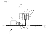
- FIG. 1 shows schematically a coupling, which is provided with the reference numeral 1. Of the coupling 1, only the upper part with respect to a rotation axis 2 is shown.
- the coupling 1 comprises a pressure plate 3 and an abutment plate 4, wherein pressure plate 3 and abutment plate 4 are rotatably connected to each other via a coupling pot 5. In the axial direction, ie. in the direction of the axis of rotation 2, the pressure plate 3 can be moved.
- the abutment plate is rotatably connected to an input shaft 6 of the coupling 1.
- the input shaft 6 may be, for example, the crankshaft of an internal combustion engine, not shown here, of a motor vehicle.
- a clutch disc 7 is arranged with friction linings 8.
- the clutch disc 7 is rotatably connected to an output shaft 9 of the clutch 1.
- the output shaft 9 may represent, for example, the input shaft of a gearbox.
- the clutch actuator 10 is connected via a diaphragm spring 12 to the pressure plate 3. In the position of the clutch actuator 10 shown in FIG. 1, the clutch 1 should be completely closed, ie, the clutch actuator 10 assumes an end position in the direction of the rotational axis 2.
- FIG. 2 shows the flow chart of a preferred embodiment of the invention.
- the method is started when, for example, a motor vehicle with the friction clutch 1 is started (see block 20, "System start”). Thereafter, in step 21 (or block 21), the clutch temperature is determined.
- the clutch temperature is determined.
- a simple possibility is to base the temperature of the intake air from the engine of the motor vehicle, since this is measured anyway. For a longer downtime of the motor vehicle, the clutch temperature corresponds exactly to the ambient temperature or the temperature of the intake air.
- step 22 the determination of the end position of the clutch actuator with fully closed clutch (friction clutch 1).
- a reference value pair can be determined, consisting of the end position of the clutch actuator 10 and the determined reference temperature, which preferably corresponds to the ambient temperature.
- step 23 After a temperature model has been initialized (step 23), which preferably determines the temperature of the friction clutch 1 on the basis of an energy balance even with an opened clutch, the temperature of the friction clutch 1 is calculated in step 24. At regular intervals, which is carried out by a query 25, whether a defined period has expired, the end position of the clutch actuator 10th determined (step 26). Based on a stored characteristic (or a stored characteristic field), which shows the relationship between the temperature of the friction clutch and the end position of the clutch actuator 10 with fully closed friction clutch 1, the temperature is determined in step 27. At this temperature, the temperature model is adjusted in step 28.
- a stored characteristic or a stored characteristic field
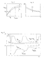
- FIG. 3 shows an example of the characteristic already mentioned above, which shows the relationship between temperature T and end position X. Shown are three different characteristics for different speeds n of the engine of the motor vehicle.
- a reference value T R is entered in FIG. 3, which is to correspond to the determined reference temperature after the system has been started (compare steps 20 and 21 in FIG. Since a reference end position X R (see step 22 in FIG. 2) is also determined immediately after system start 20 when the clutch is fully engaged, the characteristic curves can be shifted such that the determined reference value pair lies on the corresponding characteristic curve. By adjusting long-term changes in the final position of the clutch actuator 10 such as wear, etc. are taken into account. On the basis of the characteristic field adapted in this way, it is now possible to deduce the instantaneous temperature of the friction clutch 1 when the end position is known during operation of the motor vehicle (see X Mess and T Berech in FIG. 3).
- FIG. 4 shows characteristic curves from which the temperature T of the friction clutch 1 can be deduced from a distance ⁇ X of the gripping point of the friction clutch 1 to the end position of the clutch actuator 10. For this, the position of the gripping point must be known, which can be determined by appropriate methods.
- FIG. 5 shows a profile of the position P of the clutch actuator 10 (upper diagram) and a profile of the temperature T of the friction clutch 1 (lower diagram) over time.
- the friction clutch 1 is fully opened and then fully closed, so that it (after completion of system start 20) occupies the final position X R.
- the temperature T R is also determined to be long-term by calibrating the characteristic curves according to FIGS. 3 or 4 Influences on the end position of the clutch actuator such as wear etc. can compensate.
- the temperature of the friction clutch increases due to several opening and closing operations in which the friction clutch transmits torque in some cases with slip while heat is released. Heat emission to the environment also leads to a drop in temperature, for example, when the clutch is fully open.
- the upper temperature curve T Real should correspond to the actual temperature of the friction clutch, while the lower temperature curve T model is to reflect the temperatures that are calculated by the temperature model.
- the end position of the clutch actuator changes when the clutch is fully closed.
- the end position E 31 or E 32 is at a distance from the end position ER.
- a comparison of the temperature model takes place on the basis of the determined or calculated temperature T Berech on the basis of the measured values X Mess . According to the adjustment, the curves T Real and T Model are merged.
Landscapes
- Physics & Mathematics (AREA)
- Engineering & Computer Science (AREA)
- General Engineering & Computer Science (AREA)
- Electromagnetism (AREA)
- Fluid Mechanics (AREA)
- Mechanical Engineering (AREA)
- Hydraulic Clutches, Magnetic Clutches, Fluid Clutches, And Fluid Joints (AREA)
Priority Applications (2)
| Application Number | Priority Date | Filing Date | Title |
|---|---|---|---|
| DE502005006276T DE502005006276D1 (de) | 2005-07-06 | 2005-07-06 | Verfahren zur Bestimmung der Temperatur einer Reibkupplung |
| EP05106132A EP1741949B1 (fr) | 2005-07-06 | 2005-07-06 | Méthode pour déterminer la température d'un embrayage à friction |
Applications Claiming Priority (1)
| Application Number | Priority Date | Filing Date | Title |
|---|---|---|---|
| EP05106132A EP1741949B1 (fr) | 2005-07-06 | 2005-07-06 | Méthode pour déterminer la température d'un embrayage à friction |
Publications (2)
| Publication Number | Publication Date |
|---|---|
| EP1741949A1 true EP1741949A1 (fr) | 2007-01-10 |
| EP1741949B1 EP1741949B1 (fr) | 2008-12-17 |
Family
ID=35057121
Family Applications (1)
| Application Number | Title | Priority Date | Filing Date |
|---|---|---|---|
| EP05106132A Ceased EP1741949B1 (fr) | 2005-07-06 | 2005-07-06 | Méthode pour déterminer la température d'un embrayage à friction |
Country Status (2)
| Country | Link |
|---|---|
| EP (1) | EP1741949B1 (fr) |
| DE (1) | DE502005006276D1 (fr) |
Cited By (1)
| Publication number | Priority date | Publication date | Assignee | Title |
|---|---|---|---|---|
| CN112431876A (zh) * | 2019-08-26 | 2021-03-02 | 上海汽车集团股份有限公司 | 干式离合器的温度估计方法及装置 |
Citations (6)
| Publication number | Priority date | Publication date | Assignee | Title |
|---|---|---|---|---|
| US5067599A (en) * | 1989-07-07 | 1991-11-26 | Fichtel & Sachs Ag | Arrangement for controlling a motor friction clutch |
| US5307269A (en) | 1989-04-12 | 1994-04-26 | Zexel Corporation | Method for correcting clutch control data in accordance with disk temperature |
| FR2828719A1 (fr) * | 2001-08-16 | 2003-02-21 | Luk Lamellen & Kupplungsbau | Procede servant a commander un embrayage et dispositif servant a actionner un embrayage |
| DE10316419A1 (de) * | 2002-04-10 | 2003-11-06 | Luk Lamellen & Kupplungsbau | Verfahren zur Erkennung einer Leckage eines hydraulischen Ausrücksystems einer Doppelkupplung eines Paralleschaltgetriebes |
| EP1416182A2 (fr) | 2002-10-30 | 2004-05-06 | Aisin Seiki Kabushiki Kaisha | Dispositif de commande d'embrayage |
| EP1491787A1 (fr) * | 2003-06-23 | 2004-12-29 | LuK Lamellen und Kupplungsbau Beteiligungs KG | Procédé et dispositif pour contrôler un embrayage |
-
2005
- 2005-07-06 EP EP05106132A patent/EP1741949B1/fr not_active Ceased
- 2005-07-06 DE DE502005006276T patent/DE502005006276D1/de not_active Expired - Lifetime
Patent Citations (6)
| Publication number | Priority date | Publication date | Assignee | Title |
|---|---|---|---|---|
| US5307269A (en) | 1989-04-12 | 1994-04-26 | Zexel Corporation | Method for correcting clutch control data in accordance with disk temperature |
| US5067599A (en) * | 1989-07-07 | 1991-11-26 | Fichtel & Sachs Ag | Arrangement for controlling a motor friction clutch |
| FR2828719A1 (fr) * | 2001-08-16 | 2003-02-21 | Luk Lamellen & Kupplungsbau | Procede servant a commander un embrayage et dispositif servant a actionner un embrayage |
| DE10316419A1 (de) * | 2002-04-10 | 2003-11-06 | Luk Lamellen & Kupplungsbau | Verfahren zur Erkennung einer Leckage eines hydraulischen Ausrücksystems einer Doppelkupplung eines Paralleschaltgetriebes |
| EP1416182A2 (fr) | 2002-10-30 | 2004-05-06 | Aisin Seiki Kabushiki Kaisha | Dispositif de commande d'embrayage |
| EP1491787A1 (fr) * | 2003-06-23 | 2004-12-29 | LuK Lamellen und Kupplungsbau Beteiligungs KG | Procédé et dispositif pour contrôler un embrayage |
Cited By (2)
| Publication number | Priority date | Publication date | Assignee | Title |
|---|---|---|---|---|
| CN112431876A (zh) * | 2019-08-26 | 2021-03-02 | 上海汽车集团股份有限公司 | 干式离合器的温度估计方法及装置 |
| CN112431876B (zh) * | 2019-08-26 | 2022-05-27 | 上海汽车集团股份有限公司 | 干式离合器的温度估计方法及装置 |
Also Published As
| Publication number | Publication date |
|---|---|
| EP1741949B1 (fr) | 2008-12-17 |
| DE502005006276D1 (de) | 2009-01-29 |
Similar Documents
| Publication | Publication Date | Title |
|---|---|---|
| EP2315963B1 (fr) | Procede de compensation de changements de volume d'un fluide hydraulique dans un dispositif d'actionnement hydraulique destine a actionner un embrayage, ainsi que dispositif d'actionnement hydraulique | |
| DE69521866T2 (de) | Automatisierte Kupplungsbetätigung und -Einstellung | |
| DE19540921A1 (de) | System zur Steuerung einer Servokupplung | |
| EP1999392B1 (fr) | Procédé de commande d'un embrayage automatique à frottement | |
| DE102008057656B4 (de) | Kupplungssystem mit einer automatisierten Reibungskupplung | |
| DE102007015679A1 (de) | Verfahren zur Steuerung einer automatisierten Reibungskupplung | |
| DE112013003567B4 (de) | Verfahren zur Ermittlung von Parametern einer Reibungskupplungseinrichtung | |
| DE60007330T2 (de) | Antriebseinheit eines fahrzeugs und verfahren zur feststellung des eingriff-punktes einer automatischen antriebskupplung | |
| DE19837816A1 (de) | Verfahren zum Steuern einer Kupplung | |
| DE102007050301A1 (de) | Verfahren und Vorrichtung zum Erkennen einer Fehlfunktion einer Kupplung | |
| DE102012202413A1 (de) | Verfahren zur Steuerung einer Reibungskupplung | |
| DE10316419B4 (de) | Verfahren zur Erkennung einer Leckage eines hydraulischen Ausrücksystems einer Doppelkupplung eines Parallelschaltgetriebes | |
| DE10244393B4 (de) | Verfahren zur Bestimmung des Eingriffspunkts einer hydraulisch betätigten Kupplung | |
| DE10343096B4 (de) | Verfahren und Vorrichtung zum Vermeiden von durch Axialverschiebungen zwischen einer Kupplungseingangswelle und einer Kupplungsausgangswelle bedingten Referenzpositionsverschiebungen einer von einem Aktor betätigten Kupplung | |
| DE102012103408A1 (de) | Verfahren zur Adaption einer Trennkupplung | |
| EP1775449B1 (fr) | Ligne de transmission pour véhicule et méthode pour l'utilisation d'une telle ligne de transmission | |
| EP1456553B1 (fr) | Procede de determination du point d'application d'un embrayage | |
| EP1741949B1 (fr) | Méthode pour déterminer la température d'un embrayage à friction | |
| DE112019001443T5 (de) | Kupplungssteuervorrichtung | |
| DE102020122295A1 (de) | Verfahren zur Steuerung einer Reibungskupplung und Drehmomentübertragungseinrichtung mit dieser | |
| DE102019215674A1 (de) | Verfahren zur Regelung eines Stellaktuators | |
| DE102019219961A1 (de) | Verfahren zur Auflösung einer Zahn-auf-Zahn-Stellung eines formschlüssigen Schaltelements eines automatisierten Schaltgetriebes und Steuergerät | |
| DE19856541A1 (de) | Verfahren zum Initialisieren eines Kraftfahrzeug-Antriebsstrangs | |
| DE102015200981B4 (de) | Verfahren zum Kontrollieren einer von einer Reibungskupplungseinrichtung übertragenen mechanischen Leistung | |
| WO2017174075A1 (fr) | Procédé de détermination d'une température de système d'une section hydrostatique d'un système d'embrayage hydraulique |
Legal Events
| Date | Code | Title | Description |
|---|---|---|---|
| PUAI | Public reference made under article 153(3) epc to a published international application that has entered the european phase |
Free format text: ORIGINAL CODE: 0009012 |
|
| AK | Designated contracting states |
Kind code of ref document: A1 Designated state(s): AT BE BG CH CY CZ DE DK EE ES FI FR GB GR HU IE IS IT LI LT LU LV MC NL PL PT RO SE SI SK TR |
|
| AX | Request for extension of the european patent |
Extension state: AL BA HR MK YU |
|
| 17P | Request for examination filed |
Effective date: 20070710 |
|
| AKX | Designation fees paid |
Designated state(s): AT BE BG CH CY CZ DE DK EE ES FI FR GB GR HU IE IS IT LI LT LU LV MC NL PL PT RO SE SI SK TR |
|
| 17Q | First examination report despatched |
Effective date: 20070926 |
|
| GRAP | Despatch of communication of intention to grant a patent |
Free format text: ORIGINAL CODE: EPIDOSNIGR1 |
|
| GRAJ | Information related to disapproval of communication of intention to grant by the applicant or resumption of examination proceedings by the epo deleted |
Free format text: ORIGINAL CODE: EPIDOSDIGR1 |
|
| GRAP | Despatch of communication of intention to grant a patent |
Free format text: ORIGINAL CODE: EPIDOSNIGR1 |
|
| GRAS | Grant fee paid |
Free format text: ORIGINAL CODE: EPIDOSNIGR3 |
|
| RBV | Designated contracting states (corrected) |
Designated state(s): DE FR GB |
|
| GRAA | (expected) grant |
Free format text: ORIGINAL CODE: 0009210 |
|
| RIN1 | Information on inventor provided before grant (corrected) |
Inventor name: HINSBERGER, UWE Inventor name: LEIBBRANDT, MARTIN Inventor name: SCHMITZ, HARALD |
|
| RAP1 | Party data changed (applicant data changed or rights of an application transferred) |
Owner name: GETRAG FORD TRANSMISSIONS GMBH |
|
| AK | Designated contracting states |
Kind code of ref document: B1 Designated state(s): DE FR GB |
|
| REG | Reference to a national code |
Ref country code: GB Ref legal event code: FG4D Free format text: NOT ENGLISH |
|
| REF | Corresponds to: |
Ref document number: 502005006276 Country of ref document: DE Date of ref document: 20090129 Kind code of ref document: P |
|
| PLBE | No opposition filed within time limit |
Free format text: ORIGINAL CODE: 0009261 |
|
| STAA | Information on the status of an ep patent application or granted ep patent |
Free format text: STATUS: NO OPPOSITION FILED WITHIN TIME LIMIT |
|
| 26N | No opposition filed |
Effective date: 20090918 |
|
| REG | Reference to a national code |
Ref country code: FR Ref legal event code: PLFP Year of fee payment: 12 |
|
| REG | Reference to a national code |
Ref country code: FR Ref legal event code: PLFP Year of fee payment: 13 |
|
| REG | Reference to a national code |
Ref country code: FR Ref legal event code: PLFP Year of fee payment: 14 |
|
| PGFP | Annual fee paid to national office [announced via postgrant information from national office to epo] |
Ref country code: FR Payment date: 20190621 Year of fee payment: 15 |
|
| PGFP | Annual fee paid to national office [announced via postgrant information from national office to epo] |
Ref country code: GB Payment date: 20190626 Year of fee payment: 15 Ref country code: DE Payment date: 20190617 Year of fee payment: 15 |
|
| REG | Reference to a national code |
Ref country code: DE Ref legal event code: R119 Ref document number: 502005006276 Country of ref document: DE |
|
| GBPC | Gb: european patent ceased through non-payment of renewal fee |
Effective date: 20200706 |
|
| PG25 | Lapsed in a contracting state [announced via postgrant information from national office to epo] |
Ref country code: GB Free format text: LAPSE BECAUSE OF NON-PAYMENT OF DUE FEES Effective date: 20200706 Ref country code: FR Free format text: LAPSE BECAUSE OF NON-PAYMENT OF DUE FEES Effective date: 20200731 |
|
| PG25 | Lapsed in a contracting state [announced via postgrant information from national office to epo] |
Ref country code: DE Free format text: LAPSE BECAUSE OF NON-PAYMENT OF DUE FEES Effective date: 20210202 |