EP1741987A1 - Cuiseur - Google Patents
Cuiseur Download PDFInfo
- Publication number
- EP1741987A1 EP1741987A1 EP05734622A EP05734622A EP1741987A1 EP 1741987 A1 EP1741987 A1 EP 1741987A1 EP 05734622 A EP05734622 A EP 05734622A EP 05734622 A EP05734622 A EP 05734622A EP 1741987 A1 EP1741987 A1 EP 1741987A1
- Authority
- EP
- European Patent Office
- Prior art keywords
- heating chamber
- temperature
- storage part
- interior
- heating
- Prior art date
- Legal status (The legal status is an assumption and is not a legal conclusion. Google has not performed a legal analysis and makes no representation as to the accuracy of the status listed.)
- Withdrawn
Links
Images


Classifications
-
- F—MECHANICAL ENGINEERING; LIGHTING; HEATING; WEAPONS; BLASTING
- F24—HEATING; RANGES; VENTILATING
- F24C—DOMESTIC STOVES OR RANGES ; DETAILS OF DOMESTIC STOVES OR RANGES, OF GENERAL APPLICATION
- F24C1/00—Stoves or ranges in which the fuel or energy supply is not restricted to solid fuel or to a type covered by a single one of the following groups F24C3/00 - F24C9/00; Stoves or ranges in which the type of fuel or energy supply is not specified
- F24C1/14—Radiation heating stoves and ranges, with additional provision for convection heating
-
- F—MECHANICAL ENGINEERING; LIGHTING; HEATING; WEAPONS; BLASTING
- F24—HEATING; RANGES; VENTILATING
- F24C—DOMESTIC STOVES OR RANGES ; DETAILS OF DOMESTIC STOVES OR RANGES, OF GENERAL APPLICATION
- F24C15/00—Details
- F24C15/32—Arrangements of ducts for hot gases, e.g. in or around baking ovens
- F24C15/322—Arrangements of ducts for hot gases, e.g. in or around baking ovens with forced circulation
- F24C15/327—Arrangements of ducts for hot gases, e.g. in or around baking ovens with forced circulation with air moisturising
Definitions
- the present invention relates to a cooking apparatus and, specifically, the invention relates to a cooking apparatus which can be used to ferment dough.
- Fig. 6 shows a microwave oven 100 which is a cooking apparatus disclosed in the patent reference 1.
- the microwave oven 100 includes a heating chamber 101 in the interior thereof and, in the front opening portion of the heating chamber 101, there is disposed a door (not shown) in such a manner that it can be freely opened and shut.
- a heating chamber 101 in the upper and lower portions of the heating chamber 101, there are respectively disposed heaters 102, 102 which function as heating means; and, between these heaters, there is interposed a cooking dish 103.
- the microwave oven 100 includes a control unit (not shown) which controls the magnetron 104, humidity sensor 105, thermistor 106, heater 110 functioning as heating means, and other similar parts.
- a control unit not shown
- the magnetron 104 controls the magnetron 104, humidity sensor 105, thermistor 106, heater 110 functioning as heating means, and other similar parts.
- the control unit controls the heater 110 to adjust the amount of steam to be sprayed into the heating chamber 101, thereby setting the interior of the heating chamber 101 at a desired humidity.
- the control unit controls the heater 110 to adjust the amount of steam to be sprayed into the heating chamber 101, thereby setting the interior of the heating chamber 101 at a desired humidity.
- the invention is made in view of the above-mentioned problem and thus it is an object of the invention to provide a cooking apparatus which can set the interior of the heating chamber at desired humidity and temperature in a short time.
- the present cooking apparatus capable of supplying steam into a heating chamber with an object to be heated stored therein.
- the present cooking apparatus comprises: heating chamber interior heating means for heating the interior of a heating chamber; water supply means for supplying water into the heating chamber; a storage part for storing the water within the heating chamber; storage part heating means for heating the water stored in the storage part; control part for controlling the heating chamber interior heating means, the water supply means and the storage part heating means; heating chamber interior temperature detect means for detecting the temperature of the interior of the heating chamber; and, storage part temperature detect means for detecting the temperature of the storage part heating means or the temperature of the storage part, wherein the control part controls the storage part heating means and the water supply means based on the temperature of the interior of the heating chamber in such a manner that the water in the storage part is prevented from boiling on.
- an object to be heated is stored into the heating chamber, the interior of the heating chamber is heated up to a given temperature using the heating chamber interior heating means, water supplied to the storage part of the interior of the heating chamber by the water supply means is heated, and the thus generated steam is supplied into the heating chamber.
- the control part based on the temperature of the interior of the heating chamber detected by the heating chamber interior temperature detect means, controls the storage part heating means and the water supply means to supply the steam into the heating chamber in such a manner that the water in the storage part is prevented from boiling on.
- the storage part heating means can be controlled using PWM (Pulse Width Modulation). Also, the storage part heating means can also be controlled in such a manner that it is turned on and off, or it can also be inverter controlled.
- a cooking apparatus capable of supplying steam into a heating chamber with an object to be heated stored therein.
- the present cooking apparatus comprises: heating chamber interior heating means for heating the interior of a heating chamber; water supply means for supplying water into the heating chamber; a storage part for storing the water within the heating chamber; storage part heating means for heating the water stored in the storage part; control part for controlling the heating chamber interior heating means, the water supply means and the storage part heating means; heating chamber interior temperature detect means for detecting the temperature of the interior of the heating chamber; and, storage part temperature detect means for detecting the temperature of the storage part heating means or the temperature of the storage part, wherein the control part controls the storage part heating means and the water supply means based on the temperature of the interior of the heating chamber and the temperature of the storage part in such a manner that the water in the storage part is prevented from boiling on.
- an object to be heated is stored into the heating chamber, the interior of the heating chamber is heated up to a given temperature using the heating chamber interior heating means, water supplied to the storage part of the interior of the heating chamber by the water supply means is heated, and the thus generated steam is supplied into the heating chamber.
- the control part based on the temperature of the interior of the heating chamber detected by the heating chamber interior temperature detect means and the temperature of the storage part detected by the storage part temperature detect means, controls the storage part heating means and the water supply means to supply the steam into the heating chamber in such a manner that the water in the storage part is prevented from boiling on.
- the storage part heating means can be controlled using PWM (Pulse Width Modulation). Also, the storage part heating means can also be controlled in such a manner that it is turned on and off, or it can also be inverter controlled.
- the present cooking apparatus is characterized in that the control part not only controls the water supply means and storage part heating means in such a manner that, after the water in the storage part is boiled once, the water is prevented from boiling on, but also, based on the temperature detected by the heating chamber interior detect means, controls the temperature of the interior of the heating chamber at a desired temperature using the heating chamber interior heating means.
- control part controls the water supply means and storage part heating means in such a manner that, after the water in the storage part is boiled once, the water is prevented from boiling on, not only an increase in the temperature of the steam can be prevented but also an increase in the temperature of the interior of the heating chamber due to supply of the steam can be prevented. Also, because the control part controls the heating chamber interior heating means based on the temperature detected by the heating chamber interior temperature detect means, the temperature of the interior of the heating chamber can be controlled to a desired temperature.
- the present cooking apparatus is characterized in that there are set two or more control levels for controlling the temperature of the storage part based on the temperature detected by the storage part temperature detect means: that is, firstly, the storage part temperature is controlled at a first level, and, from then on, the storage part temperature is controlled at a second level.
- control levels for controlling the storage part heating means that is, in the first control level, the storage part heating means is controlled at a high level to heat the water in the storage part quickly and, from then on, it is controlled at the second level which is lower than the first level, thereby supplying a given amount of steam.
- the present cooking apparatus is characterized in that there are set two or more control levels for controlling the temperature of the interior of the heating chamber based on the temperature detected by the heating chamber interior temperature detect means, and the storage part heating means is controlled at the highest level of the thus set heating chamber interior temperature control levels.
- control levels for controlling the heating chamber interior temperature according to the temperature detected by the heating chamber interior temperature detect means, and the storage part heating means is controlled at the highest level of the thus set control levels, whereby the amount of supply of steam is maximized while minimizing an increase in the temperature of the interior of the heating chamber.
- the present cooking apparatus is characterized in that the control part controls the storage part heating means in such a manner that, when the temperature of the storage part exceeds the temperature of the interior of the heating chamber, the water in the storage part is prevented from boiling.
- the storage part heating means is controlled so as to prevent the water in the storage part from boiling, generation of an excessive amount of steam can be prevented and thus the humidity of the interior of the heating chamber can be maintained at a proper level.
- the present cooking apparatus is characterized by ventilating means for feeding the air into the heating chamber.
- the ventilating means is controlled in such a manner that the temperature of the interior of the heating chamber can be set a temperature proper for fermentation based on the temperature detected by the heating temperature interior temperature detect means.
- control part controls the ventilating means based on the temperature detected by the heating chamber interior temperature detect means to thereby set the interior of the heating chamber at a proper temperature for fermentation.
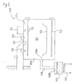
- Fig. 1 is a front view of an ordinary microwave oven having a steam function which is an embodiment of a cooking apparatus according to the invention
- Fig. 2 is a side view of the microwave oven shown in Fig. 1
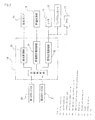
- Fig. 3 is a block diagram of the structure of a control part and a control system
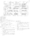
- Fig. 4 is a graphical representation of the control contents to be executed by the control part
- Fig. 5 is a comparison table for showing fermentation states provided according to steam fermentation control by heating sources.
- This microwave oven 10 is a cooking apparatus which can supply steam into a heating chamber 12 with an object to be heated 11 stored therein.
- the cooking apparatus 10 comprises: a heater 13 serving as heating chamber interior heating means for heating the interior of the heating chamber 12; a tank 15 and a water pump 16 serving as water supply means for supplying water 14 into the heating chamber 12; an evaporation dish 17 serving as a storage part for storing the water 14 within the heating chamber 12; a storage part heating part 18 serving as storage part heating means for heating the water 14 in the evaporation dish 17; a control part 19 for controlling the heater 13, water pump 16 and storage part heating part 18; and, a heating chamber interior thermistor 20 serving as heating chamber interior temperature detect means for detecting the temperature of the interior of the heating chamber 12. Also, on the outer surface of the evaporation dish 17 serving as the storage part, there is provided a storage part thermistor 21 serving as storage part temperature detect means for detecting the temperature of the evaporation dish 17.
- the storage part temperature detect means may measure the temperature of the water directly, or it may be disposed in the vicinity of the evaporation dish to measure the temperature of steam.
- the microwave oven 10 includes a main body 22 having, for example, a rectangular shape and also includes a heating chamber 12 in the inside thereof.
- a door (not shown) in such a manner that it can be freely opened and shut, thereby being able to close the heating chamber 12 hermetically.
- an infrared sensor 27 On the upper wall 12a of the heating surface 12, there is provided an infrared sensor 27, thereby being able to measure the initial temperature of the interior of the heating chamber 12. By the way, this infrared sensor 27 is not be able to measure accurately the temperature of the interior of the heating chamber 12 after the interior of the heating chamber 12 is filled with steam.
- a heating chamber interior thermistor 20 serving as heating chamber interior temperature detect means for detecting the temperature of the interior of the heating chamber 12; and, the thermistor 20 always detects the temperature of the interior of the heating chamber 12 and feeds the detected temperature back to the control part 19.
- the heaters 13 serving as heating chamber interior heating means are disposed respectively in the upper and lower portions of the heating chamber 12 and, between the upper and lower heaters 13, there are interposed a shelf 23 and a cooking dish 24 on which an object to be heated such as a food or dough can be placed. Also, on the back wall 12c of the heating chamber 12, there is provided a convection heater 24 and, in the rear of the convection heater 24, there is provided a fan 26 serving as ventilating means.
- the heating chamber 12 is structured such that, using not only the upper and lower heaters 13 and 13 but also the convection heater 25 and fan 26, a hot wind is forcibly convected to thereby heat the object to be heated 11. Also, the fan 26 can also be used to diffuse steam supplied to the heating chamber 12.
- the evaporation dish 17, which is the storage part for storing the water 14 in the interior of the heating chamber 12, is disposed in the lower portion of the heating chamber 12.
- This evaporation dish 17 is used to store a small amount of, for example, about 20cc of, water 14 and is structured such that the water 14 can be evaporated in a short time by the storage part heating part 18 disposed downwardly of the evaporation dish 17.
- the storage part heating part 18 is disposed in contact with the lower surface of the evaporation dish 17 and is also arranged to heat the evaporation dish 17 uniformly but not suddenly through the main body 22 made of aluminum die cast heated by a heating member such as a Nichrome wire to thereby prevent the water 14 from boiling locally.
- the tank 15 and water pump 16 In a chamber 28 formed adjacent to the side surface of the heating chamber 12, there are stored the tank 15 and water pump 16; and, the water 14 stored in the tank 15 can be supplied through a pipe 16a by the water pump 16 to the evaporation dish 17 placed within the heating chamber 12. Therefore, the water 14 to be supplied to the evaporation dish 17 is water before heated, and thus the temperature of the water 14 is normally lower than the temperature of the interior of the heating chamber 12.
- the control part 19 includes: a compare and judge portion 29 for receiving detect signals from the heating chamber interior thermistor 20 and storage part thermistor 21 to compare the detected temperatures with the reference temperature; a water control portion 30 for controlling the water pump 16; a storage part heating control portion 31 for controlling the storage part heating part 18; a heating chamber interior heating control portion 32 for controlling the heaters 13 or the like serving as the heating chamber interior heating means; and, other similar portions.
- a magnetron 33 By the way, on the upper wall 12a of the heating chamber 12, there is provided a magnetron 33, whereby the heating chamber 12 can be heated by microwaves.
- the fermentation time (the approximate time necessary for the dough to rise 2.5 to 3 times in size) varies greatly depending on the time taken for kneading the bread dough and, therefore, for example, when a temperature in the kneading operation is 27°C, it is necessary to keep the temperature of the interior of the heating chamber at the optimum temperature for fermentation, that is, a temperature in the vicinity of 30°C.
- the point of the bread bakery is to ferment the bread dough properly using yeasts, and the relationship between the fermentation temperature and time is the most important.
- the bread dough rises too much.
- the baked bread has no appetizing color but is rough in the skin and is heavy; and, in some cases, the bread can smell bad.
- the fermentation temperature is excessively high, the bread dough, as in the over-fermented case, rises too much.
- the baked bread has no baked color but is heavy and rough; and, in some cases, the bread can smell bad.
- the fermentation temperature is out of a temperature zone where the yeasts can increase most actively.
- the fermentation temperature is equal to or higher than 60°C, some of the yeasts can die.
- the humidity of the heating chamber preferably, the humidity may be 80% or so; and, what is important is that the surface of the bread dough can be prevented from drying. When the dough surface dries, the increase of the dough is poor and the skin of the dough is thick, resulting in the poor bread.
- control level of the storage part heating part 18 is set for two or more levels (here, for example, 2 levels are set: that is, one level is a first or high level for boiling; and, the other is a second or low level for fermentation).
- 2 levels are set: that is, one level is a first or high level for boiling; and, the other is a second or low level for fermentation.
- a heater for steam serving as the storage part heating part 18 is controlled at the first high level (storage part thermistor level (a)) for boiling to thereby quickly filling steam into the heating chamber 12.
- the storage part heating part 18 is on and off controlled at the storage part thermistor level (b) lower than the first-time storage part thermistor level (a) so as to be able to maintain the humidity suitable for fermentation (for example, 80% - 85%) .
- the storage part thermistor level (b) is a level which is applied to the second time and following times for filling the steam into the interior of the heating chamber to thereby maintain the proper humidity thereof.
- the convection heater 25 serving as the heating chamber interior heating means is turned on to increase the temperature of the interior of the heating chamber, for example, up to the temperature range of 30°C - 35°C suitable for fermentation.
- a circulation fan 26 may be operated strongly or softly or turned off to thereby set uniform the temperature and humidity of the interior of the heading chamber.
- the upper and lower heaters 13 as well as the convection heater 25 are turned off; and, in order that the temperature of the interior of the heating chamber can be maintained in the range suitable for fermentation, the storage part heating part 18 may be on/off controlled at the storage part thermistor level (b), and/or the intensity of the fan 26 may be controlled.
- the convection heater 25 is turned on to increase the temperature of the interior of the heating chamber.
- the storage part heating part 18 is controlled at the storage part thermistor level (b) so as not to boil the water, the temperature of the interior of the heating chamber gradually increases; and, therefore, the storage part heating part 18 and fan 26 are controlled at a storage part thermistor level (d). Thanks to this control, while maintaining the humidity of the interior of the heating chamber at the humidity suitable for fermentation, the temperature thereof can also be maintained at the temperature suitable for fermentation.
- FIG. 5 shows fermentation states provided according to steam fermentation control methods by heating sources.
- the humidity is short and thus the state of the interior of the heating chamber is not desirable. Also, it is difficult to maintain the temperature of the interior of the heating chamber and thus the state of the temperature thereof is not so desirable. Therefore, it is difficult to maintain constant the proper humidity and temperature of the interior of the heating chamber and thus, as a general evaluation, this fermentation control method is not so desirable.
- this fermentation method is a general method when using a cooking apparatus, and the humidity of the interior of the heating chamber is controlled by a user spraying steam into the interior of the heating chamber. As a general evaluation, this fermentation method is not so desirable.
- the microwave oven 100 which is a cooking apparatus, not only because the temperature of the interior of the heating chamber 12 can be increased quickly up to a desired temperature but also because, by supplying the steam with the water not boiling, the steam can be supplied without increasing the temperature of the interior of the heating chamber 12, while preventing the excessive progress of the fermentation, the fermentation can be carried out properly. Also, since the temperature of the steam is equal to or higher than the temperature of the interior of the heating chamber, by controlling the amount of the steam, the temperature of the interior of the heating chamber 12 can be maintained at a given temperature.
- a cooking apparatus according to the invention is not limited to the above-mentioned embodiment but proper changes and modifications are also possible.
- the temperature of the interior of the heating chamber can be increased up to a desired temperature but also since, by supplying steam with water not boiling, the steam can be supplied into the heating chamber without increasing the temperature of the interior of the heating chamber, the excessive progress of the fermentation can be prevented and thus the fermentation can be carried out properly.
Landscapes
- Engineering & Computer Science (AREA)
- Chemical & Material Sciences (AREA)
- Combustion & Propulsion (AREA)
- Mechanical Engineering (AREA)
- General Engineering & Computer Science (AREA)
- Electric Ovens (AREA)
- Cookers (AREA)
Applications Claiming Priority (2)
| Application Number | Priority Date | Filing Date | Title |
|---|---|---|---|
| JP2004130930A JP4739688B2 (ja) | 2004-04-27 | 2004-04-27 | 加熱調理器 |
| PCT/JP2005/007521 WO2005106332A1 (fr) | 2004-04-27 | 2005-04-20 | Cuiseur |
Publications (2)
| Publication Number | Publication Date |
|---|---|
| EP1741987A1 true EP1741987A1 (fr) | 2007-01-10 |
| EP1741987A4 EP1741987A4 (fr) | 2008-06-11 |
Family
ID=35241757
Family Applications (1)
| Application Number | Title | Priority Date | Filing Date |
|---|---|---|---|
| EP05734622A Withdrawn EP1741987A4 (fr) | 2004-04-27 | 2005-04-20 | Cuiseur |
Country Status (5)
| Country | Link |
|---|---|
| US (1) | US20070215142A1 (fr) |
| EP (1) | EP1741987A4 (fr) |
| JP (1) | JP4739688B2 (fr) |
| CN (1) | CN1950644A (fr) |
| WO (1) | WO2005106332A1 (fr) |
Cited By (1)
| Publication number | Priority date | Publication date | Assignee | Title |
|---|---|---|---|---|
| EP1741987A4 (fr) * | 2004-04-27 | 2008-06-11 | Matsushita Electric Industrial Co Ltd | Cuiseur |
Families Citing this family (22)
| Publication number | Priority date | Publication date | Assignee | Title |
|---|---|---|---|---|
| JP4976937B2 (ja) * | 2007-07-03 | 2012-07-18 | 株式会社東芝 | 加熱調理器 |
| JP4987570B2 (ja) * | 2007-05-28 | 2012-07-25 | 株式会社東芝 | 加熱調理器 |
| JP5130363B2 (ja) * | 2008-06-13 | 2013-01-30 | 株式会社 T.M.L | 加熱調理装置 |
| KR20100046735A (ko) * | 2008-10-28 | 2010-05-07 | 엘지전자 주식회사 | 조리기기 및 그 제어방법 |
| JP2010210120A (ja) * | 2009-03-09 | 2010-09-24 | Toshiba Corp | 加熱調理器 |
| EP2390587B1 (fr) * | 2010-05-27 | 2019-07-17 | BSH Hausgeräte GmbH | Appareil de cuisson doté d'une fonction de production de vapeur |
| AU2011334962B2 (en) * | 2010-12-02 | 2015-10-29 | Société des Produits Nestlé S.A. | Low-inertia thermal sensor in a beverage machine |
| CN102135282B (zh) * | 2011-04-27 | 2012-06-20 | 徐州佳乐节能科技有限公司 | 多用节能电磁炉 |
| CH704191A2 (de) * | 2012-04-18 | 2012-05-31 | V Zug Ag | Gargerät und Verfahren zum Garen von Gargut. |
| CN102705879B (zh) * | 2012-05-09 | 2015-04-22 | 广东美的厨房电器制造有限公司 | 蒸汽微波炉及其烹饪方法 |
| JP6229161B2 (ja) * | 2014-02-24 | 2017-11-15 | パナソニックIpマネジメント株式会社 | マイクロ波加熱調理器 |
| US11266274B2 (en) * | 2014-06-26 | 2022-03-08 | Fishsix Rc | Catering box with active climate control for transporting delicate food items |
| CA2973550C (fr) | 2015-01-23 | 2023-09-26 | Balmuda Inc. | Dispositif de chauffage et de cuisson |
| US10973360B2 (en) | 2015-03-25 | 2021-04-13 | Illinois Tool Works Inc. | Steam generator |
| US10357126B2 (en) * | 2015-03-25 | 2019-07-23 | Illinois Tool Works Inc. | Steam generator |
| JP6528125B2 (ja) * | 2015-06-12 | 2019-06-12 | パナソニックIpマネジメント株式会社 | 加熱調理器 |
| EP3108774B1 (fr) * | 2015-06-24 | 2021-01-13 | Electrolux Appliances Aktiebolag | Recipient de cuisson pour la cavite d'un four de cuisson |
| CN109477639B (zh) * | 2016-08-10 | 2020-06-23 | 夏普株式会社 | 加热调理器 |
| CN108344002A (zh) * | 2018-01-22 | 2018-07-31 | 中国地质大学(武汉) | 一种便携式的指定温度加热红外测温微波炉 |
| CN110664228B (zh) * | 2019-11-16 | 2021-08-24 | 广东天际电器股份有限公司 | 一种低温烹饪方法 |
| KR20220004356A (ko) * | 2020-07-03 | 2022-01-11 | 엘지전자 주식회사 | 조리기기 제어방법 |
| CN112586531B (zh) * | 2020-12-14 | 2022-04-15 | 广东美的厨房电器制造有限公司 | 烹饪器具的控制方法、烹饪器具和可读存储介质 |
Family Cites Families (21)
| Publication number | Priority date | Publication date | Assignee | Title |
|---|---|---|---|---|
| JPS5482088U (fr) * | 1977-11-22 | 1979-06-11 | ||
| US4173215A (en) * | 1977-12-05 | 1979-11-06 | Mscan Metal Canada Limitee | Apparatus for steaming foods |
| JPS6029838Y2 (ja) * | 1978-01-18 | 1985-09-07 | 株式会社東芝 | 蒸し器付オ−ブン |
| JPS54179579U (fr) * | 1978-06-08 | 1979-12-19 | ||
| JPS5832081Y2 (ja) * | 1978-09-07 | 1983-07-16 | 株式会社東芝 | 高周波加熱装置 |
| JPS5642020A (en) * | 1979-09-11 | 1981-04-20 | Hitachi Heating Appliance Co Ltd | Steam heating cooker |
| JPS591930A (ja) * | 1982-06-28 | 1984-01-07 | Sanyo Electric Co Ltd | 調理器 |
| US4770888A (en) * | 1986-01-13 | 1988-09-13 | Properties Leasing Company Inc. | Cooking treatment process |
| JPS63105327A (ja) * | 1986-10-23 | 1988-05-10 | Hitachi Heating Appliance Co Ltd | 調理器用加熱制御装置 |
| JPS63114235U (fr) * | 1987-01-19 | 1988-07-22 | ||
| JP3272168B2 (ja) * | 1994-10-14 | 2002-04-08 | 三菱電機株式会社 | 加湿器 |
| US5558010A (en) * | 1995-01-13 | 1996-09-24 | Properties Leasing | Food storage chamber door open compensation |
| JPH094848A (ja) * | 1995-06-22 | 1997-01-10 | Matsushita Electric Ind Co Ltd | 複合型調理器 |
| CA2289592A1 (fr) * | 1997-05-17 | 1998-11-26 | Wolfgang Hofer | Dispositif et procede de cuisson au four |
| US6035763A (en) * | 1998-04-16 | 2000-03-14 | Yung; Simon K. C. | Breadmaker with improved temperature and humidity control |
| JP2003050015A (ja) * | 2001-08-06 | 2003-02-21 | Sharp Corp | 加熱調理装置 |
| JP3775352B2 (ja) * | 2002-06-14 | 2006-05-17 | 松下電器産業株式会社 | 高周波加熱装置 |
| JP3867637B2 (ja) * | 2002-07-30 | 2007-01-10 | 松下電器産業株式会社 | 蒸気発生装置及び蒸気発生装置を備えた加熱調理装置 |
| JP2005069550A (ja) * | 2003-08-22 | 2005-03-17 | Tml:Kk | 低温度で飽和蒸気を発生させる方法およびその装置 |
| JP4739688B2 (ja) * | 2004-04-27 | 2011-08-03 | パナソニック株式会社 | 加熱調理器 |
| KR100598388B1 (ko) * | 2004-08-19 | 2006-07-07 | 삼성전자주식회사 | 과열증기조리기 |
-
2004
- 2004-04-27 JP JP2004130930A patent/JP4739688B2/ja not_active Expired - Fee Related
-
2005
- 2005-04-20 CN CNA2005800135578A patent/CN1950644A/zh active Pending
- 2005-04-20 US US10/599,781 patent/US20070215142A1/en not_active Abandoned
- 2005-04-20 EP EP05734622A patent/EP1741987A4/fr not_active Withdrawn
- 2005-04-20 WO PCT/JP2005/007521 patent/WO2005106332A1/fr not_active Ceased
Cited By (1)
| Publication number | Priority date | Publication date | Assignee | Title |
|---|---|---|---|---|
| EP1741987A4 (fr) * | 2004-04-27 | 2008-06-11 | Matsushita Electric Industrial Co Ltd | Cuiseur |
Also Published As
| Publication number | Publication date |
|---|---|
| US20070215142A1 (en) | 2007-09-20 |
| WO2005106332A1 (fr) | 2005-11-10 |
| CN1950644A (zh) | 2007-04-18 |
| JP4739688B2 (ja) | 2011-08-03 |
| EP1741987A4 (fr) | 2008-06-11 |
| JP2005315449A (ja) | 2005-11-10 |
Similar Documents
| Publication | Publication Date | Title |
|---|---|---|
| EP1741987A1 (fr) | Cuiseur | |
| EP2754355B1 (fr) | Procédé de cuisson à la vapeur et four de cuisson à la vapeur | |
| EP1767860B1 (fr) | Procédé de fonctionnement d'un four avec système de chauffage, système micro-ondes et système à vapeur | |
| US8455028B2 (en) | Method for conducting at least one cooking process | |
| US20070272676A1 (en) | Cooker | |
| JP2005226872A (ja) | 加熱調理器及び加熱調理方法 | |
| US7745763B2 (en) | Method for baking bread using steam | |
| CN101377317B (zh) | 加热烹调器 | |
| CN114060870A (zh) | 烹饪器具的控制方法、烹饪器具和计算机可读存储介质 | |
| EP2728966A1 (fr) | Appareil de cuisson à haute fréquence | |
| WO1981002058A1 (fr) | Cuiseur thermique | |
| CN108158393B (zh) | 煮饭器和使用该煮饭器进行保温的方法 | |
| JP5241566B2 (ja) | 加熱調理器 | |
| CN113040596B (zh) | 一种集成灶的控制方法及装置 | |
| JP2012102917A (ja) | 蒸気調理器 | |
| CN114222390A (zh) | 烹饪器具、烹饪器具的控制方法和装置、可读存储介质 | |
| JP4901936B2 (ja) | 加熱調理器 | |
| JPH0486418A (ja) | 加熱調理装置 | |
| CN110859487A (zh) | 真空烹饪器具及其烹饪方法 | |
| JP3864990B2 (ja) | 複合型調理器 | |
| CN114468753B (zh) | 烹饪器具的无水焗烹饪方法、烹饪器具 | |
| JP3867714B2 (ja) | 複合型調理器 | |
| JP2010210120A (ja) | 加熱調理器 | |
| CN121619688A (zh) | 微波烹饪器具及其控制方法、可读存储介质 | |
| WO2025185447A1 (fr) | Appareil de cuisson et procédé et appareil de commande associés, et dispositif électronique et support de stockage lisible |
Legal Events
| Date | Code | Title | Description |
|---|---|---|---|
| PUAI | Public reference made under article 153(3) epc to a published international application that has entered the european phase |
Free format text: ORIGINAL CODE: 0009012 |
|
| 17P | Request for examination filed |
Effective date: 20061024 |
|
| AK | Designated contracting states |
Kind code of ref document: A1 Designated state(s): DE FR GB |
|
| DAX | Request for extension of the european patent (deleted) | ||
| RBV | Designated contracting states (corrected) |
Designated state(s): DE FR GB |
|
| A4 | Supplementary search report drawn up and despatched |
Effective date: 20080513 |
|
| RAP1 | Party data changed (applicant data changed or rights of an application transferred) |
Owner name: PANASONIC CORPORATION |
|
| 17Q | First examination report despatched |
Effective date: 20081107 |
|
| STAA | Information on the status of an ep patent application or granted ep patent |
Free format text: STATUS: THE APPLICATION IS DEEMED TO BE WITHDRAWN |
|
| 18D | Application deemed to be withdrawn |
Effective date: 20090528 |