EP1741996A2 - Collecteur solaire et système de chauffage solaire utilisant un tel collecteur - Google Patents
Collecteur solaire et système de chauffage solaire utilisant un tel collecteur Download PDFInfo
- Publication number
- EP1741996A2 EP1741996A2 EP05028255A EP05028255A EP1741996A2 EP 1741996 A2 EP1741996 A2 EP 1741996A2 EP 05028255 A EP05028255 A EP 05028255A EP 05028255 A EP05028255 A EP 05028255A EP 1741996 A2 EP1741996 A2 EP 1741996A2
- Authority
- EP
- European Patent Office
- Prior art keywords
- cover plate
- solar
- heating
- liquid
- plate
- Prior art date
- Legal status (The legal status is an assumption and is not a legal conclusion. Google has not performed a legal analysis and makes no representation as to the accuracy of the status listed.)
- Withdrawn
Links
Images


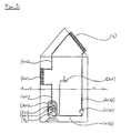
Classifications
-
- E—FIXED CONSTRUCTIONS
- E04—BUILDING
- E04B—GENERAL BUILDING CONSTRUCTIONS; WALLS, e.g. PARTITIONS; ROOFS; FLOORS; CEILINGS; INSULATION OR OTHER PROTECTION OF BUILDINGS
- E04B5/00—Floors; Floor construction with regard to insulation; Connections specially adapted therefor
- E04B5/48—Special adaptations of floors for incorporating ducts, e.g. for heating or ventilating
-
- E—FIXED CONSTRUCTIONS
- E04—BUILDING
- E04F—FINISHING WORK ON BUILDINGS, e.g. STAIRS, FLOORS
- E04F13/00—Coverings or linings, e.g. for walls or ceilings
- E04F13/07—Coverings or linings, e.g. for walls or ceilings composed of covering or lining elements; Sub-structures therefor; Fastening means therefor
- E04F13/08—Coverings or linings, e.g. for walls or ceilings composed of covering or lining elements; Sub-structures therefor; Fastening means therefor composed of a plurality of similar covering or lining elements
- E04F13/0869—Coverings or linings, e.g. for walls or ceilings composed of covering or lining elements; Sub-structures therefor; Fastening means therefor composed of a plurality of similar covering or lining elements having conduits for fluids
-
- E—FIXED CONSTRUCTIONS
- E04—BUILDING
- E04F—FINISHING WORK ON BUILDINGS, e.g. STAIRS, FLOORS
- E04F15/00—Flooring
- E04F15/02—Flooring or floor layers composed of a number of similar elements
-
- E—FIXED CONSTRUCTIONS
- E04—BUILDING
- E04F—FINISHING WORK ON BUILDINGS, e.g. STAIRS, FLOORS
- E04F15/00—Flooring
- E04F15/02—Flooring or floor layers composed of a number of similar elements
- E04F15/02172—Floor elements with an anti-skid main surface, other than with grooves
-
- E—FIXED CONSTRUCTIONS
- E04—BUILDING
- E04F—FINISHING WORK ON BUILDINGS, e.g. STAIRS, FLOORS
- E04F15/00—Flooring
- E04F15/02—Flooring or floor layers composed of a number of similar elements
- E04F15/10—Flooring or floor layers composed of a number of similar elements of other materials, e.g. fibrous or chipped materials, organic plastics, magnesite tiles, hardboard, or with a top layer of other materials
-
- F—MECHANICAL ENGINEERING; LIGHTING; HEATING; WEAPONS; BLASTING
- F24—HEATING; RANGES; VENTILATING
- F24D—DOMESTIC- OR SPACE-HEATING SYSTEMS, e.g. CENTRAL HEATING SYSTEMS; DOMESTIC HOT-WATER SUPPLY SYSTEMS; ELEMENTS OR COMPONENTS THEREFOR
- F24D3/00—Hot-water central heating systems
- F24D3/12—Tube and panel arrangements for ceiling, wall, or underfloor heating
- F24D3/16—Tube and panel arrangements for ceiling, wall, or underfloor heating mounted on, or adjacent to, a ceiling, wall or floor
-
- F—MECHANICAL ENGINEERING; LIGHTING; HEATING; WEAPONS; BLASTING
- F24—HEATING; RANGES; VENTILATING
- F24S—SOLAR HEAT COLLECTORS; SOLAR HEAT SYSTEMS
- F24S10/00—Solar heat collectors using working fluids
- F24S10/50—Solar heat collectors using working fluids the working fluids being conveyed between plates
-
- E—FIXED CONSTRUCTIONS
- E04—BUILDING
- E04F—FINISHING WORK ON BUILDINGS, e.g. STAIRS, FLOORS
- E04F2290/00—Specially adapted covering, lining or flooring elements not otherwise provided for
- E04F2290/02—Specially adapted covering, lining or flooring elements not otherwise provided for for accommodating service installations or utility lines, e.g. heating conduits, electrical lines, lighting devices or service outlets
- E04F2290/023—Specially adapted covering, lining or flooring elements not otherwise provided for for accommodating service installations or utility lines, e.g. heating conduits, electrical lines, lighting devices or service outlets for heating
-
- Y—GENERAL TAGGING OF NEW TECHNOLOGICAL DEVELOPMENTS; GENERAL TAGGING OF CROSS-SECTIONAL TECHNOLOGIES SPANNING OVER SEVERAL SECTIONS OF THE IPC; TECHNICAL SUBJECTS COVERED BY FORMER USPC CROSS-REFERENCE ART COLLECTIONS [XRACs] AND DIGESTS
- Y02—TECHNOLOGIES OR APPLICATIONS FOR MITIGATION OR ADAPTATION AGAINST CLIMATE CHANGE
- Y02B—CLIMATE CHANGE MITIGATION TECHNOLOGIES RELATED TO BUILDINGS, e.g. HOUSING, HOUSE APPLIANCES OR RELATED END-USER APPLICATIONS
- Y02B30/00—Energy efficient heating, ventilation or air conditioning [HVAC]
-
- Y—GENERAL TAGGING OF NEW TECHNOLOGICAL DEVELOPMENTS; GENERAL TAGGING OF CROSS-SECTIONAL TECHNOLOGIES SPANNING OVER SEVERAL SECTIONS OF THE IPC; TECHNICAL SUBJECTS COVERED BY FORMER USPC CROSS-REFERENCE ART COLLECTIONS [XRACs] AND DIGESTS
- Y02—TECHNOLOGIES OR APPLICATIONS FOR MITIGATION OR ADAPTATION AGAINST CLIMATE CHANGE
- Y02E—REDUCTION OF GREENHOUSE GAS [GHG] EMISSIONS, RELATED TO ENERGY GENERATION, TRANSMISSION OR DISTRIBUTION
- Y02E10/00—Energy generation through renewable energy sources
- Y02E10/40—Solar thermal energy, e.g. solar towers
- Y02E10/44—Heat exchange systems
Definitions
- the invention relates to a solar collector with a sun facing, front side arranged, translucent component, an underlying opaque heating plate and a back provided base plate.
- the invention also relates to a solar thermal system incorporating at least one of the solar collectors proposed here.
- the solar thermal system further comprises at least one heat radiating element and / or a hot water tap.
- water-cooled solar collectors and hot-water hot-jet elements can have a comparable design.
- water-flow heat exchanger with incorporated flow channels are known.
- the US-A-5,267,611 a heat exchanger having a porous layer as a central element, which is located on the one hand adjacent to the outwardly final heating surface and on the other hand, a liquid supply layer adjacent.
- the liquid supply layer is crossed by continuous channels crossing at right angles, which are separated from each other by rectangular "island" regions.
- a sealing layer is provided around the porous central layer and around the liquid supply layer with these connecting pipes through which the latter enables the liquid exchange.
- the SU11 65 868-A the proposal for a heat exchanger can be seen, which is equipped in its interior with packets of porous plates, between which non-porous liners are provided for the formation of channels.
- the heat exchanger is flowed through by a heating fluid, which gives off its heat when passing through the porous plates to the heat exchanger.
- a quarry-shaped hot and cooling unit which is preferably made in one piece from a ceramic foam, in the zigzag-shaped channel pattern is incorporated.
- the channels are provided to the outside with fittings through which a liquid is supplied to the unit and can be deducted from the unit.
- the walls of the known hot and cooling unit should have a higher thermal conductivity than the ceramic foam inside the hot and cooling unit.
- the task also relates to a solar thermal system for which the same problem of rust sludge is to be solved as well.
- d 1 is the internal width of the flow channels inside the solar collector; the oxygen- tightness formula O d, 1 ultimately gives an upper limit for the maximum permissible oxygen permeability in grams (oxygen).
- the determination of the oxygen tightness O d, 1 takes place in the sense of the present document in accordance with the specifications of DIN 4726 in the version from January 2000, wherein the valid for plastic pipes DIN specifications are to be transferred to the solar collector according to the invention mutatis mutandis.
- the dimensioning of the oxygen-tightness O d, 1 is carried out on a limited by the opaque heating plate, the base plate and the peripheral upstand body having adjacent to the heating plate for forming the solar collector according to the invention still a light transmissive component.
- the oxygen density O d, 1 of the solar collector according to the invention based on the volume ( V 1 ), in one preferred embodiment satisfies the following formula: O d . 1 ⁇ 0 . 085 G / m 3 ⁇ d 1
- a glass pane is preferably provided in a known manner; very particularly preferably, two glass panes mounted in a layered manner can also be used.
- the at least one glass sheet initially serves to couple in the form of light solar rays in the solar collector. The light then impinges on the surface of the opaque heating plate where it is absorbed by the preferably blackened heating plate surface and converted to longer wavelength thermal radiation.
- the at least one glass pane then further serves to prevent cooling of the Auffilplattenober Assembly to the ambient air. This is done inter alia by a reflection of the radiation radiated from the heating plate back to the heating plate. It is preferred to provide the at least one glass pane with an internal prism in order to optimize the reflection of the heat radiation at the at least one glass pane back to the heating plate.
- d 101 is the internal width of the flow channels in the interior of the liquid-filled room temperature control means; the oxygen- tightness formula O d, 101 ultimately gives an upper limit for the maximum permissible oxygen permeability in grams (oxygen).
- the determination of the oxygen tightness O d, 101 is done in the sense of the present document according to the specifications of DIN 4726 in the version from January 2000, wherein the valid for plastic pipes DIN specifications are to be transferred to the means for tempering rooms according to the invention mutatis mutandis.
- the dimensioning of the oxygen-tightness O d, 101 is carried out on a limited by the first and second cover plate with circumferential upstand body, the water supplied through the common feed line and can be removed again by the common discharge.
- the measurement of the Oxygen permeability at an average temperature of 40 ° C ⁇ 2 K.
- the temperature difference between common supply and common discharge must not exceed 4 K. There are 3 individual measurements to perform. The maximum and minimum values should not differ by more than 0.02 g / (m 3 ⁇ d ).
- the determined average value, to which the formula according to claim 2 and 4 or according to claim 7, second point refers, is rounded to 2 decimal places.
- the oxygen-tightness O d, 101 relating to the volume ( V 101 ) of the room temperature control means according to the invention in a preferred embodiment satisfies the following formula: O d . 101 ⁇ 0 . 085 G / m 3 ⁇ d 101
- the solar thermal system according to the invention provides at least one solar collector, as has already been described above.
- the solar thermal system according to the second variant proposed here at least one removal point of service water ( F 3 ), which is heated by the heat radiation absorbed by the solar collector.
- the solar heat system in addition to the solar collector and the at least one extraction point of service water also includes a heat exchanging component in which the service water ( F 3 ) by means of the liquid ( F 1 ), which can be passed through the solar collector, is heated.
- the previously proposed first and the second variant of the solar thermal system according to the invention are summarized, so that such a system at least one solar collector, as already described above, at least one heat radiating element formed as a liquid-flooded means for tempering rooms, as it has already been described above, at least one removal point of service water ( F 3 ) and at least one heat-exchanging component for heating the service water ( F 3 ) by means of the liquid ( F 1 ), which can be passed through the solar collector comprises.
- an inner tank for storing the service water ( F 3 ) contains.
- the liquid heated in the solar collector ( F 1 ) preferably water, their heat to the stored in the inner tank hot water ( F 3 ).
- the thus cooled liquid ( F 1 ) is then returned to the solar collector.
- either the liquid ( F 1 ) of the solar collector is the heat radiating Element supplied from where the liquid is recycled to the solar collector, that is ( F 1 ) is equal to ( F 2 ), or the liquid ( F 2 ) for the at least one heat-radiating element is heated by means of the heat-exchanging component.
- the heat-exchanging component comprises electrical heating means, for example in the form of electrical heating lines or electrical heating foils in their wall towards the inner tank.
- electrical heating means for example in the form of electrical heating lines or electrical heating foils in their wall towards the inner tank.
- a casting of second cover plate and circumferential upstand and preferably additionally provided with the webs, between which the flow channels are formed, is prepared by first providing a suitable first mold as a negative mold. Such a mold provides at its bottom recesses for the peripheral upstand - and, if provided, the recesses for the webs - before. The moldable material is then introduced into the mold until the recesses in the mold for the peripheral upstand and, if provided, for the webs are filled. Additional pourable material is introduced until a sufficient thickness for the second cover plate is achieved.
- braids or fleeces can be placed or one or more further layers are cast.
- a flexible stamp for example made of foam or rubber, is then placed on the liquid level of the second cover plate to be formed at high pressure in order to compress the cast-in material and to extrude any air bubbles that may have formed.
- a flexible stamp for example made of foam or rubber, is then placed on the liquid level of the second cover plate to be formed at high pressure in order to compress the cast-in material and to extrude any air bubbles that may have formed.
- first and second cover plate various components to form a common upstand and the individual webs between trainees to be formed through flow channels can be made individually and glued together fitting.
- the prefabricated first cover plate with the prefabricated second cover plate preferably integrally connected to the peripheral upstand and preferably additionally provided with the webs between which the flow channels are formed, liquid and be glued oxygen-tight.
- a manufacturing method in which initially the second cover plate integrally connected to the peripheral upstand and additionally provided with the webs, between which the flow channels are formed is completed.
- the first cover plate is prepared as a casting. In this case, a grid, mesh or fleece can first be inserted into a second casting mold to be used for later reinforcement of this first cover plate to be formed.
- the flowable material for the first cover plate to be created is introduced in such an amount until the desired thickness for the first cover plate results.
- the webs connected to the second cover plate and the encircling jacket are now pressed in, so that after drying and / or hardening there is an inventive means for tempering spaces as a one-piece workpiece.
- the first cover plate prefferably has cast-on guide webs which can be inserted with a precise fit into the flow-through channels, which are formed between the webs cast onto the second cover plate.
- the webs widen in a preferred embodiment of the second cover plate out in the form of a quarter circle.
- the guide webs on the outside each have a vertical wall, while they are formed inside semicircular. Introduced into the flow channels are formed by the special shape of the webs and the guide webs circular pipe structures through which a supplied liquid ( F 2 ) can flow without turbulence.
- the first and / or second cover plate can be reinforced by incorporated mesh, fabric, braids or nonwovens such as (polyester) glass fiber fabric to increase the possible internal pressure within the inventive means for controlling the temperature of rooms.
- the outside surfaces of the first and / or second cover plate may be at least partially formed so that they are paintable and / or paperable.
- the shape of the first and / or second cover plate as a soap holder is just as possible, as the factory fixing means such as brackets can be incorporated into the cover plates of the inventive means for tempering rooms.
- heat-radiating elements are laid as means for tempering rooms as floor coverings in wet rooms such as showers or bathrooms, the design of these heat-radiating elements with a slip-resistant and / or corrugated and / or grooved surface structure may be expedient.
- the heat-radiating elements are ultimately provided with any conceivable surface, for example, with mirrors and in various forms, for example, as a railing or room divider with both sides heat radiating surface produced.
- electrical heating elements are embedded in the first and / or second cover plate.
- These electrical heating elements may be formed in particular in the form of electrical heating films and electrical heating cables, wherein the heating films as well as the heating cables preferably with connection means, for example in the form of sockets for electrical supply are provided with power from the public grid or an upstream transformer. Very good test results could be achieved with supply voltages of 110 and 220 V (alternating voltage) as well as 12, 24 and 40 V (DC voltage) applied to the electrical heating elements. If heating cables are used, they are preferably laid meander-shaped in the first and / or second cover plate. It is also possible to form the heating cables in grid form in the first and / or second cover plate.
- the electrical heating cables By in the case of embedding electrical heating cables in the first and / or second cover plate preferably electrically insulating adjustment of the material for the first and / or second cover plate, the electrical heating cables without insulations by PVC, Teflon, silicone o.ä. be used
- the electrical heating elements for embedding in the first and / or second cover plate in such a way that they connect a plurality of juxtaposed, liquid-filled means for tempering rooms together.
- the inner width ( d 101 ) of the throughflow channels is less than or equal to the width (s 101 ) of the webs located between the throughflow channels.
- At least one flow channel and at least one web are preferably formed per reference unit of 1 cm transverse to the direction of flow of the flow channels. It has been shown in numerous experiments that a width ( d 101 ) of the flow channels of 2 to 5 mm and a width (s 101 ) of the webs located between the flow channels of 2 to 6 mm can be expected excellent test results.
- the flow channels together with the common lead and the common drain inside the space defined by the tub include a volume ( V 101 ) in a range of (0.2 to 1.5) ⁇ 10 -3 m 3 ,
- the flow channels of the heat-radiating elements are flowed through by a liquid ( F 2 ), water in particular being provided here. It is very particularly preferred if the liquid ( F 1 ), which flows through the flow channels of the at least one solar collector, is equal to the liquid ( F 2 ) which also flows through the flow channels of the at least one heat-radiating element.
- a solar thermal system are then preferably used as connecting pipes between the at least one solar collector and the at least one heat radiating element such plastic pipes are used, which meet the requirements of DIN 4726 in the version of January 2000 in terms of their tightness.
- One of the two plates of the solar collector of heating plate and base plate in addition to the above, with the webs, between which the flow channels are formed integrally and formed as a casting. It is particularly preferred if one of the two plates of the solar collector of heating plate and base plate in one piece and as a casting with the peripheral upstand and with the webs, between which the flow channels are formed, is connected.
- the prefabricated first of the two plates of heating plate and base plate preferably integrally connected to the peripheral upstand and preferably additionally provided with the webs between which the flow channels are formed with the prefabricated second of the two plates of heating plate and base plate , liquid and oxygen-tight are glued.
- the flowable prepared material for the second to be created from heating plate and base plate is entered in a suitable mold in such an amount until the desired thickness for this plate results.
- the liquid level for the trainees second of the two plates of heating plate and base plate now connected to the first of the two plates of heating plate and base plate webs and the circumferential sheath are pressed so that after drying and / or curing is a one-piece workpiece.
- the second of the two plates of heating plate and base plate has cast guide webs, which are accurately inserted into the flow channels, which between the to the first of the two plates Heating plate and base plate cast-on webs are formed.
- the webs widen in a preferred embodiment of the first of the two plates of heating plate and base plate out in the form of a quarter circle.
- the guide webs on the outside each have a vertical wall, while they are formed inside semicircular. Introduced into the flow channels are formed by the special shape of the webs and the guide webs circular pipe structures through which a supplied liquid ( F 1 ) can flow without turbulence.
- At least one of the two plates of heating plate and base plate can be reinforced by an incorporated or applied grid, fabric, mesh or non-woven such as (polyester) glass fiber fabric to increase the possible internal pressure within the proposed solar collector or to increase its external stability ,
- the proposed solar collector and the solar thermal system according to the invention with the involvement of the proposed solar collector can be arranged between the opaque heating plate and the light-transmissive component of the solar collector preferably a thin metal plate.
- a copper sheet lends itself as metal plate, which is usefully connected to the heating plate insoluble.
- the inner width ( d 1 ) of the flow channels of the solar collector according to the invention is less than or equal to the width (s 1 ) of the webs located between the flow channels.
- At least one flow channel and at least one web are preferably formed per reference unit of 1 cm transverse to the direction of flow of the flow channels. It has been found in numerous experiments that a width ( d 1 ) of the flow channels of 2 to 5 mm and a width (s 1 ) of the webs located between the flow channels of 2 to 6 mm can be expected excellent test results. It is preferred if the flow channels together with the common feed and the common discharge inside the space bounded by the trough enclose a volume ( V 1 ) in a range of (0.2 to 1.5) ⁇ 10 -3 m 3 ,
- the flow channels of the solar collector according to the invention are flowed through by a liquid ( F 1 ), in which case water is provided in particular.
- F 1 a liquid
- flow velocities for the water in the flow channels of 5 to 10 cm / sec could be determined.
- the flow of water in the flow channels is thus laminar.
- FIG. 1 shows an embodiment of the solar collector (1) according to the invention, in which a base plate (4) with a peripheral upstand (5) forms a liquid-tight trough, in the webs (7) are provided, the base plate (4) towards each in Widen the shape of a circle.
- flow channels (6) which are connected on one side with a common, the upstand (5) piercing supply line (8) through which a liquid ( F 1 ), here water, the flow channels ( 6) can be supplied.
- the flow channels (6) are connected to a common discharge (9), which in turn pierces the upstand (5).
- a glass fiber fabric (11) is shown, which is glued to the base plate (4) to the reinforcement.
- FIG. 2 shows a detail of a small area of the solar collector (1) according to the invention shown in FIG. 1, but here in the special embodiment with guide webs (10) formed on the opaque heating plate (3).
- the base plate (4) with the integrally formed webs (7) widening downwards towards the base plate (4), each in the form of a quarter circle, is again shown as a one-piece molded part made of epoxy resin.
- the webs (7) each have a uniform width ( s 1 ) in their upper part.
- a glass fiber fabric (11) can be seen, which is glued to the base plate (4) to the reinforcement.
- the light-impermeable heating plate (3) shown separately from the base plate (4) has molded guide webs (10) which can be inserted with a precise fit into the throughflow channels (6) with a respective uniform width ( d 1 ).
- the throughflow channels (6) are formed between the webs (7) cast on the base plate (4).
- the guide webs (10) have on the outside a vertical wall, while they are formed inside semicircular. Introduced into the flow channels (6) are formed by the special shape of the guide webs (10) circular pipe structures through which the supplied liquid ( F 1 ), preferably water, can flow without turbulence. Above the opaque heating plate (3), finally, as a light-transmissive component (2) nor a glass plate is shown, as can also be seen in Figure 1.
- both the inner width ( d 1 ) of the flow channels (6) and the width of the webs (7) in its vertical upper part should be 4 mm.
- the throughflow channels (6) together with the common supply line (8) surround and the common discharge (9) in the interior of the space bounded by the tub, each having a volume ( V 1 ), wherein the oxygen-tightness O d, 1 related to the volume ( V 1 ) satisfies the following formula: O d . 1 ⁇ 0 . 085 G / m 3 ⁇ d 1 .
- FIG. 3 shows an embodiment of the at least one heat-radiating element, designed as fluid-flooded means (101) for tempering rooms, as used in various variants of the proposed solar thermal system.
- a peripheral upstand (104) forms a liquid-tight trough, in which webs (106) are provided which widen in the form of a quarter circle towards the second cover plate (103).
- the webs (106) uniformly have a width ( S 101 ) which is not identified in the figure.
- through-flow channels (105) are worked out, which have a uniform width ( d 101 ) also not identified made to the upper end of the tub.
- the throughflow channels (105) are connected on one side to a common feed line (107) which pierces the upstand (104), through which a liquid ( F 2 ), preferably water, can be supplied to the throughflow channels (105).
- a liquid ( F 2 ) preferably water
- the throughflow channels (105) are connected to a common discharge (108), which in turn pierces the upstand (104).
- the common discharge (108) Through the common discharge (108), the liquid ( F 2 ) can be withdrawn from the flow channels (105) again.
- a glass fiber fabric (109) is shown, which adheres to the second cover plate (103) to the reinforcement is.
- the first cover plate (102) is shown, which is also made as a casting in this case made of fiberglass reinforced polyester resin, in which is incorporated to increase the thermal conductivity of the first cover plate (102) graphite.
- the first cover plate (102) is in this case provided with a cast-in-material mosaic layer (110) to show a Beflieung.
- a layer of electrical heating foil (113) or electrical heating cables (112) may be positioned between first cover plate (102) and mosaic layer (110) a layer of electrical heating foil (113) or electrical heating cables (112) may be positioned.
- the first cover plate (102) and the second cover plate (103) with circumferential upstand (104) and the webs (106) are finally liquid and oxygen-tightly connected to each other. In this way, through the webs (106) separate from each other flow channels (105) and their associated common supply line (107) and the common discharge (108).
- FIG. 4 shows the solar thermal system according to the invention in its first variant in a much simplified embodiment, as it is mounted in a house.
- a solar collector (1) On the roof of the house, a solar collector (1) is initially to be seen, which should be executed in one of its claimed embodiments.
- Pipe connections (402) which are to be designed here as plastic pipes, which meet in terms of their Saustoffddition the DIN 4726 in the version of January 2000, the solar collector (1) with a heat radiating element, designed as figkeits mitfiutete means (101) for controlling the temperature Rooms, connected.
- the cooled liquid ( F 1 ) can then be fed back to the solar collector (1) for renewed heating via further pipe connections (402) and by means of a pump (401).
- FIG. 5 shows the solar thermal system according to the invention in a further variant.
- a solar collector (1) is to be seen, which is to be embodied in one of its claimed embodiments.
- the solar collector (1) is connected to a heat radiating element (101).
- a liquid ( F 1 ) which flows through the flow channels of the solar collector (1) and thereby can be heated by the sun, is in this way the heat radiating element (101) supplied, where the liquid ( F 1 ) as it flows through the local flow channels a part gives off their heat.
- the liquid ( F 1 ) can subsequently be supplied to a heat exchanging component (301) which stores service water ( F 3 ) in an inner tank (302).
- the liquid ( F 1 ) in this case by spirally laid pipes (303) in the inner tank (302) of the heat exchanging component (301) out. Furthermore, in the inner wall of the inner tank (302) electric heating cables (304) are embedded, with which an effective heating of the process water ( F 3 ) is ensured even in the cold winter months.
Landscapes
- Engineering & Computer Science (AREA)
- Architecture (AREA)
- Civil Engineering (AREA)
- Structural Engineering (AREA)
- Physics & Mathematics (AREA)
- Chemical & Material Sciences (AREA)
- General Engineering & Computer Science (AREA)
- Mechanical Engineering (AREA)
- Combustion & Propulsion (AREA)
- Thermal Sciences (AREA)
- Electromagnetism (AREA)
- Sustainable Energy (AREA)
- Sustainable Development (AREA)
- Life Sciences & Earth Sciences (AREA)
- Photovoltaic Devices (AREA)
Priority Applications (1)
| Application Number | Priority Date | Filing Date | Title |
|---|---|---|---|
| EP05028255A EP1741996A3 (fr) | 2005-06-08 | 2005-12-22 | Collecteur solaire et système de chauffage solaire utilisant un tel collecteur |
Applications Claiming Priority (2)
| Application Number | Priority Date | Filing Date | Title |
|---|---|---|---|
| EP05012320A EP1731845A1 (fr) | 2005-06-08 | 2005-06-08 | Dispositif de régulation de la température d'espaces |
| EP05028255A EP1741996A3 (fr) | 2005-06-08 | 2005-12-22 | Collecteur solaire et système de chauffage solaire utilisant un tel collecteur |
Publications (2)
| Publication Number | Publication Date |
|---|---|
| EP1741996A2 true EP1741996A2 (fr) | 2007-01-10 |
| EP1741996A3 EP1741996A3 (fr) | 2010-10-06 |
Family
ID=37772908
Family Applications (1)
| Application Number | Title | Priority Date | Filing Date |
|---|---|---|---|
| EP05028255A Withdrawn EP1741996A3 (fr) | 2005-06-08 | 2005-12-22 | Collecteur solaire et système de chauffage solaire utilisant un tel collecteur |
Country Status (1)
| Country | Link |
|---|---|
| EP (1) | EP1741996A3 (fr) |
Cited By (2)
| Publication number | Priority date | Publication date | Assignee | Title |
|---|---|---|---|---|
| WO2012031410A1 (fr) * | 2010-09-08 | 2012-03-15 | Liu Xudong | Planche intérieure de décoration à régulation de température et protection environnementale |
| CN116123593A (zh) * | 2022-12-30 | 2023-05-16 | 西安建筑科技大学 | 一种适用于建筑连续供暖的光伏驱动双层电热膜地板辐射供暖系统 |
Citations (4)
| Publication number | Priority date | Publication date | Assignee | Title |
|---|---|---|---|---|
| DE2916799B1 (de) | 1979-04-26 | 1980-10-02 | Vahlbrauk Karl Heinz | Bauteil zum Heizen oder Kuehlen der Raumluft |
| SU1165868A1 (ru) | 1983-05-27 | 1985-07-07 | МВТУ им.Н.Э.Баумана | Пластинчатый теплообменник |
| US5267611A (en) | 1993-01-08 | 1993-12-07 | Thermacore, Inc. | Single phase porous layer heat exchanger |
| EP0916061A1 (fr) | 1996-08-05 | 1999-05-19 | Sandler Energietechnik GmbH & Co. KG | Panneau de chauffage ou de refroidissement a tubes capillaires pourvu d'une mince couche de couverture en ciment |
Family Cites Families (3)
| Publication number | Priority date | Publication date | Assignee | Title |
|---|---|---|---|---|
| US4114599A (en) * | 1977-01-13 | 1978-09-19 | Stephens James W | Solar collector |
| GB2361529B (en) * | 2000-02-11 | 2003-08-20 | Philip Andrew Kennedy | Heat transfer tile for use in a room ceiling, wall or floor |
| BE1013874A3 (nl) * | 2000-12-15 | 2002-11-05 | Stroobants Marcel | Decoratieve radiator. |
-
2005
- 2005-12-22 EP EP05028255A patent/EP1741996A3/fr not_active Withdrawn
Patent Citations (4)
| Publication number | Priority date | Publication date | Assignee | Title |
|---|---|---|---|---|
| DE2916799B1 (de) | 1979-04-26 | 1980-10-02 | Vahlbrauk Karl Heinz | Bauteil zum Heizen oder Kuehlen der Raumluft |
| SU1165868A1 (ru) | 1983-05-27 | 1985-07-07 | МВТУ им.Н.Э.Баумана | Пластинчатый теплообменник |
| US5267611A (en) | 1993-01-08 | 1993-12-07 | Thermacore, Inc. | Single phase porous layer heat exchanger |
| EP0916061A1 (fr) | 1996-08-05 | 1999-05-19 | Sandler Energietechnik GmbH & Co. KG | Panneau de chauffage ou de refroidissement a tubes capillaires pourvu d'une mince couche de couverture en ciment |
Cited By (5)
| Publication number | Priority date | Publication date | Assignee | Title |
|---|---|---|---|---|
| WO2012031410A1 (fr) * | 2010-09-08 | 2012-03-15 | Liu Xudong | Planche intérieure de décoration à régulation de température et protection environnementale |
| CN102400526A (zh) * | 2010-09-08 | 2012-04-04 | 刘旭东 | 室内环保温度控制装饰板 |
| CN102400526B (zh) * | 2010-09-08 | 2013-09-11 | 刘旭东 | 室内环保温度控制装饰板 |
| US8733032B2 (en) | 2010-09-08 | 2014-05-27 | Xudong Liu | Indoor temperature-controlled decorative panel with environmental protection |
| CN116123593A (zh) * | 2022-12-30 | 2023-05-16 | 西安建筑科技大学 | 一种适用于建筑连续供暖的光伏驱动双层电热膜地板辐射供暖系统 |
Also Published As
| Publication number | Publication date |
|---|---|
| EP1741996A3 (fr) | 2010-10-06 |
Similar Documents
| Publication | Publication Date | Title |
|---|---|---|
| DE19533475B4 (de) | Energieanlage für Gebäude | |
| EP0041724B1 (fr) | Plaque traversée par un fluide | |
| EP0655585B1 (fr) | Elément de chauffage | |
| DE102005039605A1 (de) | Flüssigkeitsdurchflutete Mittel zum Temperieren von Räumen | |
| DE69921325T2 (de) | Gebäudedach zur nutzung von solarenergie und dazu gehöriges paneel | |
| DE102009048086A1 (de) | Dacheindeckungsplatte zur Gewinnung von Wärmeenergie aus Sonneneinstrahlung | |
| DE2641119A1 (de) | Vorrichtung zum erwaermen von fluessigkeiten durch sonnenenergie | |
| DE4042208C1 (en) | Heat insulated permanent shuttering for concrete slab - is cast along with reinforced ribbed slab to form transparent plates for resulting chambers, which house absorbing surfaces | |
| DE2821793C2 (de) | Anlage zur Heißwasserbereitung und/oder zur Raumheizung | |
| DE4423137C2 (de) | Gebäudeaußenwand | |
| DE19756634C2 (de) | Plattenteil für Gebäude, Böden oder Schwimmbadanlagen | |
| EP2672187A1 (fr) | Sol de douche chauffant | |
| DE3224688A1 (de) | Sonnenkollektor | |
| EP2541160B1 (fr) | Agencement destiné à l'utilisation de l'énergie solaire rayonnante sur des bâtiments | |
| DE2636196A1 (de) | Vorgefertigtes bauelement, das an seinen einander gegenueberliegenden oberflaechen einrichtungen zum empfang und/oder zum ausstrahlen thermischer energie aufweist | |
| EP1843103A2 (fr) | Moyens parcourus d'un liquide pour climatiser une pièce | |
| DE2364013A1 (de) | Flaechenheizkoerper | |
| EP0028840A2 (fr) | Disposition pour l'admission de chaleur au circuit primaire d'une installation de chauffage à pompe à chaleur | |
| DE102008050833A1 (de) | Klimatisierungssystem zur Anbringung auf einem Dach | |
| DE3148480A1 (de) | Vorrichtung zur temperaturregelung eines gebaeudes und bauelement zur verwendung in einer derartigen vorrichtung | |
| EP0750165A2 (fr) | Système composite pour isolation thermique | |
| DE2717711A1 (de) | Waermeinduktor fuer haeuser in tropischen und subtropischen regionen | |
| EP1862754B1 (fr) | Dispositif d'échange thermique | |
| CH692956A5 (de) | Bau-Element zur Dacheindeckung und/oder Fassadenverkleidung sowie Verfahren zu dessen Herstellung. | |
| DE3114463A1 (de) | Anlage zur deckung oder ergaenzung des energiebedarfes (z.b. zum erwaermen) von raeumen oder gasfoermigen und/oder fluessigen medien (waermetraegern) und dgl. |
Legal Events
| Date | Code | Title | Description |
|---|---|---|---|
| PUAI | Public reference made under article 153(3) epc to a published international application that has entered the european phase |
Free format text: ORIGINAL CODE: 0009012 |
|
| 17P | Request for examination filed |
Effective date: 20051222 |
|
| AK | Designated contracting states |
Kind code of ref document: A2 Designated state(s): AT BE BG CH CY CZ DE DK EE ES FI FR GB GR HU IE IS IT LI LT LU LV MC NL PL PT RO SE SI SK TR |
|
| AX | Request for extension of the european patent |
Extension state: AL BA HR MK YU |
|
| PUAL | Search report despatched |
Free format text: ORIGINAL CODE: 0009013 |
|
| AK | Designated contracting states |
Kind code of ref document: A3 Designated state(s): AT BE BG CH CY CZ DE DK EE ES FI FR GB GR HU IE IS IT LI LT LU LV MC NL PL PT RO SE SI SK TR |
|
| AX | Request for extension of the european patent |
Extension state: AL BA HR MK YU |
|
| AKX | Designation fees paid |
Designated state(s): AT BE BG CH CY CZ DE DK EE ES FI FR GB GR HU IE IS IT LI LT LU LV MC NL PL PT RO SE SI SK TR |
|
| STAA | Information on the status of an ep patent application or granted ep patent |
Free format text: STATUS: THE APPLICATION IS DEEMED TO BE WITHDRAWN |
|
| 18D | Application deemed to be withdrawn |
Effective date: 20110407 |