EP1742005A1 - Verbindungsstruktur für wärmetauscher - Google Patents
Verbindungsstruktur für wärmetauscher Download PDFInfo
- Publication number
- EP1742005A1 EP1742005A1 EP04821936A EP04821936A EP1742005A1 EP 1742005 A1 EP1742005 A1 EP 1742005A1 EP 04821936 A EP04821936 A EP 04821936A EP 04821936 A EP04821936 A EP 04821936A EP 1742005 A1 EP1742005 A1 EP 1742005A1
- Authority
- EP
- European Patent Office
- Prior art keywords
- body part
- heat
- connecting hole
- egr cooler
- heat exchangers
- Prior art date
- Legal status (The legal status is an assumption and is not a legal conclusion. Google has not performed a legal analysis and makes no representation as to the accuracy of the status listed.)
- Withdrawn
Links
- 239000012530 fluid Substances 0.000 claims abstract description 8
- 239000012809 cooling fluid Substances 0.000 claims abstract description 5
- 239000000498 cooling water Substances 0.000 description 14
- 239000007789 gas Substances 0.000 description 5
- 238000009434 installation Methods 0.000 description 3
- 238000003466 welding Methods 0.000 description 2
- 101100444898 Mus musculus Egr1 gene Proteins 0.000 description 1
- 238000005219 brazing Methods 0.000 description 1
Images

Classifications
-
- F—MECHANICAL ENGINEERING; LIGHTING; HEATING; WEAPONS; BLASTING
- F28—HEAT EXCHANGE IN GENERAL
- F28F—DETAILS OF HEAT-EXCHANGE AND HEAT-TRANSFER APPARATUS, OF GENERAL APPLICATION
- F28F9/00—Casings; Header boxes; Auxiliary supports for elements; Auxiliary members within casings
- F28F9/26—Arrangements for connecting different sections of heat-exchange elements, e.g. of radiators
-
- F—MECHANICAL ENGINEERING; LIGHTING; HEATING; WEAPONS; BLASTING
- F28—HEAT EXCHANGE IN GENERAL
- F28D—HEAT-EXCHANGE APPARATUS, NOT PROVIDED FOR IN ANOTHER SUBCLASS, IN WHICH THE HEAT-EXCHANGE MEDIA DO NOT COME INTO DIRECT CONTACT
- F28D7/00—Heat-exchange apparatus having stationary tubular conduit assemblies for both heat-exchange media, the media being in contact with different sides of a conduit wall
- F28D7/16—Heat-exchange apparatus having stationary tubular conduit assemblies for both heat-exchange media, the media being in contact with different sides of a conduit wall the conduits being arranged in parallel spaced relation
-
- F—MECHANICAL ENGINEERING; LIGHTING; HEATING; WEAPONS; BLASTING
- F28—HEAT EXCHANGE IN GENERAL
- F28D—HEAT-EXCHANGE APPARATUS, NOT PROVIDED FOR IN ANOTHER SUBCLASS, IN WHICH THE HEAT-EXCHANGE MEDIA DO NOT COME INTO DIRECT CONTACT
- F28D21/00—Heat-exchange apparatus not covered by any of the groups F28D1/00 - F28D20/00
- F28D21/0001—Recuperative heat exchangers
- F28D21/0003—Recuperative heat exchangers the heat being recuperated from exhaust gases
Definitions
- the present invention relates to a structure for connecting heat exchangers to exchange heat between cooling fluid passing through inside of body parts and fluid to be cooled passing through inside of heat transfer pipes installed in the body parts, such as an EGR (Exhaust Gas Recirculation) cooler and the like to be installed in a vehicle with a diesel engine.
- EGR exhaust Gas Recirculation
- the figure 4 shows a prior art of the structure for connecting heat exchangers.
- two EGR coolers 1, 2 are connected in series by welding each end of a U-bend pipe 5 respectively to each body part 3, 4 which cooling fluid passes through because of space problem in the engine room of the vehicle.
- the object of the present invention is to provide a structure for connecting heat exchangers to be able to reduce the cost and space for installation and to improve the efficiency.
- the present invention is a structure for connecting heat exchangers to exchange heat between cooling fluid passing through inside of body parts and fluid to be cooled passing through inside of heat transfer pipes installed in the body parts comprising: a connecting hole opened respectively at the each body part of the heat exchangers to be connected; and a connecting member to be able to form by press and to be connected on the external face of the each body part around the connecting hole so that the each body part can go through.
- the connecting member can be formed by press.
- connecting member and the connecting hole freely to some extent because the connecting member is connected to the external face of the each body part around the connecting hole without being connected to the connecting hole directly. Accordingly, it is possible to carry out optimum design taking account of the flow and resistance of the cooling water and improve the heat exchange efficiency and reduce the power for transferring the fluid.
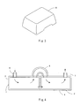
- FIG 1 is a section view shown a structure for connecting heat exchanges according to an embodiment of the present invention
- the figure 2 is a perspective view shown the structure for connecting heat exchanges according to the embodiment of the present invention.
- the first EGR cooler and the second EGR cooler are configured to be connected each other in series.
- the each EGR cooler 11, 12 essentially consists of a body part 13, 14 and heat transfer pipes 15, 16 installed in the each body part 13, 14 respectively so that heat can exchange between cooling water passing through inside of body parts 13, 14 and exhaust gasses passing through inside of heat transfer pipes 15, 16.
- a connecting hole 17, 18 is opened respectively at each end adjacent to the connecting part of the first EGR cooler 11 and the second EGR cooler 12 so that a connecting member 19 can be connected the external face of the each body part 13, 14 around the each connecting hole 17, 18 by brazing or welding.
- the connecting member 19 is formed in flat plate shape by pressing a plate member.
- a path 23 is formed between the connecting member 19 and the each body part 13, 14 by connecting the connecting member 19 to the external face of the each body part 13, 14 so that the each body part 13, 14 can go through via the path 23 and the each connecting hole 17, 18.
- a cooling water inlet pipe 20 is connected to the opposite end of the end which the connecting hole 17 of the first EGR cooler 11 is opened and also a cooling water outlet pipe 21 is connected to the opposite end of the end which the connecting hole 18 of the second EGR cooler 12 is opened.
- a header part 22 of the heat transfer pipe is formed at the connecting part between the first EGR cooler 11 and the second EGR cooler 12 so that the both heat transfer pipes 15, 16 can go thorough via the header part 22 of the heat transfer pipe.
- the connecting member 19 can be formed by press. Furthermore, it is possible to design the shape of the connecting hole 17, 18 freely to some extent such as square, oval and the like regardless of the shape of the connecting member 19 and carry out optimum design taking account of the flow and resistance of the cooling water, because the connecting member 19 is not connected to the connecting hole 17, 18 directly. In addition, it is possible to install more than two connecting members 19 since the connecting member 19 is formed in flat plate shape and large space for the installation is not required. Accordingly, in that case, it is possible to make the flow of the cooling water smooth further, improve the heat exchange efficiency and reduce the power for transferring the fluid.
- the cooling water enters into the body part 13 of the first EGR cooler 11 via the cooling water inlet pipe 20, and passes through the connecting hole 17, the path 23, the connecting hole 18. Then the cooling water comes out of the cooling water outlet pipe 21 after passing through the body part 14 of the second EGR cooler 12.
- a part of the exhaust gasses of the diesel engine pass through the heat transfer pipe 16 of the second EGR cooler 12 to the opposed direction of the flow of the cooling water. Then the exhaust gasses pass return to the an intake part of the diesel engine after passing through the first EGR cooler 11 via the header part 22 of the heat transfer pipe.
- the cooling water exchanges heat between the exhaust gases and it is cooled down at the preferred condition.
- the connecting member 19 is not limited to the above shape and may be in the other shape which can be pressed, such as vaulting horse shape and the like as shown on the figure 3.
- first EGR cooler 11 and the second EGR cooler 12 are connected in series
- present invention is applicable to the case that the each EGR cooler 11, 12 are connected in parallel, or the case that more than three EGR coolers are connected.
Landscapes
- Engineering & Computer Science (AREA)
- Physics & Mathematics (AREA)
- Thermal Sciences (AREA)
- Mechanical Engineering (AREA)
- General Engineering & Computer Science (AREA)
- Exhaust-Gas Circulating Devices (AREA)
- Heat-Exchange Devices With Radiators And Conduit Assemblies (AREA)
Applications Claiming Priority (2)
| Application Number | Priority Date | Filing Date | Title |
|---|---|---|---|
| JP2004135225A JP2007255719A (ja) | 2004-04-30 | 2004-04-30 | 熱交換器の連結構造 |
| PCT/JP2004/017250 WO2005106370A1 (ja) | 2004-04-30 | 2004-11-19 | 熱交換器の連結構造 |
Publications (2)
| Publication Number | Publication Date |
|---|---|
| EP1742005A1 true EP1742005A1 (de) | 2007-01-10 |
| EP1742005A4 EP1742005A4 (de) | 2007-11-21 |
Family
ID=35241768
Family Applications (1)
| Application Number | Title | Priority Date | Filing Date |
|---|---|---|---|
| EP04821936A Withdrawn EP1742005A4 (de) | 2004-04-30 | 2004-11-19 | Verbindungsstruktur für wärmetauscher |
Country Status (5)
| Country | Link |
|---|---|
| US (1) | US7726697B2 (de) |
| EP (1) | EP1742005A4 (de) |
| JP (1) | JP2007255719A (de) |
| CN (1) | CN1950661B (de) |
| WO (1) | WO2005106370A1 (de) |
Families Citing this family (9)
| Publication number | Priority date | Publication date | Assignee | Title |
|---|---|---|---|---|
| FR2906357B1 (fr) * | 2006-09-21 | 2013-01-18 | Valeo Systemes Thermiques | Echangeur de chaleur de type liquide/gaz,notamment pour un equipement de climatisation de vehicule automobile utilisant un fluide refrigerant operant a l'etat supercritique tel que co2 |
| WO2008136217A1 (ja) * | 2007-05-02 | 2008-11-13 | Kanken Techno Co., Ltd. | 熱交換器およびこれを用いたガス処理装置 |
| WO2008139651A1 (ja) * | 2007-05-02 | 2008-11-20 | Kanken Techno Co., Ltd. | 熱交換器およびこれを用いたガス処理装置 |
| US20100243228A1 (en) * | 2009-03-31 | 2010-09-30 | Price Richard J | Method and Apparatus to Effect Heat Transfer |
| EP2743488A1 (de) * | 2012-12-11 | 2014-06-18 | BorgWarner Inc. | Eingebaute Abgasverwaltungsvorrichtung |
| US20150057524A1 (en) * | 2013-08-22 | 2015-02-26 | Alcon Research, Ltd | Systems and methods for intra-operative eye biometry or refractive measurement |
| US9899589B2 (en) * | 2014-02-05 | 2018-02-20 | Panasonic Corporation | Thermal power generation unit and thermoelectric power generation system |
| JP2017072091A (ja) * | 2015-10-08 | 2017-04-13 | いすゞ自動車株式会社 | 車両用冷却装置 |
| KR101646761B1 (ko) * | 2016-02-03 | 2016-08-08 | 임종수 | 열교환 장치 |
Family Cites Families (8)
| Publication number | Priority date | Publication date | Assignee | Title |
|---|---|---|---|---|
| US1967466A (en) * | 1930-06-20 | 1934-07-24 | James Henry Hayes | Flexible pipe coupling |
| JPS5923580U (ja) * | 1982-07-30 | 1984-02-14 | 富士電機株式会社 | シエルアンドチユ−ブ形熱交換器 |
| US4592416A (en) * | 1985-04-29 | 1986-06-03 | The Air Preheater Company, Inc. | Modular tubular heat exchanger |
| JPS62166468U (de) * | 1986-04-08 | 1987-10-22 | ||
| JP3885904B2 (ja) * | 1997-05-06 | 2007-02-28 | 臼井国際産業株式会社 | Egrガス冷却装置 |
| JP2000088150A (ja) | 1998-09-16 | 2000-03-31 | Toshiomi Hayashi | 配管類の組立方法及び組立構造 |
| JP2002005584A (ja) * | 2000-06-23 | 2002-01-09 | Takuma Co Ltd | 熱交換器 |
| DE20318321U1 (de) * | 2003-11-06 | 2004-03-04 | Mtu Friedrichshafen Gmbh | Abgaswärmetauscher |
-
2004
- 2004-04-30 JP JP2004135225A patent/JP2007255719A/ja active Pending
- 2004-11-19 WO PCT/JP2004/017250 patent/WO2005106370A1/ja not_active Ceased
- 2004-11-19 CN CN2004800427181A patent/CN1950661B/zh not_active Expired - Fee Related
- 2004-11-19 EP EP04821936A patent/EP1742005A4/de not_active Withdrawn
- 2004-11-19 US US11/579,211 patent/US7726697B2/en not_active Expired - Fee Related
Also Published As
| Publication number | Publication date |
|---|---|
| CN1950661A (zh) | 2007-04-18 |
| US7726697B2 (en) | 2010-06-01 |
| JP2007255719A (ja) | 2007-10-04 |
| US20080000461A1 (en) | 2008-01-03 |
| EP1742005A4 (de) | 2007-11-21 |
| CN1950661B (zh) | 2011-04-27 |
| WO2005106370A1 (ja) | 2005-11-10 |
Similar Documents
| Publication | Publication Date | Title |
|---|---|---|
| US8069905B2 (en) | EGR gas cooling device | |
| KR101341469B1 (ko) | 이중 냉각제 루프를 가지는 배기가스 재순환 쿨러 | |
| US20070193732A1 (en) | Heat exchanger | |
| CN101313192A (zh) | 用于内燃机的热交换器 | |
| JP2009512832A (ja) | 熱交換器 | |
| JP2004028535A (ja) | 排気熱交換装置 | |
| EP1742005A1 (de) | Verbindungsstruktur für wärmetauscher | |
| AU2003260548A1 (en) | Heat exchange module with a principal radiator and two secondary radiators | |
| JP3956097B2 (ja) | 排気熱交換装置 | |
| EP1996891B1 (de) | Wärmetauscher für agr-gas | |
| FR2886391B1 (fr) | Echangeur de chaleur comportant un faisceau d'echange de chaleur loge dans un boitier | |
| JP3893895B2 (ja) | Egrガス冷却構造 | |
| CN202300586U (zh) | 冷却装置 | |
| JP6481275B2 (ja) | コルゲートフィン式熱交換器 | |
| JP2005055153A (ja) | 熱交換器 | |
| CN211975217U (zh) | 一种高效板翅式egr冷却器 | |
| JP4681435B2 (ja) | 熱交換器の連結構造 | |
| JP2012067955A (ja) | 熱交換器及びそれを用いたエンジンの吸気冷却装置 | |
| US7290391B2 (en) | Charge air cooler designed for tier 2 locomotive diesel engine | |
| JP2004077024A (ja) | 排気熱交換装置 | |
| JP3156355U (ja) | 2重管式熱交換器 | |
| EP3719431A2 (de) | Ladeluftkühler | |
| CN2648372Y (zh) | 管片式散热器 | |
| CN208441922U (zh) | 换热器和包括该换热器的车用中冷器 | |
| CN202660816U (zh) | 一种平行流换热器 |
Legal Events
| Date | Code | Title | Description |
|---|---|---|---|
| PUAI | Public reference made under article 153(3) epc to a published international application that has entered the european phase |
Free format text: ORIGINAL CODE: 0009012 |
|
| 17P | Request for examination filed |
Effective date: 20060928 |
|
| AK | Designated contracting states |
Kind code of ref document: A1 Designated state(s): CZ DE IT |
|
| DAX | Request for extension of the european patent (deleted) | ||
| RBV | Designated contracting states (corrected) |
Designated state(s): CZ DE IT |
|
| A4 | Supplementary search report drawn up and despatched |
Effective date: 20071023 |
|
| 17Q | First examination report despatched |
Effective date: 20090406 |
|
| GRAP | Despatch of communication of intention to grant a patent |
Free format text: ORIGINAL CODE: EPIDOSNIGR1 |
|
| STAA | Information on the status of an ep patent application or granted ep patent |
Free format text: STATUS: THE APPLICATION IS DEEMED TO BE WITHDRAWN |
|
| 18D | Application deemed to be withdrawn |
Effective date: 20100220 |