EP1742067A2 - Dispositif pour la détection de la vitesse et de la position d'un arbre tournant - Google Patents
Dispositif pour la détection de la vitesse et de la position d'un arbre tournant Download PDFInfo
- Publication number
- EP1742067A2 EP1742067A2 EP06122757A EP06122757A EP1742067A2 EP 1742067 A2 EP1742067 A2 EP 1742067A2 EP 06122757 A EP06122757 A EP 06122757A EP 06122757 A EP06122757 A EP 06122757A EP 1742067 A2 EP1742067 A2 EP 1742067A2
- Authority
- EP
- European Patent Office
- Prior art keywords
- data
- values
- loop
- program
- digitalization
- Prior art date
- Legal status (The legal status is an assumption and is not a legal conclusion. Google has not performed a legal analysis and makes no representation as to the accuracy of the status listed.)
- Withdrawn
Links
- 238000000034 method Methods 0.000 title claims abstract description 16
- 238000001514 detection method Methods 0.000 claims abstract description 8
- 230000010354 integration Effects 0.000 claims abstract description 4
- 238000004364 calculation method Methods 0.000 claims abstract description 3
- 238000001914 filtration Methods 0.000 claims abstract description 3
- 230000009466 transformation Effects 0.000 claims description 6
- 230000003321 amplification Effects 0.000 claims 2
- 238000003199 nucleic acid amplification method Methods 0.000 claims 2
- 238000004590 computer program Methods 0.000 claims 1
- 238000006243 chemical reaction Methods 0.000 description 3
- 238000010586 diagram Methods 0.000 description 2
- 230000006698 induction Effects 0.000 description 2
- 230000006870 function Effects 0.000 description 1
- 230000003993 interaction Effects 0.000 description 1
- 230000007246 mechanism Effects 0.000 description 1
- 230000003068 static effect Effects 0.000 description 1
Images
Classifications
-
- G—PHYSICS
- G01—MEASURING; TESTING
- G01P—MEASURING LINEAR OR ANGULAR SPEED, ACCELERATION, DECELERATION, OR SHOCK; INDICATING PRESENCE, ABSENCE, OR DIRECTION, OF MOVEMENT
- G01P3/00—Measuring linear or angular speed; Measuring differences of linear or angular speeds
- G01P3/42—Devices characterised by the use of electric or magnetic means
- G01P3/44—Devices characterised by the use of electric or magnetic means for measuring angular speed
- G01P3/48—Devices characterised by the use of electric or magnetic means for measuring angular speed by measuring frequency of generated current or voltage
- G01P3/481—Devices characterised by the use of electric or magnetic means for measuring angular speed by measuring frequency of generated current or voltage of pulse signals
- G01P3/487—Devices characterised by the use of electric or magnetic means for measuring angular speed by measuring frequency of generated current or voltage of pulse signals delivered by rotating magnets
-
- G—PHYSICS
- G01—MEASURING; TESTING
- G01P—MEASURING LINEAR OR ANGULAR SPEED, ACCELERATION, DECELERATION, OR SHOCK; INDICATING PRESENCE, ABSENCE, OR DIRECTION, OF MOVEMENT
- G01P3/00—Measuring linear or angular speed; Measuring differences of linear or angular speeds
- G01P3/42—Devices characterised by the use of electric or magnetic means
- G01P3/44—Devices characterised by the use of electric or magnetic means for measuring angular speed
- G01P3/48—Devices characterised by the use of electric or magnetic means for measuring angular speed by measuring frequency of generated current or voltage
- G01P3/481—Devices characterised by the use of electric or magnetic means for measuring angular speed by measuring frequency of generated current or voltage of pulse signals
- G01P3/489—Digital circuits therefor
Definitions
- the present invention relates to a method for detecting the speed and the position of a rotating shaft.
- a magnetic member is positioned on the movable part of the device, integral with the rotating shaft, and sensors means detect the magnetic field thereof.
- an object of the present invention is to provide a method for determining the speed and the position of a rotating shaft which could be simply implemented on a standard processing unit.
- the present invention relates to a method for determining the speed and the position of a rotating shaft, comprising the detection of a series of values relating to vectorial parameters within a given time interval, the digitalization of said values, the processing of said values by means of a suitable program which envisages the software implementation of a phase lock loop comprising: the conversion of the digitalized data, the error calculation on the basis of the data within the loop, the adjustment/filtration of the data, the integration of the data and the reintroduction of the data into the loop, suitably adapted to data scale factors, the angular velocity and angular position values of said shaft being retrieved for each instant.
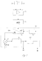
- the signal supplied by the two sensors 113 namely a sinusoidal voltage, resulting from the sinusoidal character of the magnetic field of the member 202, is amplified at 20 in such a way as to adjust all the data obtained within the range of 0-5 V suitable for analog/digital conversion (21) into data with 10-bit resolution.
- the digitalized data then undergoes the processing step (indicated by the broken line 30) consisting in software implementation of a phase lock loop; Park's transformation (31) is applied to the data introduced after digitalization together with that generated in the loop.
- the comparison (32) results in determination of the error between the two series of data; after suitable adjustment (33), the first result which is obtained is the angular velocity w and, thereafter, following integration (34) the electrical position ⁇ of the shaft is obtained.
- This data, after suitable readaptation (35), is introduced again into the loop for comparison with the new digitalized data supplied by the sensors 113.
- the phase lock loop is a control system, the aim of which is synchronization of the instantaneous angle, or the phase and the frequency, of a signal generated locally with a signal provided at the input, also called a reference signal.
- PLL an abbreviation of Phase Lock Loop
- Synchronization of the instantaneous angle is performed by means of comparison of the phases. Once this state has been achieved, the phase error between the reference signal and the signal generated locally is very small or zero. If this error, owing to a disturbance or a variation of the input signal, starts to increase, the control mechanism responds, altering its own operating state, so as to reset the value thereof.
- the components of a PLL in a configuration of a generic type are: a phase comparator or detector (PD), a loop filter (LF) and a voltage controlled oscillator (VCO).
- the components of the phase lock loop are implemented on a software level by suitable operators; Park's transformation (31) performs the task of a phase comparator, the adjusting proportional integrator (33) performs the function of the loop filter and the integrator (34) that of the controlled voltage oscillator.
- Park's transformation which historically was devised for studying the dynamics of rotating electric machines, is commonly used in this sector; in this case the transformation was applied to rotating shafts.
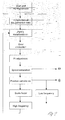
- Figure 2 shows in greater detail the main processing steps which form the program used in the method according to the present invention; the values detected and amplified as described above are digitalized and memorized; then they are processed using Park's transformation together with the data supplied by the loop.
- convergence of the two sets of data namely minimization of the error generated, after adjustment by means of the proportional integrator, detection of the speed is performed, and the angular position is obtained by integrating this data.
- the data which is reintroduced into the cycle of the phase lock loop is rebalanced by means of a scale factor which takes into account the electrical frequency ratio which exists between the sensors and the induction motor which move the rotating axis.
- the low frequency data is thus used to monitor the electric frequency of the induction motor, while the normalised high frequency data is reintroduced into the phase lock loop.
- the program described above may be realized in different computer languages; in a preferred embodiment assembly language was chosen.
- the central processing unit which comprises the amplifier means 20, the analog/digital conversion means 21 and the processor means in which the phase lock loop was implemented, may be positioned both in the machine to be monitored in the vicinity of the sensor means, or incorporated into the static part of said sensor, and in the power supply and control panel of said machine.
Landscapes
- Physics & Mathematics (AREA)
- General Physics & Mathematics (AREA)
- Transmission And Conversion Of Sensor Element Output (AREA)
- Measurement Of Length, Angles, Or The Like Using Electric Or Magnetic Means (AREA)
Applications Claiming Priority (2)
| Application Number | Priority Date | Filing Date | Title |
|---|---|---|---|
| IT000045A ITGE20040045A1 (it) | 2004-05-21 | 2004-05-21 | Dispositivo per rilevamento della velocita' e della posizione di assi rotanti. |
| EP05103886A EP1598672A3 (fr) | 2004-05-21 | 2005-05-10 | Dispositif pour la détection de la vitesse et de la position d'un arbre tournant |
Related Parent Applications (1)
| Application Number | Title | Priority Date | Filing Date |
|---|---|---|---|
| EP05103886A Division EP1598672A3 (fr) | 2004-05-21 | 2005-05-10 | Dispositif pour la détection de la vitesse et de la position d'un arbre tournant |
Publications (1)
| Publication Number | Publication Date |
|---|---|
| EP1742067A2 true EP1742067A2 (fr) | 2007-01-10 |
Family
ID=34939766
Family Applications (2)
| Application Number | Title | Priority Date | Filing Date |
|---|---|---|---|
| EP06122757A Withdrawn EP1742067A2 (fr) | 2004-05-21 | 2005-05-10 | Dispositif pour la détection de la vitesse et de la position d'un arbre tournant |
| EP05103886A Withdrawn EP1598672A3 (fr) | 2004-05-21 | 2005-05-10 | Dispositif pour la détection de la vitesse et de la position d'un arbre tournant |
Family Applications After (1)
| Application Number | Title | Priority Date | Filing Date |
|---|---|---|---|
| EP05103886A Withdrawn EP1598672A3 (fr) | 2004-05-21 | 2005-05-10 | Dispositif pour la détection de la vitesse et de la position d'un arbre tournant |
Country Status (3)
| Country | Link |
|---|---|
| US (1) | US20050261868A1 (fr) |
| EP (2) | EP1742067A2 (fr) |
| IT (1) | ITGE20040045A1 (fr) |
Families Citing this family (4)
| Publication number | Priority date | Publication date | Assignee | Title |
|---|---|---|---|---|
| DE102008040530A1 (de) * | 2008-07-18 | 2010-01-21 | Robert Bosch Gmbh | Ermitteln einer Drehzahl einer elektrischen Maschine |
| KR20130111519A (ko) * | 2010-06-10 | 2013-10-10 | 콘티넨탈 테베스 아게 운트 코. 오하게 | 코스타스 루프를 포함하는 속도 센서 |
| EP2580600B2 (fr) | 2010-06-10 | 2019-04-17 | Continental Teves AG & Co. OHG | Ensemble capteur pour mesurer une vitesse |
| TWI479155B (zh) * | 2013-03-29 | 2015-04-01 | Kwang Yang Motor Co | Locomotive wheel speed induction device |
Family Cites Families (8)
| Publication number | Priority date | Publication date | Assignee | Title |
|---|---|---|---|---|
| DE4036024C1 (fr) * | 1990-11-13 | 1992-02-27 | Heidelberger Druckmaschinen Ag, 6900 Heidelberg, De | |
| DE4137559A1 (de) * | 1991-11-15 | 1993-05-19 | Heidelberger Druckmasch Ag | Einrichtung zur erfassung mindestens einer zustandsgroesse eines buerstenlosen gleichstrommotors |
| DE4315637C2 (de) * | 1993-05-11 | 1996-12-19 | Brose Fahrzeugteile | Verfahren zur Erkennung der Position und der Bewegungsrichtung eines bewegbar gelagerten Teils |
| US5805464A (en) * | 1995-06-15 | 1998-09-08 | Dynamics Research Corp. | Dynamic balancer electronic angle finder |
| EP1083406A3 (fr) * | 1999-09-09 | 2002-03-20 | Delphi Technologies, Inc. | Capteur de position rotative |
| JP4249916B2 (ja) * | 2000-09-18 | 2009-04-08 | エドワーズ株式会社 | ブラシレスモータの制御回路、ブラシレスモータ装置、及び真空ポンプ装置 |
| NL1019828C2 (nl) * | 2002-01-24 | 2003-07-25 | Skf Ab | Rotatiesnelheidsensor. |
| US20040217758A1 (en) * | 2003-05-02 | 2004-11-04 | Leonard John R. | Electromagnetic shaft position sensor and method |
-
2004
- 2004-05-21 IT IT000045A patent/ITGE20040045A1/it unknown
-
2005
- 2005-05-10 EP EP06122757A patent/EP1742067A2/fr not_active Withdrawn
- 2005-05-10 EP EP05103886A patent/EP1598672A3/fr not_active Withdrawn
- 2005-05-18 US US11/131,375 patent/US20050261868A1/en not_active Abandoned
Also Published As
| Publication number | Publication date |
|---|---|
| ITGE20040045A1 (it) | 2004-08-21 |
| EP1598672A3 (fr) | 2006-02-08 |
| EP1598672A2 (fr) | 2005-11-23 |
| US20050261868A1 (en) | 2005-11-24 |
Similar Documents
| Publication | Publication Date | Title |
|---|---|---|
| US5760510A (en) | Magnetic bearing device | |
| US12181311B2 (en) | Clutch actuator, sensing system and method for sensing an angular position of a rotational component | |
| EP1705792A1 (fr) | Moteur sans balai avec circuit de commande | |
| US20140356126A1 (en) | Method and system for synchronously inhibiting subcritical vibrations of magnetic levitation molecular pump rotor | |
| CN105008003B (zh) | 用于电子换相电机的带参比探测器的转子位置探测器 | |
| CN109343506B (zh) | 一种磁悬浮轴承控制器检测方法、系统及应用 | |
| US20210159822A1 (en) | Method for determining an angular position of a rotating component, in particular of an electric motor for a clutch actuation system of a vehicle | |
| CN107202016B (zh) | 磁轴承式真空泵 | |
| EP1742067A2 (fr) | Dispositif pour la détection de la vitesse et de la position d'un arbre tournant | |
| CN105509684A (zh) | 轴向位移的检测方法、装置及系统 | |
| CN106877588A (zh) | 用于降低振动和噪声的转子定向装置 | |
| KR101883530B1 (ko) | 회전 자계 기계의 속도 및 로터 위치를 검출하기 위한 방법 및 장치 | |
| US5496254A (en) | Lab centrifuge with imbalance shutoff | |
| US8525452B2 (en) | Counter electro-motoric force based functional status detection of an electro-motor | |
| CN115199646B (zh) | 一种磁悬浮系统及其控制方法、装置和存储介质 | |
| JP3222403B2 (ja) | 磁気軸受の制御装置 | |
| JP2021061695A (ja) | モーターの異常検出装置及びこれを備えた車両 | |
| JP3457353B2 (ja) | 磁気軸受装置 | |
| JPH1037958A (ja) | 磁気軸受装置 | |
| JP3700527B2 (ja) | サーボ制御システム、電子機器及びゲイン調整方法 | |
| CN117642599A (zh) | 用于测量在离心力载荷下旋转转子的参照转子角度的扩径的方法 | |
| JP3129872B2 (ja) | 高速タイヤユニフォミティマシンによるアンバランス補正方法 | |
| JP2002315374A (ja) | モータ制御装置 | |
| US6259178B1 (en) | Initial adjustment circuit and initial adjustment method of magnetic bearing apparatus | |
| CN113646618B (zh) | 用于控制转速的方法和控制装置 |
Legal Events
| Date | Code | Title | Description |
|---|---|---|---|
| PUAI | Public reference made under article 153(3) epc to a published international application that has entered the european phase |
Free format text: ORIGINAL CODE: 0009012 |
|
| AC | Divisional application: reference to earlier application |
Ref document number: 1598672 Country of ref document: EP Kind code of ref document: P |
|
| AK | Designated contracting states |
Kind code of ref document: A2 Designated state(s): AT BE BG CH CY CZ DE DK EE ES FI FR GB GR HU IE IS IT LI LT LU MC NL PL PT RO SE SI SK TR |
|
| STAA | Information on the status of an ep patent application or granted ep patent |
Free format text: STATUS: THE APPLICATION IS DEEMED TO BE WITHDRAWN |
|
| 18D | Application deemed to be withdrawn |
Effective date: 20101201 |