EP1742207A2 - Optisches Datenspeichermedium für einmal beschreibbare Aufzeichnung - Google Patents
Optisches Datenspeichermedium für einmal beschreibbare Aufzeichnung Download PDFInfo
- Publication number
- EP1742207A2 EP1742207A2 EP06114865A EP06114865A EP1742207A2 EP 1742207 A2 EP1742207 A2 EP 1742207A2 EP 06114865 A EP06114865 A EP 06114865A EP 06114865 A EP06114865 A EP 06114865A EP 1742207 A2 EP1742207 A2 EP 1742207A2
- Authority
- EP
- European Patent Office
- Prior art keywords
- stack
- layer
- recording
- dual
- data storage
- Prior art date
- Legal status (The legal status is an assumption and is not a legal conclusion. Google has not performed a legal analysis and makes no representation as to the accuracy of the status listed.)
- Withdrawn
Links
Images






Classifications
-
- G—PHYSICS
- G11—INFORMATION STORAGE
- G11B—INFORMATION STORAGE BASED ON RELATIVE MOVEMENT BETWEEN RECORD CARRIER AND TRANSDUCER
- G11B7/00—Recording or reproducing by optical means, e.g. recording using a thermal beam of optical radiation by modifying optical properties or the physical structure, reproducing using an optical beam at lower power by sensing optical properties; Record carriers therefor
- G11B7/24—Record carriers characterised by shape, structure or physical properties, or by the selection of the material
- G11B7/2403—Layers; Shape, structure or physical properties thereof
- G11B7/24035—Recording layers
- G11B7/24038—Multiple laminated recording layers
-
- G—PHYSICS
- G11—INFORMATION STORAGE
- G11B—INFORMATION STORAGE BASED ON RELATIVE MOVEMENT BETWEEN RECORD CARRIER AND TRANSDUCER
- G11B7/00—Recording or reproducing by optical means, e.g. recording using a thermal beam of optical radiation by modifying optical properties or the physical structure, reproducing using an optical beam at lower power by sensing optical properties; Record carriers therefor
- G11B7/007—Arrangement of the information on the record carrier, e.g. form of tracks, actual track shape, e.g. wobbled, or cross-section, e.g. v-shaped; Sequential information structures, e.g. sectoring or header formats within a track
-
- G—PHYSICS
- G11—INFORMATION STORAGE
- G11B—INFORMATION STORAGE BASED ON RELATIVE MOVEMENT BETWEEN RECORD CARRIER AND TRANSDUCER
- G11B7/00—Recording or reproducing by optical means, e.g. recording using a thermal beam of optical radiation by modifying optical properties or the physical structure, reproducing using an optical beam at lower power by sensing optical properties; Record carriers therefor
- G11B7/24—Record carriers characterised by shape, structure or physical properties, or by the selection of the material
-
- G—PHYSICS
- G11—INFORMATION STORAGE
- G11B—INFORMATION STORAGE BASED ON RELATIVE MOVEMENT BETWEEN RECORD CARRIER AND TRANSDUCER
- G11B7/00—Recording or reproducing by optical means, e.g. recording using a thermal beam of optical radiation by modifying optical properties or the physical structure, reproducing using an optical beam at lower power by sensing optical properties; Record carriers therefor
- G11B7/24—Record carriers characterised by shape, structure or physical properties, or by the selection of the material
- G11B7/241—Record carriers characterised by shape, structure or physical properties, or by the selection of the material characterised by the selection of the material
- G11B7/242—Record carriers characterised by shape, structure or physical properties, or by the selection of the material characterised by the selection of the material of recording layers
- G11B7/244—Record carriers characterised by shape, structure or physical properties, or by the selection of the material characterised by the selection of the material of recording layers comprising organic materials only
- G11B7/246—Record carriers characterised by shape, structure or physical properties, or by the selection of the material characterised by the selection of the material of recording layers comprising organic materials only containing dyes
-
- G—PHYSICS
- G11—INFORMATION STORAGE
- G11B—INFORMATION STORAGE BASED ON RELATIVE MOVEMENT BETWEEN RECORD CARRIER AND TRANSDUCER
- G11B7/00—Recording or reproducing by optical means, e.g. recording using a thermal beam of optical radiation by modifying optical properties or the physical structure, reproducing using an optical beam at lower power by sensing optical properties; Record carriers therefor
- G11B7/08—Disposition or mounting of heads or light sources relatively to record carriers
- G11B7/09—Disposition or mounting of heads or light sources relatively to record carriers with provision for moving the light beam or focus plane for the purpose of maintaining alignment of the light beam relative to the record carrier during transducing operation, e.g. to compensate for surface irregularities of the latter or for track following
- G11B7/0938—Disposition or mounting of heads or light sources relatively to record carriers with provision for moving the light beam or focus plane for the purpose of maintaining alignment of the light beam relative to the record carrier during transducing operation, e.g. to compensate for surface irregularities of the latter or for track following servo format, e.g. guide tracks, pilot signals
Definitions
- the invention relates to a dual-stack optical data storage medium for write-once recording using a focused radiation beam having a wavelength ⁇ and entering through an entrance face of the medium during recording, comprising:
- DVD Digital Versatile Disk
- ROM read only
- R recordable
- RW rewritable
- DVD+R DVD-R for recordable and DVD+RW
- DVD-RW DVD-RAM for rewritable.
- An issue for both the recordable and rewritable DVD formats is the limited capacity and therefore recording time because only single-stacked media are present with a maximum capacity of 4.7 GB.
- DVD-Video which is a ROM disk
- dual layer media with 8.5 GB capacity often referred to as DVD-9
- DVD-9 recordable and rewritable DVD's with 8.5GB capacity are highly desired.
- a dual-layer, i.e. dual-stack, rewritable DVD disk is probably feasible.
- a rewritable fully compatible disk i.e. within the reflection and modulation specification of the dual-layer DVD-ROM, is very difficult to achieve and requires at least a major breakthrough for the properties of the amorphous/crystalline phase-change materials, which are used as recording layers in rewritable DVD media.
- Typical achievable effective reflection levels are about 7%; such low reflection values severely reduce read-back compatibility on existing DVD-players. Without a full compatibility, the success of a dual-layer rewritable DVD in the market is questionable.
- Effective optical reflection means that the reflection is measured as the portion of effective light coming back from the medium when e.g. both stacks L 0 and L 1 are present and focusing on L 0 and L 1 respectively.
- a somewhat lower effective reflection e.g. R>0.12, is acceptable to achieve read-out compatibility in existing DVD-players. Note that such a reflectivity of R>0.12 is, at present, not achievable in a rewritable dual-stack DVD based on e.g. phase-change technology.
- L 0 is defined as the "closest" stack, i.e. closest to the radiation beam entrance face, and L 1 is the deepest stack, as seen from the radiation beam entrance face.
- optical data storage medium which is characterized in that 0.45 ⁇ T L0 ⁇ 0.75 and 0.40 ⁇ R L1 ⁇ 0.80 and k L0 ⁇ 0.3 and k L1 ⁇ 0.3.
- these requirements may be deduced from the requirement that the effective reflection levels from both recording stacks L 0 and L 1 are larger than 12%. More preferably 0.55 ⁇ T L0 ⁇ 0.65 and 0.50 ⁇ R L1 ⁇ 0.70 and k L0 ⁇ 0.2 and k L1 ⁇ 0.2 in which case even higher effective reflection values may be achieved e.g. 15% or 18%.
- a dual-stack recordable DVD medium e.g.
- DVD+R based on a recording layer with write once technology, having a relatively low optical absorption can in principle overcome the reflection-problem of the phase-change rewritable DVD dual stack medium.
- a write-once recording layer with a relatively low absorption is e.g. a dye layer.
- the present invention can be applied to both the DVD+R and DVD-R formats. In the following, we will use DVD+R to indicate a recordable DVD in general.
- the typical single stack DVD+R medium has a reflectivity of 50% and a modulation of 60%; these values are within the single stack DVD-ROM specification; DVD+RW media have much lower reflectivity of about 20%.
- the starting point for developing a dual-stack R-medium is thus much more favorable than for RW media.
- the dye material intrinsically has a high transmission at the wavelength ⁇ . In combination with a metal reflective layer, a high reflectivity can be achieved. Thus, recording is possible with a relatively low absorption in the dye layer.
- Typical dyes that can be used are cyanine-type, azo-type, squarylium-type, or other organic dye material having the desired properties.
- Figure 1 shows that a compatible dual stack DVD+R medium is in principle possible when assuming reasonable numbers for transmission and absorption of recording, e.g. dye, stacks. A reflection of larger than 18% per stack is possible if the transmission of the upper recording stack L 0 is between 45% and 75%; the intrinsic reflection of the lower recording stack L 1 should then be in the range 40% - 80%.
- Figure 1b illustrates this fact in more detail.
- ⁇ is approximately 655 nm.
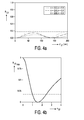
- Fig. 4a shows the calculated reflectivity for a recording layer-only stack as a function of the L 0 recording layer thickness d L0 .
- the reflectivity therefore determines the required optical parameters and layer thickness.
- n L0 ⁇ 2.5 and d L0 is in the range of ⁇ /8n L0 ⁇ d L0 ⁇ 3 ⁇ /8n L0 or 5 ⁇ /8n L0 ⁇ d L0 ⁇ 7 ⁇ /8n L0 .
- the optimal L 0 recording layer thickness d L0 is at the first or second maximum in reflectivity, the preferred layer thickness is then: ⁇ / 8 ⁇ n L ⁇ 0 ⁇ d L ⁇ 0 ⁇ 3 ⁇ ⁇ / 8 L ⁇ 0 1 st max 5 ⁇ ⁇ / 8 ⁇ n L ⁇ 0 ⁇ d L ⁇ 0 ⁇ 7 ⁇ ⁇ / 8 ⁇ n L ⁇ 0 2 nd max
- the advantages of this L 0 stack design are a high transparency and its simplicity.
- a first metal reflective layer having a thickness d M1 ⁇ 25 nm, is present between the write-once L 0 recording layer and the transparent spacer layer and d L0 is in the range of ⁇ /8n L0 ⁇ d L0 ⁇ 5 ⁇ /8n L0 .
- a relatively thin first metal reflective layer is placed between the dye and the spacer.
- the first metal reflective layer serves as a semi-transparent layer to increase the reflectivity.
- a maximum thickness and suitable material must be specified to keep the transmission of the first metal reflective layer sufficiently high.
- the metal layer e.g. Ag, Au, Cu, Al, or alloys thereof, or doped with other elements, can be used.
- the preferred thickness of the metal layer is: d M ⁇ 1 ⁇ 25 nm
- the optimum dye-layer thickness is determined by both the maxima in transmission and reflection.
- the preferred dye layer thickness range becomes: ⁇ / 8 ⁇ n L ⁇ 0 ⁇ d L ⁇ 0 ⁇ 5 ⁇ ⁇ / 8 ⁇ n L ⁇ 0 .
- a first transparent auxiliary layer I1 having a refractive index n I1 ⁇ 1.8 and having a thickness d I1 ⁇ ⁇ /2n I1 , is present between the first metal reflective layer and the transparent spacer layer.
- a first transparent auxiliary layer I1 e.g. a dielectric interference layer
- the transmission near the optimum reflectivity is increased; the role of the dielectric I-layer is to counteract the optical mismatch between the "recording layer + thin metal" stack and the substrate, e.g. made of polycarbonate, and thereby lower the reflection and raise the transmission.
- the only useful stack design is recording layer/thin-metal/I-layer, which can have high T, finite R, and sufficient absorption in the recording layer at the same time.
- the first metal reflective layer e.g. Ag, Au, Cu, Al or alloys thereof, or doped with other elements.
- the preferred thickness of the metal layer for this stack type is: d M ⁇ 1 ⁇ 25 nm
- the first auxiliary layer I1 below the first metal reflective layer indeed increases the stack's transmission and decreases its reflectivity, while the position of the R- and T-extrema stays (nearly) the same.
- the optimum recording layer thickness is determined by the first maximum in reflection, which is given by Max(R) ⁇ /2n L0 (1 - ⁇ ), where ⁇ ⁇ 1/8 to 1/4 is a phase shift introduced by the metal.
- the preferred recording layer thickness for this stack becomes: ⁇ / 8 ⁇ n L ⁇ 0 ⁇ d L ⁇ 0 ⁇ 5 ⁇ ⁇ / 8 ⁇ n L ⁇ 0
- d I1 ⁇ ⁇ /4n I1 It is preferred that d I1 ⁇ ⁇ /4n I1 . It appears that the relative increase in T that can be gained by the first auxiliary I1-layer depends on the I1-layer's refractive index and on the metal reflective layer thickness, while the properties of the recording layer do not influence the relative increase of T. As shown in Fig 11, the useful range of refractive indices n I of the I-layer is n I ⁇ 1 ⁇ 1.8
- the minimal refractive index of the I1-layer is for which an increase by a factor X in transmission of the bare recording layer/thin-metal-reflective layer stack can be gained. It follows that for an X-gain in transmission the I-layer's refractive index should be: n I ⁇ 1 ⁇ X + 0.036 ⁇ d M ⁇ 1 ⁇ 1.025 / 0.0267 ⁇ d M ⁇ 1 + 0.005
- the first metal reflective layer thickness d M1 is given in nanometers (note that the formula is an approximation in the range of n I1 of 1.8 - 3).
- the reflection and transmission of the stack are also periodic in the thickness of the lower-lying interference layer, with period ⁇ /2n I1 . Therefore, the I1-layer thickness need not be larger than one period: d I ⁇ 1 ⁇ ⁇ / 2 ⁇ n I ⁇ 1
- the I1-layer is intended to increase T (and decrease R) it's optimal thickness lies at the position of the first maximum in T which is located at (1/2 - ⁇ )* ⁇ /2n I1 , with ⁇ ⁇ 1/8.
- n I1 For larger d I1 the transmission decreases and the reflection increases again. If n I1 is sufficiently large, it is possible to keep the I1-layer's thickness below the optimum value given above.
- the useful thickness range of the I-layer then becomes: d I ⁇ 1 ⁇ ⁇ / 4 ⁇ n I ⁇ 1
- the advantage of this design is its flexibility, i.e. a large range of R and T is possible.
- a second transparent auxiliary layer I2 having a refractive index n I2 and having a thickness d I2 in the range of 0 ⁇ d I2 ⁇ 3 ⁇ /8n I2 , is present at a side of the write-once L 0 recording layer and d L0 is in the range of ⁇ /8n L0 ⁇ d L0 ⁇ 3 ⁇ /8n L0 or 5 ⁇ /8n L0 ⁇ d L0 ⁇ 7 ⁇ /8n L0 .
- the second transparent auxiliary layer is present at a side of the write-once L 0 recording layer most remote from the entrance face and n I2 ⁇ n L0 /1.572.
- the second transparent auxiliary layer is present at a side of the write-once L 0 recording layer closest to the entrance face and n I2 ⁇ n L0 /0.636. No metal reflective layer is present.
- This stack is based on the principle of a dielectric mirror. Since the second auxiliary I2-layer, i.e. the dielectric mirror, is transparent, the requirements for recording- and I-layer thickness and optical constants follow from the reflectivity constraint.
- the reflectivity is maximized when the interference layer is ⁇ /4n I2 (or 3 ⁇ /4n I2 ) thick and the dye layer ⁇ /4n L0 (1 st max) or 3 ⁇ /4n L0 (2 nd max).
- the preferred range of the interference layer thickness is: 0 ⁇ d I ⁇ 2 ⁇ 3 ⁇ ⁇ / 8 ⁇ n I ⁇ 2
- the preferred thickness range for the dye layer is: ⁇ / 8 ⁇ n L ⁇ 0 ⁇ d L ⁇ 0 ⁇ 3 ⁇ ⁇ / 8 ⁇ n L ⁇ 0 1 st ⁇ max 5 ⁇ ⁇ / 8 ⁇ n L ⁇ 0 ⁇ d L ⁇ 0 ⁇ 7 ⁇ ⁇ / 8 ⁇ n L ⁇ 0 2 nd ⁇ max
- the I2-layer's refractive index can be calculated to be: n I ⁇ 2 ⁇ n L ⁇ 0 / 1.572
- the I2-layer's refractive index can be calculated to be: n I ⁇ 2 ⁇ n L ⁇ 0 / 0.636
- the reflective properties of the stack can be improved using less extreme values of the refractive indices of the I2-layers.
- the stack becomes more complicated then.
- the advantage of the design described above is its relative simplicity while still sufficient reflection and high transmission are achieved.
- the stacks proposed for L 0 are not restricted to use in dual-stack media, but can be used in single-stack and multi-stack (>2) media as well.
- a second metal reflective layer is present at a side of the write-once type L 1 recording layer most remote from the entrance face.
- the second metal reflective layer has a thickness d M2 ⁇ 25 nm and preferably d L1 is in the range of 0 ⁇ d L1 ⁇ 3 ⁇ /4n L1 .
- the latter range is the range of a conventional single stack write once medium.
- d M2 is lower than 25 nm the reflectivity may become too low.
- the lower L 1 stack of a recordable dual-stack DVD medium should have high reflectivity at the radiation beam wavelength in order to be able to read back recorded data through the above L 0 stack.
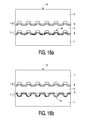
- the effective reflectivity of L 1 should be in the range of 18% to 30%. If the L 0 stack has a transmission at the laser wavelength of T L1 , this means that the intrinsic reflection of L 1 should be in the range 18/T L0 2 % to 30/T L0 2 %. Given typical transmission of L 0 in the range 50% to 60%, this implies that L 1 's reflectivity should be 50% or more. This value already falls within the reflectivity-range specified for single-stack DVD+R discs. Thus in principle a single-stack DVD+R stack design can be used as the L 1 -stack. However, in the case of type 2 (see Fig. 16b) discs, this implies that the recording layer, e.g. the dye is in direct contact with e.g. the adhesive for the spacer layer. This adhesive can possibly harm the dye, resulting in poor medium lifetimes.
- the recording layer e.g. the dye is in direct contact with e.g. the adhesive for the spacer layer. This adhesive can possibly harm the
- a third transparent auxiliary layer I3, having a refractive index n I3 and having a thickness d I3 in the range 0 ⁇ d I3 ⁇ ⁇ /n I3 is present adjacent the write-once type L 1 recording layer at a side of the write-once type L 1 recording layer closest to the entrance face or that a third metal reflective layer, having a thickness d M3 in the range of 0 ⁇ d M3 ⁇ 25 nm, is present adjacent the write-once L 1 recording layer at a side closest to the entrance face and d L1 is in the range of 0 ⁇ d L1 ⁇ 5 ⁇ /16n L1 or 7 ⁇ /16n L1 ⁇ d L1 ⁇ ⁇ /n L1 .
- the third transparent auxiliary layer or third metal reflective layer By introducing the third transparent auxiliary layer or third metal reflective layer the problem of chemical influence of the spacer layer to the recording layer is counteracted.
- Two L 1 stack types are proposed here which protect the recording layer from e.g. the adhesive of the spacer layer.
- the stacks proposed here are not restricted to use in dual-stack optical recording media and can be applied in any (single-stack and multi-stack) organic-recording layer, e.g. dye, based optical recording medium.
- the third metal reflective layer e.g. Ag, Au, Cu, A1 or alloys thereof, or doped with other elements, can be used.
- the thin metal layer e.g. Ag, Au, Cu, Al or alloys thereof, or doped with other elements, can be used.
- a fourth transparent auxiliary layer I4 having a refractive index n I4 and having a thickness d I4 in the range of 0 ⁇ d I4 ⁇ 3 ⁇ /16n I4 , is present between the write-once L 1 recording layer and the second metal reflective layer.
- This fourth transparent auxiliary layer allows a slightly thinner recording layer thickness, while the reflection and modulation of written marks remains good.
- a fifth transparent auxiliary layer I5 having a refractive index n I5 and having a thickness d I5 in the range of 0 ⁇ d I5 ⁇ ⁇ /4n I5 , is present adjacent the third metal reflective layer at a side of the third metal reflective layer closest to the entrance face.
- This fifth transparent auxiliary layer increases the chemical barrier between the recording layer and the spacer-layer adhesive that is beneficial for lifetime of the recording stack.
- At least one of the transparent auxiliary layers comprises a transparent heatsink material selected from the group of materials ITO, HfN and AION.
- a transparent heatsink material selected from the group of materials ITO, HfN and AION.
- dielectric materials exhibit a poor heat conductivity.
- the mentioned materials have a relatively high heat conductivity while they are transparent.
- a high heat conductivity may increase the quality of recorded marks in terms of mark definition, e.g. jitter, shape, modulation
- a guide groove for L 1 may be provided in the transparent spacer layer, called type 1, or in the substrate, called type 2.
- the guide groove is also called pregroove or servo groove.
- a guide groove for L 0 may be provided in the substrate closest to the entrance face.
- Fig. 1a the maximum attainable reflection of the lower recording stack L 1 as a function of the transmission T of upper recording stack L 0 is shown.
- the effective reflection of 18% per stack as required by the DVD standard is indicated by the horizontal dashed line; in this invention R eff ⁇ 18% is taken as a targeted value for the preferred embodiments.
- Fig. 1b the effective total reflection from the L 1 stack as a function of the intrinsic reflection of L 1 is drawn. Examples for three different transmission values T of the L 0 stack are shown;
- a dual-stack optical data storage medium 10 for recording using a focused laser beam 9 having a wavelength 655 nm is shown.
- the laser beam 9 enters through an entrance face 8 of the medium 10 during recording.
- the first recording stack L 0 has an optical reflection value R L0 and an optical transmission value T L0 .
- the second recording stack L 1 has an optical reflection value R L1 .
- the optical parameters are all measured at the laser beam wavelength.
- the first recording stack 5 is present at a position closer to the entrance face 8 than the second recording stack 3.
- a transparent spacer layer 4 is sandwiched between the recording stacks 2 and 5.
- the transparent spacer layer 4 has a thickness substantially larger than the depth of focus of the focused radiation beam 9.
- the effective reflection level from the upper recording stack L 0 being equal to R L0
- the effective reflection level from the lower recording stack L 1 being equal to R L1 *(T L0 ) 2
- effective reflection levels > 12% are sufficient for read-out compatibility on existing DVD players.
- Practical ranges of T L0 and R L1 for which the latter condition can be achieved are: 0.45 ⁇ T L0 ⁇ 0.75 and 0.40 ⁇ R L1 ⁇ 0.80 and k L0 ⁇ 0.3 and k L1 ⁇ 0.3.
- a DVD+R dual layer (DL) medium is achieved compatible with the DVD-ROM dual layer specification as far as reflection levels are concerned.
- a DVD+R DL disc could consist of any combination of L 0 -stack and L 1 -stack.
- One specific embodiment would be:
- L 0 embodiment stack 5 95 nm dye/ 10 nm Ag/ 55 nm ZnS-SiO 2
- L 1 embodiment stack 3 (15 nm Ag/ 130 nm dye/ 100 nm Ag), having transparent spacer 4 thickness of 55 ⁇ m.
- Effective reflection from L 0 is 28 %
- effective reflection (through L 0 ) from L 1 is 21 %.
- dyes which dyes are almost transparent at the laser recording wavelength
- recording stacks with high transmission suitable for multi-stack media can be fabricated. This is typically the case in write-once optical media such as CD-R and DVD+R.
- L 0 stack designs in which an organic dye is incorporated.
- the designs have a high transparency (in order to enable addressing lower-lying stacks) and finite reflectivity (necessary for read-out).
- the parameter ranges are tuned such as to meet the specifications for the upper recording stack L 0 in a recordable dual-stack DVD disc: R L ⁇ 0 ⁇ 18 % , T L ⁇ 0 ⁇ 50 % .
- the lower limit for T L0 may be lower, e.g. 45%, if L 1 is very highly reflective.
- Fig. 3 an embodiment of the L 0 stack of the dual-stack optical data storage medium 10 is shown having a recording layer 6 wherein n L0 ⁇ 2.5 and d L0 is in the range of ⁇ /8n L0 ⁇ d L0 ⁇ 3 ⁇ /8n L0 or 5 ⁇ /8n L0 ⁇ d L0 ⁇ 7 ⁇ /8n L0 .
- the symbols have the meaning as described with Fig.2.
- the wavelength ⁇ is 655nm.
- Fig. 4a the calculated reflectivity as a function of the recording layer 6 thickness d L0 for three values of the recording layer's refractive index n L0 is drawn. Notice that a reflection level of more than 0.18 can be achieved when the recording layer 6 has a refractive index n L0 larger than 2.5.
- the optima in reflection are located at thickness of (1 ⁇ 2 + p)* ⁇ /2nd, with p an integer.
- Fig. 5 an embodiment of the L 0 stack of the dual-stack optical data storage medium 10 is shown having a recording layer 6 wherein a first metal reflective layer 11, having a thickness d M1 ⁇ 25 nm, is present between the write-once L 0 recording layer 6 and the transparent spacer layer 4 and d L0 is in the range of ⁇ /8n L0 ⁇ d L0 ⁇ 5 ⁇ /8n L0 .
- the symbols have the meaning as described with Fig.2.
- the wavelength ⁇ of the focused laser beam 9 is 655nm.
- Fig. 6a a calculated graph of the transmission T L0 of the stack of Fig. 5 as a function of the recording layer 6 thickness d L0 for three values of the refractive index n L0 of the recording layer 6 is shown.
- the first metal reflective layer 11 is 10 nm Ag.
- the dashed line indicates the 50% value for T.
- Fig. 6b the calculated reflection R L0 of this same stack as function of the recording layer 6 thickness d L0 is shown.
- the dashed red line indicates the lower limits allowed for R.
- the maxima in R and minima in T are located at thickness (p - ⁇ )* ⁇ /2nd, where p is an integer and ⁇ ⁇ 1/8 to 1/4.
- the minima in R and maxima in T are located at thickness (p + 1 ⁇ 2 - ⁇ )* ⁇ /2nd.
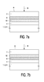
- a second transparent auxiliary layer I2 with reference numeral 12 having a refractive index n I2 and having a thickness d I2 in the range of 0 ⁇ d I2 ⁇ 3 ⁇ /8n I2 , is present adjacent the write-once L 0 recording layer 6 and d L0 is in the range of ⁇ /8n L0 ⁇ d L0 ⁇ 3 ⁇ /8n L0 or 5 ⁇ /8n L0 ⁇ d L0 ⁇ 7 ⁇ /8n L0 .
- d L0 is in the range of ⁇ /8n L0 ⁇ d L0 ⁇ 3 ⁇ /8n L0 or 5 ⁇ /8n L0 ⁇ d L0 ⁇ 7 ⁇ /8n L0 .
- the second transparent auxiliary layer 12 is present at a side of the write-once L 0 recording layer 6 most remote from the entrance face 8 and n I2 ⁇ n L0 /1.572.
- Fig.8a the maximum reflectivity of a recording layer/auxiliary layer stack is shown as a function of the refractive index n I of the auxiliary layer I for five values of the recording layer's refractive index n L0 is shown.
- the dashed line indicates the 18% value for R.
- Fig 8b the maximum reflectivity of an auxiliary layer/recording layer stack as a function of the refractive index n I of the auxiliary layer I for five values of the recording layer's refractive index n L0 is shown.
- the dashed line indicates the 18% value for R.
- Fig. 9 an embodiment of the L 0 stack of the dual-stack optical data storage medium 10 is shown as in Fig. 5 wherein additionally a first transparent auxiliary layer 13 (I1), having a refractive index n I1 ⁇ 1.8 and having a thickness d I1 ⁇ ⁇ /2n I1 , is present between the first metal reflective layer 11 and the transparent spacer layer 4.
- d I1 ⁇ ⁇ /4n I1 Preferably d I1 ⁇ ⁇ /4n I1 .
- the symbols have the meaning as described with Fig.2.
- the wavelength ⁇ of the focused laser beam 9 is 655nm.
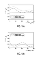
- the dashed line indicates the 50% value for T.
- Fig. 10b the reflection as a function of the recording layer thickness d L0 for the stacks of Fig.10a is shown.
- the dashed line indicates the 18% value for R.
- Fig.11 the maximum factor (X) by which the transmission of a recording layer/thin-metal reflective layer stack can be increased when adding an auxiliary I-layer adjacent the metal reflective layer as a function of the refractive index of the I-layer for three values of metal layer thickness.
- the dashed lines indicate linear approximations of the functions X(n I ) in the range 1.8 ⁇ n I ⁇ 3.0.
- L 0 stack it may be advantageous to apply a transparent heat sink in the L 0 recording stack instead of or in addition to the auxiliary layer(s). This may lead to improved recording performance due to heat sink action.
- auxiliary i.e. dielectric layer
- Typical dielectric materials used are ZnS-Si02 or SiO 2 , etc. These dielectric materials have poor heat conductivity, typically ⁇ 1 W/mK.
- An improved heat sink function can be obtained by replacing the dielectric with for instance ITO, HfN , or AION which have a heat conductivity > 1 W/mK (ITO has about 3.6 W/mK). These materials have optical constants close to typical dielectrics (n ⁇ 2, k ⁇ 0.05), therefore optical stack designs similar to those of e.g. Fig. 7 and Fig. 9 can be used.
- Fig.12 a schematic layout of an embodiment of the L 1 stack of the optical data storage medium 10 is shown. The symbols have the meaning as described with Fig.2.
- a second metal reflective layer 15 is present at a side of the write-once type L 1 recording layer 3 most remote from the entrance face 8.
- the second metal reflective layer 15 has a thickness d M1 ⁇ 25 nm and d L1 is in the range of 0 ⁇ d L1 ⁇ 3 ⁇ /4n L1 .
- a third transparent auxiliary layer 16 (I3) having a refractive index n I3 and having a thickness d I3 in the range 0 ⁇ d I3 ⁇ ⁇ /n I3 , is present adjacent the write-once type L 1 recording layer 3 at a side of the write-once type L 1 recording layer 3 closest to the entrance face 8.
- R L1 is the intrinsic reflection of the L 1 stack.
- the effective reflection as defined in annex D of the DVD read-only-disk book should be in the range 18% ⁇ R L1eff ⁇ 30%
- T L0 is the intrinsic transmission of the L 0 stack, i.e. for the lower lying L 1 stack having intrinsic reflection R L1 the effective reflection in a true dual-stack medium will be T L0 2 *R L1 .
- the wavelength ⁇ of the focused laser beam 9 is 655nm.
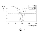
- a reflection R L1 0.73 is achieved.
- the dashed line indicates the 50% reflection level, which is a practical value for the L 1 intrinsic reflectivity.
- Fig.14 a schematic layout of an embodiment of the L 1 stack of the optical data storage medium 10 is shown. The symbols have the meaning as described with Fig.2.
- the second metal reflective layer 15 has a thickness d M1 ⁇ 25 nm.
- R L1 is the intrinsic reflection of the L 1 stack.
- the effective reflection as defined in annex D of the DVD read-only-disk book should be in the range 18% ⁇ R L1eff ⁇ 30%.
- T L0 is the intrinsic transmission of the L 0 stack, i.e. for the lower lying L 1 stack having intrinsic reflection R L1 the effective reflection in a true dual-stack medium will be T L0 2 *R L1 .
- the wavelength ⁇ of the focused laser beam 9 is 655nm.
- a fourth transparent auxiliary layer I4 having a refractive index n I4 and having a thickness d I4 in the range of 0 ⁇ d I4 ⁇ 3 ⁇ /16n I4 , may be present between the write-once L 1 recording layer and the second metal reflective layer 15.
- the wavelength ⁇ of the focused laser beam 9 is 655nm.
- the third metal reflective layer 17 is 10 nm Au.
- the fourth transparent auxiliary layer is 60 nm SiO 2 .
- a reflection R L1 0.63 is achieved.
- the dashed line indicates the 50% reflection level, which is a practical lower limit for the L 1 intrinsic reflectivity.
- a so-called type 1 medium is described.
- An optical recording stack (L 0 ), optically semi-transparent at the laser wavelength, is applied to a transparent, pre-grooved substrate 7.
- a transparent spacer layer 4 is attached to the L 0 stack.
- the spacer layer 4 either contains pregrooves (G) for L 1 or pregrooves (G) for L 1 are mastered into the spacer layer 4 after application to L 0 .
- Second recording stack L 1 is deposited on the grooved spacer layer 4. Finally, a counter substrate 1 is applied.
- a so-called type 2 medium is described.
- An optical recording stack (L 0 ), optically semi-transparent at the laser wavelength, is applied to a transparent, pre-grooved substrate 7.
- a second optical recording stack L 1 reflective at the laser wavelength, is applied to a second transparent pre-grooved (G) substrate 1.
- This substrate 1 with L 1 is attached to the substrate 7 with L 0 with a transparent spacer layer 4 in between.
- Preferred spacer-layer thickness for both disc types is 40 ⁇ m to 70 ⁇ m.
- the stacks proposed in this document are not restricted to use in DVD+R-DL and can be applied in any (multi-stack) organic-dye based optical recording medium.
- the thickness and optical constant ranges specified are such as to meet the requirements for an L 0 - and L 1 -stack of a DVD+R-DL medium.
- the actual recording of marks does not necessarily take place in the groove G but may take place in the area between grooves, also referred to as on-land.
- the guide groove G merely serves as a servo tracking means with the actual radiation beam recording spot being present on-land.
- a dual-stack optical data storage medium for write-once recording using a focused radiation beam entering through an entrance face of the medium.
- the medium comprises at least one substrate with present on a side thereof a first recording stack named L 0 , comprising a write-once type L 0 recording layer with an absorption k L0 and a second recording stack named L 1 comprising a write-once type L 1 recording layer with an absorption k L1 .
- the first recording stack L 0 has an optical reflection value R L0 and an optical transmission value T L0 and the second recording stack has an optical reflection value R L1 .
- the first recording stack is present at a position closer to the entrance face than the second recording stack.
Landscapes
- Optical Record Carriers And Manufacture Thereof (AREA)
- Optical Recording Or Reproduction (AREA)
- Signal Processing For Digital Recording And Reproducing (AREA)
- Holo Graphy (AREA)
- Manufacturing Optical Record Carriers (AREA)
- Thermal Transfer Or Thermal Recording In General (AREA)
Priority Applications (1)
| Application Number | Priority Date | Filing Date | Title |
|---|---|---|---|
| EP06114865A EP1742207A3 (de) | 2002-01-18 | 2003-01-16 | Optisches Datenspeichermedium für einmal beschreibbare Aufzeichnung |
Applications Claiming Priority (3)
| Application Number | Priority Date | Filing Date | Title |
|---|---|---|---|
| EP02075226 | 2002-01-18 | ||
| EP06114865A EP1742207A3 (de) | 2002-01-18 | 2003-01-16 | Optisches Datenspeichermedium für einmal beschreibbare Aufzeichnung |
| EP03700155A EP1472686B1 (de) | 2002-01-18 | 2003-01-16 | Optisches datenspeichermedium für aufzeichnen durch einmaliges beschreiben |
Related Parent Applications (1)
| Application Number | Title | Priority Date | Filing Date |
|---|---|---|---|
| EP03700155A Division EP1472686B1 (de) | 2002-01-18 | 2003-01-16 | Optisches datenspeichermedium für aufzeichnen durch einmaliges beschreiben |
Publications (2)
| Publication Number | Publication Date |
|---|---|
| EP1742207A2 true EP1742207A2 (de) | 2007-01-10 |
| EP1742207A3 EP1742207A3 (de) | 2007-04-25 |
Family
ID=8185552
Family Applications (2)
| Application Number | Title | Priority Date | Filing Date |
|---|---|---|---|
| EP03700155A Expired - Lifetime EP1472686B1 (de) | 2002-01-18 | 2003-01-16 | Optisches datenspeichermedium für aufzeichnen durch einmaliges beschreiben |
| EP06114865A Withdrawn EP1742207A3 (de) | 2002-01-18 | 2003-01-16 | Optisches Datenspeichermedium für einmal beschreibbare Aufzeichnung |
Family Applications Before (1)
| Application Number | Title | Priority Date | Filing Date |
|---|---|---|---|
| EP03700155A Expired - Lifetime EP1472686B1 (de) | 2002-01-18 | 2003-01-16 | Optisches datenspeichermedium für aufzeichnen durch einmaliges beschreiben |
Country Status (15)
| Country | Link |
|---|---|
| US (1) | US7573802B2 (de) |
| EP (2) | EP1472686B1 (de) |
| JP (2) | JP2005515582A (de) |
| KR (1) | KR100915664B1 (de) |
| CN (2) | CN100517477C (de) |
| AT (1) | ATE329349T1 (de) |
| AU (1) | AU2003201462A1 (de) |
| CY (1) | CY1105258T1 (de) |
| DE (1) | DE60305879T2 (de) |
| DK (1) | DK1472686T3 (de) |
| ES (1) | ES2263947T3 (de) |
| PT (1) | PT1472686E (de) |
| SI (1) | SI1472686T1 (de) |
| TW (1) | TWI286749B (de) |
| WO (1) | WO2003060895A1 (de) |
Families Citing this family (9)
| Publication number | Priority date | Publication date | Assignee | Title |
|---|---|---|---|---|
| ATE343838T1 (de) * | 2002-04-02 | 2006-11-15 | Koninkl Philips Electronics Nv | Doppelschichtiges optisches datenaufzeichnungsmedium |
| CN100385538C (zh) * | 2002-12-13 | 2008-04-30 | 皇家飞利浦电子股份有限公司 | 双叠层光学数据存储介质 |
| CA2530896A1 (en) | 2003-07-01 | 2005-01-13 | Koninklijke Philips Electronics N.V. | Method of recording information on a multi layer record carrier, and device for recording on a dual layer record carrier |
| CA2530890A1 (en) * | 2003-07-03 | 2005-01-13 | Koninklijke Philips Electronics N.V. | Multi stack optical data storage medium and use of such medium |
| EP1647013B1 (de) * | 2003-07-11 | 2012-05-23 | Koninklijke Philips Electronics N.V. | Beschreibbarer optischer datenträger |
| WO2005101394A1 (ja) * | 2004-04-13 | 2005-10-27 | Ricoh Company, Ltd. | 2層型光記録媒体及びその記録再生方法、並びに光記録再生装置 |
| JP4412101B2 (ja) | 2004-08-03 | 2010-02-10 | Tdk株式会社 | 光記録媒体 |
| EP1810291B1 (de) * | 2004-11-10 | 2012-09-05 | Ricoh Company, Ltd. | Optisches aufzeichnungsmedium, aufzeichnungs- und wiedergabeverfahren dafür und vorrichtung zur optischen aufzeichnung und wiedergabe |
| BRPI0619406B1 (pt) * | 2005-12-06 | 2019-01-02 | Koninklijke Philips Nv | dispositivo para gravar informações sobre um suporte de gravação, método de formatar um suporte de gravação para gravar dados e recuperar dados |
Family Cites Families (18)
| Publication number | Priority date | Publication date | Assignee | Title |
|---|---|---|---|---|
| JP2647982B2 (ja) * | 1989-12-11 | 1997-08-27 | 日本電気株式会社 | 光記憶体 |
| JPH04321946A (ja) * | 1991-04-22 | 1992-11-11 | Hitachi Chem Co Ltd | 光記録媒体 |
| JPH05101443A (ja) * | 1991-10-01 | 1993-04-23 | Kao Corp | 光記録媒体 |
| US5764619A (en) * | 1995-04-07 | 1998-06-09 | Matsushita Electric Industrial Co., Ltd. | Optical recording medium having two separate recording layers |
| US5627817A (en) * | 1995-05-08 | 1997-05-06 | International Business Machines Corporation | Optical disk data storage system with multiple write-once dye-based data layers |
| US5669995A (en) * | 1996-01-29 | 1997-09-23 | Hong; Gilbert H. | Method for writing and reading data on a multi-layer recordable interferometric optical disc and method for fabricating such |
| JPH10235997A (ja) * | 1997-02-26 | 1998-09-08 | Toshiba Corp | 相変化光記録媒体 |
| JPH1166622A (ja) | 1997-08-25 | 1999-03-09 | Taiyo Yuden Co Ltd | 光情報媒体とその記録再生方法 |
| TW473712B (en) * | 1998-05-12 | 2002-01-21 | Koninkl Philips Electronics Nv | Rewritable double layer optical information medium |
| US6511788B1 (en) * | 1999-02-12 | 2003-01-28 | Sony Corporation | Multi-layered optical disc |
| JP2000285511A (ja) * | 1999-03-30 | 2000-10-13 | Toshiba Corp | 光記録媒体 |
| JP2000311384A (ja) * | 1999-04-26 | 2000-11-07 | Fuji Photo Film Co Ltd | 光情報記録媒体 |
| JP2000353338A (ja) * | 1999-06-10 | 2000-12-19 | Sony Corp | 光ディスク及び光ディスク再生装置 |
| US6469977B2 (en) * | 1999-12-20 | 2002-10-22 | Matsushita Electric Industrial Co., Ltd. | Optical information recording medium, method for producing the same, and method and apparatus for recording/reproducing information thereon |
| TW575875B (en) * | 2002-04-02 | 2004-02-11 | Ind Tech Res Inst | Multi-layered film rewritable information storage medium |
| AU2003272009A1 (en) * | 2002-11-06 | 2004-06-07 | Koninklijke Philips Electronics N.V. | Multi-stack optical data storage medium and use of such medium |
| JP2006528818A (ja) * | 2003-07-25 | 2006-12-21 | コーニンクレッカ フィリップス エレクトロニクス エヌ ヴィ | ハイブリッド追記型光学式記録担体 |
| WO2005036536A2 (en) * | 2003-10-09 | 2005-04-21 | Koninklijke Philips Electronics N.V. | Dual-stack optical data storage medium for write once recording |
-
2003
- 2003-01-16 AU AU2003201462A patent/AU2003201462A1/en not_active Abandoned
- 2003-01-16 PT PT03700155T patent/PT1472686E/pt unknown
- 2003-01-16 KR KR1020047010987A patent/KR100915664B1/ko not_active Expired - Fee Related
- 2003-01-16 CN CNB038023407A patent/CN100517477C/zh not_active Expired - Fee Related
- 2003-01-16 EP EP03700155A patent/EP1472686B1/de not_active Expired - Lifetime
- 2003-01-16 AT AT03700155T patent/ATE329349T1/de active
- 2003-01-16 DE DE60305879T patent/DE60305879T2/de not_active Expired - Lifetime
- 2003-01-16 JP JP2003560910A patent/JP2005515582A/ja active Pending
- 2003-01-16 CN CN2007101026831A patent/CN101055738B/zh not_active Expired - Fee Related
- 2003-01-16 SI SI200330433T patent/SI1472686T1/sl unknown
- 2003-01-16 DK DK03700155T patent/DK1472686T3/da active
- 2003-01-16 WO PCT/IB2003/000090 patent/WO2003060895A1/en not_active Ceased
- 2003-01-16 EP EP06114865A patent/EP1742207A3/de not_active Withdrawn
- 2003-01-16 US US10/501,429 patent/US7573802B2/en not_active Expired - Fee Related
- 2003-01-16 ES ES03700155T patent/ES2263947T3/es not_active Expired - Lifetime
- 2003-01-20 TW TW092101110A patent/TWI286749B/zh not_active IP Right Cessation
-
2006
- 2006-09-06 CY CY20061101269T patent/CY1105258T1/el unknown
-
2007
- 2007-11-29 JP JP2007309400A patent/JP2008097820A/ja active Pending
Also Published As
| Publication number | Publication date |
|---|---|
| CN101055738B (zh) | 2011-04-06 |
| PT1472686E (pt) | 2006-10-31 |
| US7573802B2 (en) | 2009-08-11 |
| DE60305879T2 (de) | 2007-03-01 |
| JP2008097820A (ja) | 2008-04-24 |
| ES2263947T3 (es) | 2006-12-16 |
| HK1070737A1 (en) | 2005-06-24 |
| EP1472686A1 (de) | 2004-11-03 |
| WO2003060895A1 (en) | 2003-07-24 |
| CY1105258T1 (el) | 2010-03-03 |
| US20050042545A1 (en) | 2005-02-24 |
| ATE329349T1 (de) | 2006-06-15 |
| TW200302470A (en) | 2003-08-01 |
| EP1472686B1 (de) | 2006-06-07 |
| CN1618097A (zh) | 2005-05-18 |
| EP1742207A3 (de) | 2007-04-25 |
| KR100915664B1 (ko) | 2009-09-04 |
| KR20040075936A (ko) | 2004-08-30 |
| SI1472686T1 (sl) | 2006-12-31 |
| DE60305879D1 (de) | 2006-07-20 |
| CN100517477C (zh) | 2009-07-22 |
| CN101055738A (zh) | 2007-10-17 |
| JP2005515582A (ja) | 2005-05-26 |
| DK1472686T3 (da) | 2006-10-16 |
| TWI286749B (en) | 2007-09-11 |
| AU2003201462A1 (en) | 2003-07-30 |
Similar Documents
| Publication | Publication Date | Title |
|---|---|---|
| US7221642B2 (en) | Optical data storage medium and use of such medium | |
| EP1570466B1 (de) | Optisches mehrstapel-datenspeichermedium und verwendung eines solchen mediums | |
| JP2008097820A (ja) | 追記形記録用の光データ記憶媒体 | |
| EP1518229B1 (de) | Optisches speichermedium | |
| KR100342640B1 (ko) | 광학적 정보 기록 매체 및 광학적 정보 기록 매체 상의정보를 기록, 재생, 및 소거하는 방법 | |
| EP1573727B1 (de) | Doppelschichtiges optisches aufzeichnungsmedium und der gebrauch eines solchen mediums | |
| EP1673769B1 (de) | Optisches doppelstapel-datenspeichermedium zur einmalbeschreibbaren aufzeichnung | |
| JP4252482B2 (ja) | 読み出し専用型多層型光情報記録媒体及びその製造方法 | |
| EP1652177A1 (de) | Hybrider beschreibbarer optischer datenträger | |
| HK1070737B (en) | Optical data storage medium for write once recording | |
| US20050163023A1 (en) | Optical data storage medium | |
| HK1091939B (en) | Dual-stack optical data storage medium for write once recording |
Legal Events
| Date | Code | Title | Description |
|---|---|---|---|
| PUAI | Public reference made under article 153(3) epc to a published international application that has entered the european phase |
Free format text: ORIGINAL CODE: 0009012 |
|
| AC | Divisional application: reference to earlier application |
Ref document number: 1472686 Country of ref document: EP Kind code of ref document: P |
|
| AK | Designated contracting states |
Kind code of ref document: A2 Designated state(s): AT BE BG CH CY CZ DE DK EE ES FI FR GB GR HU IE IS IT LI LT LU LV MC NL PL PT RO SE SI SK TR |
|
| PUAL | Search report despatched |
Free format text: ORIGINAL CODE: 0009013 |
|
| AK | Designated contracting states |
Kind code of ref document: A3 Designated state(s): AT BE BG CH CY CZ DE DK EE ES FI FR GB GR HU IE IS IT LI LT LU LV MC NL PL PT RO SE SI SK TR |
|
| 17P | Request for examination filed |
Effective date: 20071025 |
|
| AKX | Designation fees paid |
Designated state(s): AT BE BG CH CY CZ DE DK EE ES FI FR GB GR HU IE IT LI LU MC NL PT SE SI SK TR |
|
| 17Q | First examination report despatched |
Effective date: 20071213 |
|
| STAA | Information on the status of an ep patent application or granted ep patent |
Free format text: STATUS: THE APPLICATION IS DEEMED TO BE WITHDRAWN |
|
| 18D | Application deemed to be withdrawn |
Effective date: 20080624 |