EP1742262B1 - Dissipateur de chaleur amovible - Google Patents
Dissipateur de chaleur amovible Download PDFInfo
- Publication number
- EP1742262B1 EP1742262B1 EP06101143A EP06101143A EP1742262B1 EP 1742262 B1 EP1742262 B1 EP 1742262B1 EP 06101143 A EP06101143 A EP 06101143A EP 06101143 A EP06101143 A EP 06101143A EP 1742262 B1 EP1742262 B1 EP 1742262B1
- Authority
- EP
- European Patent Office
- Prior art keywords
- heat dissipation
- extendable
- base
- extendable heat
- dissipation apparatus
- Prior art date
- Legal status (The legal status is an assumption and is not a legal conclusion. Google has not performed a legal analysis and makes no representation as to the accuracy of the status listed.)
- Expired - Lifetime
Links
Images




Classifications
-
- H—ELECTRICITY
- H10—SEMICONDUCTOR DEVICES; ELECTRIC SOLID-STATE DEVICES NOT OTHERWISE PROVIDED FOR
- H10W—GENERIC PACKAGES, INTERCONNECTIONS, CONNECTORS OR OTHER CONSTRUCTIONAL DETAILS OF DEVICES COVERED BY CLASS H10
- H10W40/00—Arrangements for thermal protection or thermal control
- H10W40/70—Fillings or auxiliary members in containers or in encapsulations for thermal protection or control
- H10W40/73—Fillings or auxiliary members in containers or in encapsulations for thermal protection or control for cooling by change of state
-
- H—ELECTRICITY
- H10—SEMICONDUCTOR DEVICES; ELECTRIC SOLID-STATE DEVICES NOT OTHERWISE PROVIDED FOR
- H10W—GENERIC PACKAGES, INTERCONNECTIONS, CONNECTORS OR OTHER CONSTRUCTIONAL DETAILS OF DEVICES COVERED BY CLASS H10
- H10W40/00—Arrangements for thermal protection or thermal control
- H10W40/20—Arrangements for cooling
- H10W40/22—Arrangements for cooling characterised by their shape, e.g. having conical or cylindrical projections
-
- H—ELECTRICITY
- H10—SEMICONDUCTOR DEVICES; ELECTRIC SOLID-STATE DEVICES NOT OTHERWISE PROVIDED FOR
- H10W—GENERIC PACKAGES, INTERCONNECTIONS, CONNECTORS OR OTHER CONSTRUCTIONAL DETAILS OF DEVICES COVERED BY CLASS H10
- H10W40/00—Arrangements for thermal protection or thermal control
- H10W40/40—Arrangements for thermal protection or thermal control involving heat exchange by flowing fluids
- H10W40/43—Arrangements for thermal protection or thermal control involving heat exchange by flowing fluids by flowing gases, e.g. forced air cooling
-
- F—MECHANICAL ENGINEERING; LIGHTING; HEATING; WEAPONS; BLASTING
- F28—HEAT EXCHANGE IN GENERAL
- F28F—DETAILS OF HEAT-EXCHANGE AND HEAT-TRANSFER APPARATUS, OF GENERAL APPLICATION
- F28F2215/00—Fins
Definitions
- the present invention relates to a heat dissipation apparatus. More particularly, the present invention relates to a heat dissipation apparatus which can extend to increase heat dissipation area.
- a conventional heat dissipation technique is to attach a heat dissipation apparatus 100 to an electrical device such as a chip, as shown in Fig. 1 , and even to mount a fan on the heat dissipation apparatus 100.
- a heat pipe may also be used to improve heat transfer efficiency.
- WO 01/041520 A1 describes a U-shaped heat sink assembly formed by injection molding of a thermally conductive polymer composite material, including a base member with a number of hinged integrated fin members thereon.
- US 6 330 157 B1 describes a variable thermal exchanger including a base and fins perpendicular to the base, the fins defining a plurality of cooling fluid channels.
- US 5 781 409 A describes a heat dissipating lid hinge structure with laterally offset heat pipe end portions.
- an extendable heat dissipation apparatus for adjusting heat dissipation area having the technical features described in the independent claims. Preferred embodiments of the present invention are described in the dependent claims.
- the extendable heat dissipation apparatus includes a base, an extendable heat dissipation member and a connecting element.
- the connecting element is coupled between the base and the extendable heat dissipation member.
- the extendable heat dissipation member is integrated in the heat dissipation apparatus through the connecting element and extends to an extending location with respect to the base.
- an extendable heat dissipation apparatus is applied in a computer system and installed on an add-in card near a north bridge chip.
- the extension of the extendable heat dissipation member to the space above the north bridge chip or a CPU not only leads to a larger heat dissipation area, but obtains an advantageous convection by airflow from a CPU fan in the space; therefore heat dissipation efficiency is improved.
- the extendable heat dissipation apparatus of the invention is applicable to various dimensions of electrical systems such as computer systems and is able to adjust heat dissipation area of the heat dissipation apparatus so that spare space within the system can be utilized fully.
- a CPU fan when space above a north bridge chip is used for extension of the heat dissipation apparatus, a CPU fan also provides a heat convection for the apparatus to obtain a better heat dissipation effect.
- the present invention provides users with an adjusting mechanism through an extendable heat dissipation member, such that the heat dissipation apparatus can be expanded to achieve a larger heat dissipation area and a better heat dissipation efficiency according to a system volume, thus fully utilizing spare space in the system to improve heat dissipation, especially for systems with enough sufficiently large space.
- Figs. 2A and 2B are respectively an oblique view and a side view of an extendable heat dissipation apparatus in accordance with a preferred embodiment of the present invention.
- the extendable heat dissipation apparatus 250 includes a base 210, an extendable heat dissipation member 230, and a connecting element 240.
- the connecting element 240 is coupled with the base 210 and the extendable heat dissipation member 230, and the extendable heat dissipation member 230 extends to an extended location away from the base 210.
- a plurality of normal fins 220 are fixed on the base 210, and a circuit board 290 has chips 292 and 294 on both sides.
- a combination of the circuit board and the chip may be a computer motherboard with a south bridge chip, a north bridge chip or other functional chips; the combination may also be an add-in card board with chips, such as a graphics card with image processing chips.
- the extendable heat dissipation apparatus 250 is attached on the side of the chip 294 on the circuit board 290, and a plurality of first normal fins 220 are fixed on a first base 210.
- a connecting element 240 such as a pivoting mechanism, is disposed on the first base 210 and makes a structural connection between an extendable heat dissipation member 230 and the first base 210.
- the extendable heat dissipation member 230 includes a body 232 and a plurality of extending fins 234 thereon.
- the extending fins 234 are arranged such that when the extendable heat dissipation member 230 is rotated towards the first base 210 to be stored, as along an arrow 280, each of the extending fins 234 is inserted correspondingly in a first fin gap 222 defined by the first normal fins 220, and each of the first normal fins 220 is inserted in an extending fin gap 236 likewise defined by the extending fins 234.
- the apparatus can be either folded so that fins are intermeshed (but not in contact with each other), or unfolded so that extending fins are fully exposed.
- the connecting element 240 enable extending and storing of the extendable heat dissipation member 230 with respect to the base 210; therefore, the apparatus provides dimensional flexibility.
- a second heat dissipation apparatus 270 is further attached on the side of the chip 292 on the circuit board 290, wherein a typical heat dissipation apparatus is used in the embodiment. Alternatively, another extendable heat dissipation apparatus may be used.
- the second heat dissipation apparatus 270 includes a second base 252 attached to the chip 292 and a plurality of second normal fins 254 formed or set on the second base 252.
- a heat pipe 260 is connected between the second heat dissipation apparatus 270 and the extending heat dissipation apparatus 250.
- a U-shaped heat pipe is used and is connected to the extendable heat dissipation member 230 of the extendable heat dissipation apparatus 250, whereby heat from the second heat dissipation apparatus 270 is transferred more efficiently to the extendable heat dissipation apparatus 250 and fully utilizes the extendable heat dissipation member 230 to dissipate heat.
- the heat pipe 260 can also be connected between the first base 210 and the extendable heat dissipation member 230 to improve the heat dissipation efficiency of the apparatus itself.
- fins are not limited to the structure and shape described in the embodiment.
- Figs. 3A and 3B illustrate an oblique view and a side view of the extendable heat dissipation apparatus in accordance with another preferred embodiment of the present invention.
- chips 392 and 394 disposed on both sides of a circuit board 390 are attached to a first extendable heat dissipation apparatus 350a and a second extendable heat dissipation apparatus 350b, respectively.
- the extendable heat dissipation apparatus 350a includes a base 310, a plurality of normal fins 320 formed or set on the base 310, and an extendable heat dissipation member 330 coupled to the base through a connecting element 340.
- the connecting element 340 is a flat spring and the extendable heat dissipation member 330 is formed as a plurality of spread fins 334.
- the flat spring set in a fin gap 322 defined by the normal fins 320 is coupled to and constrainedly accommodates the corresponding spread fin 334 in the fin gap 322.
- the flat spring allows the spread fin 334 to contact the base 310 and the normal fins 320 closely and tightly, promoting distribution of heat to the spread fin 334 so that heat dissipation area of the spread fins 334 can be utilized.
- the extendable heat dissipation member 330 can be stored in a storing location, that is in the fin gap 322. In a large and wide system, a portion of the extendable heat dissipation member 330 can be rotated to depart from constraint by the flat spring to spread to an extended location so that available space is effectively used. Further, a heat pipe 360 is used to connect the extendable heat dissipation apparatuses 350a and 350b for improving heat transfer.
- a spread angle of the extendable heat dissipation member 330 is determined by the flat spring, wherein a sequential arrangement of spread angles with different degrees is preferable, such as an arrangement of increasing angles for reducing overlapping areas between the spread fins 334, in order to reduce heat dissipation efficiency loss.
- the spread fins 334 may include a forked end 336 in consideration of an optimal heat dissipation area, but the number of the forked ends is not limited to what is shown in the embodiment.
- Some or all of the base, fins and the connecting element are made of a metal with high heat transfer coefficient such as copper or aluminum.
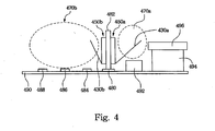
- Fig. 4 illustrates a schematic diagram of the extendable heat dissipation apparatus applied in a computer system.
- the heat dissipation apparatus of the present invention can be applied to various motherboard specifications, which often correspond to computer cases of different dimensions.
- the extendable heat dissipation apparatus is adjustable to meet a specific case dimension.
- a CPU 494, a north bridge chip 492, an adjacent expansion slot 480, and a plurality of expansion slots 484 - 488 is set on a motherboard 490.
- the specification of the motherboard may be ATX or Baby AT, and the expansion slots may be AGP, PCI or a PCI Express bus interface.
- a fan 496 is installed on the CPU 494 for cooling.
- An add-in card 482 is inserted in the adjacent expansion slot 480, which is adjacent to the north bridge chip 492; and a first extendable heat dissipation apparatus 450a and a second extendable heat dissipation apparatus 450b are installed on both sides of the add-in card 482.
- the extendable heat dissipation apparatuses 450a and 450b can extend respectively into a first space 470a above the north bridge chip 492 and a second space 470b above the expansion slots 484 - 488 with individual extendable heat dissipation members.
- the heat dissipation area of the first extendable heat dissipation apparatus 450a is increased by spreading the first extendable heat dissipation member 430a into the first space 470a, and airflow from the fan 496 on the CPU 494 also provides convection of the extendable heat dissipation apparatus 450a.
- the second extendable heat dissipation member 430b of the second extendable heat dissipation apparatus 450b is further spread into the second space 470b, achieving a larger heat dissipation area.
- the extent to which the extendable heat dissipation member extends depends on the motherboard configuration and is not limited to the space above the north bridge chip in the embodiment; for example, the space above the CPU may also be an extended space in a different specification motherboard. Each space can effectively utilize the airflow provided by the CPU fan to improve heat dissipation efficiency.
- a connecting element 540 includes an engaging part 540a and an engaging groove member 540b.
- the engaging part is coupled with a base 510, and the engaging groove member is connected with an extendable heat dissipation member 530.
- the engaging part 540a is engaged with the engaging groove member 540b, which structurally connects the extendable heat dissipation member 530 with the base 510.
- Larger contacting area and tighter contact between the extendable heat dissipation member 530 and the base 510 makes better heat transfer effect. Therefore, the extendable heat dissipation member 530 shares the burden of heat dissipation by way of expanding heat dissipation area within an extra available space.
- Combination of the engaging part 540a and the engaging groove member 540b is not limited to the embodiment; for example, arrangement of the engaging part 540a and the engaging groove member 540b is interchangeable, shapes and outlines of which are not limited therein. Any connecting element that connects the extendable heat dissipation member 530 with the base 510 is included in the present invention.
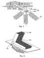
- Fig. 6 shows an oblique view of an extendable heat dissipation apparatus in accordance with another preferred embodiment of the present invention, in which an extendable heat dissipation member 630 is connected to the base 610 at a predetermined angle 602 that determines space occupied by the extendable heat dissipation member 630.
- the angle is designed to comply with a practical environment; for example, it may be L-shaped and about 90 degrees.
- a connecting element is a heat pipe 742.
- the heat pipe 742 is coupled to a base 710 with an end and extends out of the base 710 with another end.
- a bend 702 is formed between two ends, such as a 90-degree bend.
- An extendable heat dissipation member 730 is coupled with the extending end of the heat pipe 742.
- Fig. 7B is an oblique view of another aspect of the extendable heat dissipation apparatus in Fig. 7A .
- the heat pipe 742 is coupled with the extendable heat dissipation member 730 and the base 710, and the extendable heat dissipation member 730 is firmly supported by a bracket 750.
- the extending orientation of the extendable heat dissipation member 730 can be changed by the heat pipe 742.
- the present invention has at least the following advantage.
- the extendable heat dissipation apparatus integrates an extendable heat dissipation member and provides modes of storing and extending.
- the extending mode presents various forms corresponding to different system dimensions, and a wider extending range makes larger heat dissipation area and better heat dissipation efficiency. Therefore, the present invention effectively utilizes available space in a system and achieves a better heat dissipation efficiency.
- the extendable heat dissipation apparatus makes use of space above unused expansion slots for increasing extra heat dissipation area, and space above the north bridge chip along with the CPU fan for providing improved convection of the extendable heat dissipation member, which significantly helps the operational stability of the computer.
Landscapes
- Cooling Or The Like Of Electrical Apparatus (AREA)
- Cooling Or The Like Of Semiconductors Or Solid State Devices (AREA)
Claims (8)
- Appareil de dissipation de la chaleur (250) extensible, comprenant :une base (210) ;une pluralité d'ailettes (220) normales disposées sur la base (210) ;un élément de raccordement (240) couplé à la base (210) ; etun élément de dissipation de la chaleur (230) extensible couplé à l'élément de raccordement (240) et extensible à un emplacement étendu par rapport à la base (210), dans lequel l'élément de dissipation de la chaleur (230) extensible comprend un corps (232) et une pluralité d'ailettes (234) qui s'étendent sur le corps (232), les ailettes (234) qui s'étendent sont insérées dans des interstices d'ailettes (222) entre les ailettes normales (220) lorsque l'élément de dissipation de la chaleur (230) extensible est stocké dans un emplacement de stockage par rapport à la base (210) dans un mode de stockage, et les ailettes (234) qui s'étendent sortent des interstices d'ailettes (222) entre les ailettes normales (220) lorsque l'élément de dissipation de la chaleur (230) extensible est étendu vers l'emplacement étendu.
- Appareil de dissipation de la chaleur (250) extensible selon la revendication 1, dans lequel l'élément de raccordement (240) est un ressort plat.
- Appareil de dissipation de la chaleur (250) extensible selon la revendication 1, dans lequel l'élément de raccordement (240) est un mécanisme pivotant.
- Appareil de dissipation de la chaleur (250) extensible selon la revendication 1, dans lequel l'élément de raccordement (240) comprend une partie de mise en prise couplée à la base (210) et un élément de rainure de mise en prise couplé à l'élément de dissipation de la chaleur (230) extensible et est mis en prise avec la partie de mise en prise.
- Appareil de dissipation de la chaleur (250) extensible selon la revendication 1, dans lequel l'élément de dissipation de la chaleur (230) extensible est raccordé à la base (210) sous un angle prédéterminé.
- Appareil de dissipation de la chaleur (250) extensible selon la revendication 1, comprenant en outre un caloduc dont les deux extrémités sont couplées respectivement à l'élément de dissipation de la chaleur (230) extensible et à la base (210).
- Appareil de dissipation de la chaleur (250) extensible selon la revendication 1, dans lequel l'élément de raccordement (240) est un caloduc dont les deux extrémités sont couplées respectivement à l'élément de dissipation de la chaleur (230) extensible et à la base (210).
- Appareil de dissipation de la chaleur (250) extensible selon la revendication 1, dans lequel l'élément de dissipation de la chaleur (230) extensible s'étend au-dessus d'une puce Northbridge ou d'une CPU.
Applications Claiming Priority (1)
| Application Number | Priority Date | Filing Date | Title |
|---|---|---|---|
| CNB2005100828107A CN100361045C (zh) | 2005-07-08 | 2005-07-08 | 伸展式散热装置 |
Publications (3)
| Publication Number | Publication Date |
|---|---|
| EP1742262A2 EP1742262A2 (fr) | 2007-01-10 |
| EP1742262A3 EP1742262A3 (fr) | 2008-07-30 |
| EP1742262B1 true EP1742262B1 (fr) | 2010-12-29 |
Family
ID=37026988
Family Applications (1)
| Application Number | Title | Priority Date | Filing Date |
|---|---|---|---|
| EP06101143A Expired - Lifetime EP1742262B1 (fr) | 2005-07-08 | 2006-02-01 | Dissipateur de chaleur amovible |
Country Status (3)
| Country | Link |
|---|---|
| EP (1) | EP1742262B1 (fr) |
| CN (1) | CN100361045C (fr) |
| DE (1) | DE602006019177D1 (fr) |
Families Citing this family (7)
| Publication number | Priority date | Publication date | Assignee | Title |
|---|---|---|---|---|
| TWI348885B (en) * | 2007-11-30 | 2011-09-11 | Ama Precision Inc | Heat dissipation module |
| CN101636063B (zh) * | 2008-07-25 | 2012-06-27 | 微盟电子(昆山)有限公司 | 导风结构 |
| CN102410514B (zh) * | 2010-09-21 | 2015-11-25 | 欧司朗股份有限公司 | 散热结构和具有该散热结构的射灯 |
| GB2500678B (en) * | 2012-03-29 | 2016-01-06 | Spirax Sarco Ltd | A Thermoelectric generator and a thermoelectric power source |
| CN104582451A (zh) * | 2015-01-30 | 2015-04-29 | 胡俊 | 一种散热模组 |
| US10779439B2 (en) * | 2018-05-24 | 2020-09-15 | Quanta Computer Inc. | Remote heat exchanger |
| CN110285362B (zh) * | 2019-08-12 | 2021-11-02 | 中山市冠华照明灯饰有限公司 | 一种led筒灯 |
Family Cites Families (11)
| Publication number | Priority date | Publication date | Assignee | Title |
|---|---|---|---|---|
| US5339214A (en) * | 1993-02-12 | 1994-08-16 | Intel Corporation | Multiple-fan microprocessor cooling through a finned heat pipe |
| US5574626A (en) * | 1995-07-12 | 1996-11-12 | Unisys Corporation | Add-on heat sink |
| US5781409A (en) | 1996-12-19 | 1998-07-14 | Compaq Computer Corporation | Heat dissipating lid hinge structure with laterally offset heat pipe end portions |
| US6016250A (en) * | 1998-01-30 | 2000-01-18 | Credence Systems Corporation | Self-balancing thermal control device for integrated circuits |
| KR19980019402A (ko) * | 1998-03-16 | 1998-06-05 | 천기완 | 피.씨의 씨.피.유 냉각장치(cpu cooling device of pc) |
| TW556074B (en) * | 1998-12-15 | 2003-10-01 | Foxconn Prec Components Co Ltd | Heat sink and the manufacturing method thereof |
| US6234240B1 (en) * | 1999-07-01 | 2001-05-22 | Kioan Cheon | Fanless cooling system for computer |
| US6385047B1 (en) | 1999-12-06 | 2002-05-07 | Cool Shield, Inc. | U-shaped heat sink assembly |
| US6330157B1 (en) | 1999-12-21 | 2001-12-11 | International Business Machines Corporation | Variable thermal exchanger and method thereof |
| CN2465235Y (zh) * | 2001-02-20 | 2001-12-12 | 神达电脑股份有限公司 | 芯片组散热片组件 |
| US6832410B2 (en) * | 2002-04-23 | 2004-12-21 | Hewlett-Packard Development Company, L.P. | High performance cooling device with side mount fan |
-
2005
- 2005-07-08 CN CNB2005100828107A patent/CN100361045C/zh not_active Expired - Lifetime
-
2006
- 2006-02-01 DE DE602006019177T patent/DE602006019177D1/de not_active Expired - Lifetime
- 2006-02-01 EP EP06101143A patent/EP1742262B1/fr not_active Expired - Lifetime
Also Published As
| Publication number | Publication date |
|---|---|
| CN1851610A (zh) | 2006-10-25 |
| CN100361045C (zh) | 2008-01-09 |
| DE602006019177D1 (de) | 2011-02-10 |
| EP1742262A2 (fr) | 2007-01-10 |
| EP1742262A3 (fr) | 2008-07-30 |
Similar Documents
| Publication | Publication Date | Title |
|---|---|---|
| US7411791B2 (en) | Extendable heat dissipation apparatus | |
| US7474527B2 (en) | Desktop personal computer and thermal module thereof | |
| US6795315B1 (en) | Cooling system | |
| US7051791B2 (en) | Cooling apparatus and electronic equipment | |
| CN103688351B (zh) | 紧凑型散热模组 | |
| US7564686B2 (en) | Heat-dissipating module | |
| US20050099774A1 (en) | Semiconductor chip cooling module with fin-fan-fin configuration | |
| US20070000643A1 (en) | Heat sink | |
| TWI399165B (zh) | 用以有效冷卻一處理器的系統 | |
| US20070097654A1 (en) | Heat dissipation device | |
| JP2004295718A (ja) | 情報処理装置の液例システム | |
| US7688590B2 (en) | Thermal module and electronic apparatus using the same | |
| WO2004084600A1 (fr) | Module a semi-conducteurs et dispositif de refroidissement | |
| US20090034196A1 (en) | Heat-dissipating module | |
| US7385820B1 (en) | Heat dissipation module | |
| EP1742262B1 (fr) | Dissipateur de chaleur amovible | |
| CN111031767B (zh) | 电子设备以及散热模组 | |
| JP2007172076A (ja) | 放熱装置およびそれを用いた電子機器 | |
| US20040159935A1 (en) | Thermally optimized conductive block | |
| US20090034193A1 (en) | Heat-dissipating module | |
| CN101365318A (zh) | 散热组件 | |
| KR100521330B1 (ko) | 컴퓨터 시스템의 방열 구조 | |
| CN101365319A (zh) | 散热组件 | |
| JP3100594U (ja) | 一体型熱放散装置 | |
| CN101365320A (zh) | 散热组件 |
Legal Events
| Date | Code | Title | Description |
|---|---|---|---|
| PUAI | Public reference made under article 153(3) epc to a published international application that has entered the european phase |
Free format text: ORIGINAL CODE: 0009012 |
|
| AK | Designated contracting states |
Kind code of ref document: A2 Designated state(s): AT BE BG CH CY CZ DE DK EE ES FI FR GB GR HU IE IS IT LI LT LU LV MC NL PL PT RO SE SI SK TR |
|
| AX | Request for extension of the european patent |
Extension state: AL BA HR MK YU |
|
| PUAL | Search report despatched |
Free format text: ORIGINAL CODE: 0009013 |
|
| AK | Designated contracting states |
Kind code of ref document: A3 Designated state(s): AT BE BG CH CY CZ DE DK EE ES FI FR GB GR HU IE IS IT LI LT LU LV MC NL PL PT RO SE SI SK TR |
|
| AX | Request for extension of the european patent |
Extension state: AL BA HR MK YU |
|
| 17P | Request for examination filed |
Effective date: 20090113 |
|
| AKX | Designation fees paid |
Designated state(s): DE FR GB |
|
| RTI1 | Title (correction) |
Free format text: HINGED HEAT DISSIPATION APPARATUS |
|
| GRAP | Despatch of communication of intention to grant a patent |
Free format text: ORIGINAL CODE: EPIDOSNIGR1 |
|
| GRAS | Grant fee paid |
Free format text: ORIGINAL CODE: EPIDOSNIGR3 |
|
| GRAA | (expected) grant |
Free format text: ORIGINAL CODE: 0009210 |
|
| AK | Designated contracting states |
Kind code of ref document: B1 Designated state(s): DE FR GB |
|
| REG | Reference to a national code |
Ref country code: GB Ref legal event code: FG4D |
|
| REF | Corresponds to: |
Ref document number: 602006019177 Country of ref document: DE Date of ref document: 20110210 Kind code of ref document: P |
|
| REG | Reference to a national code |
Ref country code: DE Ref legal event code: R096 Ref document number: 602006019177 Country of ref document: DE Effective date: 20110210 |
|
| PLBE | No opposition filed within time limit |
Free format text: ORIGINAL CODE: 0009261 |
|
| STAA | Information on the status of an ep patent application or granted ep patent |
Free format text: STATUS: NO OPPOSITION FILED WITHIN TIME LIMIT |
|
| 26N | No opposition filed |
Effective date: 20110930 |
|
| REG | Reference to a national code |
Ref country code: DE Ref legal event code: R097 Ref document number: 602006019177 Country of ref document: DE Effective date: 20110930 |
|
| REG | Reference to a national code |
Ref country code: FR Ref legal event code: PLFP Year of fee payment: 11 |
|
| REG | Reference to a national code |
Ref country code: FR Ref legal event code: PLFP Year of fee payment: 12 |
|
| REG | Reference to a national code |
Ref country code: FR Ref legal event code: PLFP Year of fee payment: 13 |
|
| P01 | Opt-out of the competence of the unified patent court (upc) registered |
Effective date: 20230427 |
|
| PGFP | Annual fee paid to national office [announced via postgrant information from national office to epo] |
Ref country code: GB Payment date: 20241202 Year of fee payment: 20 |
|
| PGFP | Annual fee paid to national office [announced via postgrant information from national office to epo] |
Ref country code: FR Payment date: 20241128 Year of fee payment: 20 |
|
| PGFP | Annual fee paid to national office [announced via postgrant information from national office to epo] |
Ref country code: DE Payment date: 20241121 Year of fee payment: 20 |
|
| REG | Reference to a national code |
Ref country code: DE Ref legal event code: R079 Ref document number: 602006019177 Country of ref document: DE Free format text: PREVIOUS MAIN CLASS: H01L0023367000 Ipc: H10W0040220000 |
|
| REG | Reference to a national code |
Ref country code: DE Ref legal event code: R071 Ref document number: 602006019177 Country of ref document: DE |
|
| REG | Reference to a national code |
Ref country code: GB Ref legal event code: PE20 Expiry date: 20260131 |