EP1742331A1 - Stator d'un turboalternateur et turboalternateur - Google Patents
Stator d'un turboalternateur et turboalternateur Download PDFInfo
- Publication number
- EP1742331A1 EP1742331A1 EP05014886A EP05014886A EP1742331A1 EP 1742331 A1 EP1742331 A1 EP 1742331A1 EP 05014886 A EP05014886 A EP 05014886A EP 05014886 A EP05014886 A EP 05014886A EP 1742331 A1 EP1742331 A1 EP 1742331A1
- Authority
- EP
- European Patent Office
- Prior art keywords
- stator
- hollow body
- winding
- ferromagnetic hollow
- ferromagnetic
- Prior art date
- Legal status (The legal status is an assumption and is not a legal conclusion. Google has not performed a legal analysis and makes no representation as to the accuracy of the status listed.)
- Withdrawn
Links
- 238000004804 winding Methods 0.000 claims abstract description 79
- 230000005294 ferromagnetic effect Effects 0.000 claims abstract description 57
- 239000004020 conductor Substances 0.000 claims abstract description 40
- 238000001816 cooling Methods 0.000 claims description 7
- 239000011810 insulating material Substances 0.000 claims description 5
- 230000005291 magnetic effect Effects 0.000 description 6
- 238000011161 development Methods 0.000 description 4
- 230000018109 developmental process Effects 0.000 description 4
- 230000005284 excitation Effects 0.000 description 3
- 230000004323 axial length Effects 0.000 description 2
- 238000010276 construction Methods 0.000 description 2
- 239000002826 coolant Substances 0.000 description 2
- 230000001419 dependent effect Effects 0.000 description 2
- 230000007935 neutral effect Effects 0.000 description 2
- 238000007792 addition Methods 0.000 description 1
- 230000005611 electricity Effects 0.000 description 1
- 230000004907 flux Effects 0.000 description 1
- 230000006698 induction Effects 0.000 description 1
- 230000001939 inductive effect Effects 0.000 description 1
- 238000009413 insulation Methods 0.000 description 1
- 238000004519 manufacturing process Methods 0.000 description 1
- 238000010248 power generation Methods 0.000 description 1
- 239000011347 resin Substances 0.000 description 1
- 229920005989 resin Polymers 0.000 description 1
- 230000008093 supporting effect Effects 0.000 description 1
- 230000001052 transient effect Effects 0.000 description 1
- XLYOFNOQVPJJNP-UHFFFAOYSA-N water Substances O XLYOFNOQVPJJNP-UHFFFAOYSA-N 0.000 description 1
Images

Classifications
-
- H—ELECTRICITY
- H02—GENERATION; CONVERSION OR DISTRIBUTION OF ELECTRIC POWER
- H02K—DYNAMO-ELECTRIC MACHINES
- H02K3/00—Details of windings
- H02K3/46—Fastening of windings on the stator or rotor structure
- H02K3/50—Fastening of winding heads, equalising connectors, or connections thereto
- H02K3/505—Fastening of winding heads, equalising connectors, or connections thereto for large machine windings, e.g. bar windings
-
- H—ELECTRICITY
- H02—GENERATION; CONVERSION OR DISTRIBUTION OF ELECTRIC POWER
- H02K—DYNAMO-ELECTRIC MACHINES
- H02K1/00—Details of the magnetic circuit
- H02K1/06—Details of the magnetic circuit characterised by the shape, form or construction
- H02K1/12—Stationary parts of the magnetic circuit
- H02K1/16—Stator cores with slots for windings
-
- H—ELECTRICITY
- H02—GENERATION; CONVERSION OR DISTRIBUTION OF ELECTRIC POWER
- H02K—DYNAMO-ELECTRIC MACHINES
- H02K3/00—Details of windings
- H02K3/04—Windings characterised by the conductor shape, form or construction, e.g. with bar conductors
- H02K3/12—Windings characterised by the conductor shape, form or construction, e.g. with bar conductors arranged in slots
Definitions
- the invention relates to a stator part of a turbogenerator with a stator active part, which has a ferromagnetic hollow body and stator.
- the invention further relates to a turbogenerator.
- a turbogenerator is a turbine driven electric machine for generating electricity.
- Turbogenerators today can generate power between 100 MW and 1500 MW.
- a turbo-generator has a stator part and a rotor rotatably mounted in the stator part and can be driven by the turbine.
- a magnetic field is usually generated with a current-loaded rotor winding on the rotor, which often has a single pair of poles.
- rotor windings are also possible with two or three pairs of poles. In this way, a magnetic rotating field induces a current in electric stator conductors of the stator.
- the turbogenerator stator part has a stator housing and a stator active part, which has a ferromagnetic hollow body and stator conductor as parts of a stator winding and a switching line assembly for generating one-, two-, three- or multi-phase current.
- the ferromagnetic hollow body is usually formed by the so-called stator core, in which the stator winding is inserted.
- the current application of the stator winding is usually accomplished via the potential-controlled switching line association.
- stator conductors which are generally in the form of rods, usually exit at a front end part of the stator active part, are bent and brought together on a conical surface and interconnected such that one winding arrangement, for example in the form of a coil arrangement, is formed per pole pair and phase of the turbo-generator into which a current flows when the runner turns is inducible.
- the interconnection of the stator is carried out in the so-called winding head, which is not part of the stator active in conventional designs of a turbo generator.
- connection of the uprights is done in combination with stiffening and support elements on the winding head.
- This measure is complicated depending on the number of pole pairs and phase number of the turbogenerator and due to the usual conical shape of the stator winding head, z. B. in generators in the range of 100 MW to 1500 MW space requirements, which makes up about 1 m to 2 m of the axial length of a turbo generator.
- the construction described above in a stator winding head not only requires time-consuming and cost-intensive production, but is also exposed in the case of operation of a turbo generator usually high force and vibration loads due to the current and magnetic forces occurring.
- the vibrations acting on a stator winding head vibration excitations prove to be particularly disadvantageous.
- the invention is based, whose task is to provide a device in which a simultaneously reliable and space-saving interconnection of stand conductors is given.
- the object is achieved by the invention with an initially mentioned stator part of a turbogenerator, wherein according to the invention an interconnection of the stator conductor is arranged in the region of the ferromagnetic hollow body.
- the invention is based according to the new concept of the consideration that a particularly advantageous space-saving design and reliability in a stator part results from the fact that the complex interconnection of a conventional stator winding head is best achieved by avoiding the St Swickelkopfes as such.
- the invention has recognized that it is possible, as an alternative to the stator winding head, to arrange an interconnection of the stator conductors already in the region of the ferromagnetic hollow body, ie. H. already in the area of the stator active part.
- a stator winding head usually provided outside the stator active part can therefore be dispensed with in practice with its conventional circuit function.
- the new concept has the advantage of a much more compact and axially shorter design of a stator part and, moreover, the mechanical stability in the end region of a stator part is improved by the fact that fundamentally less force and vibration loadable interconnection and design elements, as the stator winding head is one , be avoided.
- the supporting effect of the ferromagnetic hollow body in the stator active part can be used to mechanically stabilize an interconnection of the stator in the region of the ferromagnetic hollow body.
- a stator winding in the form of a number of stator conductors arranged along the ferromagnetic hollow body is formed, wherein a stator conductor in a front end region of the ferromagnetic hollow body in or on the wall of the Having ferromagnetic hollow body arranged winding course.
- a first stator conductor and a second stator conductor of a same winding arrangement are interconnected at the end of the winding profile via an electrical interconnection.
- a winding arrangement is practically a coil-like structure.
- a stator winding may have one or more winding arrangements. This is particularly dependent on the number of poles of a rotor and the number of phases in a stator part.
- a generator with one pole pair and three phases has three winding arrangements assigned to the pole pair. In the case of two pole pairs, these are six winding arrangements and in the case of three pole pairs, nine winding arrangements. In the case of further pole pairs, these are corresponding multiples of three winding arrangements, if it is a three-phase current.
- the winding course is arranged radially inside or outside the wall of the ferromagnetic hollow body.
- a groove in the wall of the ferromagnetic hollow body can be avoided for the tortuous course. In this way, the winding course can be particularly easy to implement.
- the interconnection is arranged in a bore of the ferromagnetic hollow body.
- This may be a bore along a circumference of the hollow body or a bore in the radial direction of the hollow body.
- a ferromagnetic hollow body is preferably formed in the form of a laminated core.
- a stator conductor is preferably formed in the form of a rod. Especially This is a Stabverscnies housed in a laminated core bore.
- a stator conductor is mounted in at least a portion of the winding course with an insulating material.
- the stator conductor ends are cast in an insulating material, which causes a particularly secure storage and insulation.
- an insulating material is particularly suitable an insulating resin.
- a stator winding is formed in the form of a number of stator conductors arranged along the ferromagnetic hollow body, wherein a stator conductor has a rectilinear profile arranged in or on the wall of the ferromagnetic hollow body in a center region located between end-side end regions of the ferromagnetic hollow body ,
- a stator in the middle area is particularly simple.
- the straight course is taken up by a groove in the wall of the ferromagnetic hollow body.
- a stator is thus particularly safe housed in the ferromagnetic hollow body.
- a rectilinear course of a stator conductor is accommodated by a groove in the wall of the ferromagnetic hollow body, and a tortuous course of the stator conductor leads out of a groove in the front end region of the ferromagnetic hollow body and is in or on the wall of the stator ferromagnetic hollow body arranged.
- the winding course leads to each other ends of mutually associated stator conductors, which are preferably interconnected electrically in a bore of the ferromagnetic hollow body.
- an electrical connection in the form of an electrical winding connection arranged at the end-side end region of the ferromagnetic hollow body is also electrically connected to a supply line to a current lead.
- the power induced in a stator conductor can be brought out of the stator part in a particularly advantageous manner for delivery to a network to a connection terminal.
- means for cooling the stator winding are provided in the stator part.
- This can be a direct or indirect cooling of the winding.
- a stator conductor can be cooled by cooling air guided within slots, channels or the above-mentioned grooves.
- As part of a direct cooling and cooling channels can be provided in a stator even itself, which can be subjected to coolant, for example with a coolant in the form of water.
- the invention also relates to a turbogenerator comprising a housing and having a stator part of the type described above according to the new concept and a rotor arranged in the stator part.
- FIG. 1 shows a turbogenerator 100 with a housing 103 and a stator part 105 arranged in the housing 103 and a rotor 107 rotatably mounted in the stator part.
- the rotor has an active part 109 which has a rotor winding (not shown in greater detail) for representing a two-pole in this embodiment , optionally in other embodiments also four-pole or six-pole magnetic field.
- the rotor active part is limited by two rotor caps 111 and mounted together with the rotor active part 109 on the rotor shaft 113.
- the rotor 107 which can be displaced via a turbine in rotary motion 115, thus generates a magnetic rotating field which passes through the stator conductor of the stator 105, not shown, with a variable magnetic flux, so that a current I is induced in the stator conductors according to the law of induction.
- the stator 105 has for this purpose a stator active part 117, which is formed inter alia of a ferromagnetic hollow body 119 in the form of a laminated core. In the ferromagnetic hollow body 119 forming sheet package, the stator not shown in detail are inserted as part of a stator winding with a connected switching line association.
- the stator winding in the laminated core has in the present two-pole turbogenerator 100 designed for generating three-phase current, three winding arrangements, which practically each form a coil. That is, the stator winding is in the present case in the form of a three-phase rotary current winding formed to is connected to a star. In this case, three ends of the three winding arrangements each form a phase. Three further ends of the three winding arrangements are connected in a neutral point to the neutral conductor.
- the interconnection of the stator leads takes place in the winding head 121, which is arranged in each case at a front end of the stator part 105 directly adjacent to the stator active part 117.
- the stator winding head 121 is thus no longer part of the active part of the turbogenerator 100.
- the stator conductors are formed in the form of rods which are connected in the stator winding head 121.
- the rods emerge from the stator active part 117, are bent on a conical surface and brought together and interconnected to form the coil-like winding arrangements described above.
- a stator winding head 121 is thus correspondingly expensive, depending on the number of pole pairs of the rotor active part 109 and depending on the number of phases formed by the stator active part 117.
- the space requirement for generators in the range of 100 MW to 1500 MW is quite from 1 m to 2 m of the total axial length L of the turbogenerator 100.
- a stator winding head 121 is usually provided with structurally complex and stiffening support elements to the in particular by mechanical forces introduced by current forces or vibration excitations of the interconnection of the stator cables in the form of rods to prevent.
- stator lines for power decrease via so-called current feedthroughs 123 and a line terminal for outputting the power generated in the turbogenerator 100 outward, optionally via a transformer or a converter, given to a not-shown network.
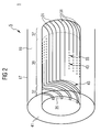
- FIG. 2 schematically shows a preferred embodiment of a stator active part 17 shown in principle in FIG. 1 as part of a stator part 5 not shown further.
- the stator active part 17 according to the new concept is designed such that a turbogenerator 1 according to the new one shown in FIG Concept, a stator winding head 121, as provided in the prior art, is avoided as such.
- a turbogenerator 1 according to the new concept can be designed with a smaller axial extent and is more stable in the region of the front ends of the stator active part 5 than conventional turbogenerators. Vibration excitations, current load and eddy currents in a usually existing stator winding head 121 are thus avoided.
- the stator active part 17 has a ferromagnetic hollow body 19 and stator cables 31 as part of a stator winding 33 and a switching line connection, not shown.
- a symbolically shown interconnection 35 of the stator 31 is still arranged according to the new concept in the region of the ferromagnetic hollow body 19, ie in the active part of the turbogenerator 1.
- the stator winding 33 in the form of a number of along the ferromagnetic hollow body 19 arranged stator conductors 31 formed.
- a stator 31 has a arranged in the wall 41 of the ferromagnetic hollow body 19 straight line 43 in a center region 39 lying between the end-side end portions 37 of the ferromagnetic hollow body.
- the straight course is taken up by a groove not shown in the wall 41 of the ferromagnetic hollow body 19.
- a stator 31 has a winding path 45 leading out of the wall 41 of the ferromagnetic hollow body 19.
- the winding course in the preferred embodiment shown in FIG 2 is disposed radially within the wall 41 of the ferromagnetic hollow body.
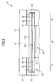
- the courses 43, 45 are shown more clearly in the sectional view of FIG. 3 for the particularly preferred embodiment of a stator active part 17 shown in FIG.
- the same reference numerals as in FIG 2 are used.
- the central region 39 of the ferromagnetic hollow body 19 is offset at an angle 47 from the end-side end regions 37 of the ferromagnetic hollow body 19. In the angle, the ends 49 of a stator 510, 51U, so in a portion of the tortuous path 45, mounted with an insulating material 53.
- a stator conductor 510 is arranged in a top layer of a two-layer arrangement of a stator winding 33, and a stator conductor 51U is arranged in a base of a two-layer arrangement of a stator winding 33.
- the stator conductors 510, 51U are electrically connected to each other at their ends 49 by an interconnection 35.
- the interconnection 35 still takes place in the region of the stator active part 17.
- the interconnection can also switch the different winding arrangements in series or in parallel as required. These rods are depending on the suitability z. B. soldered, glued or screwed.
- a stator part of a turbogenerator 1 has a stator active part 17, which has a ferromagnetic hollow body and stator conductor 31.
- a stator winding head is usually provided, in which a complex connection of the rods in combination with stiffening and support elements is provided.
- Such a stator winding head is avoided according to the new concept, in principle, by arranging an interconnection of the stator conductors 31 in the region of the ferromagnetic hollow body 19. This will be a compact and axially shortened Construction of turbogenerators 1 and a better mechanical stability in the end region of the stator 5 achieved. Eddy current losses, which usually occur at the end faces 37 of the stator 5 in the stator winding head, are avoided by avoiding the stator winding head as such.
Landscapes
- Engineering & Computer Science (AREA)
- Power Engineering (AREA)
- Windings For Motors And Generators (AREA)
Priority Applications (1)
| Application Number | Priority Date | Filing Date | Title |
|---|---|---|---|
| EP05014886A EP1742331A1 (fr) | 2005-07-08 | 2005-07-08 | Stator d'un turboalternateur et turboalternateur |
Applications Claiming Priority (1)
| Application Number | Priority Date | Filing Date | Title |
|---|---|---|---|
| EP05014886A EP1742331A1 (fr) | 2005-07-08 | 2005-07-08 | Stator d'un turboalternateur et turboalternateur |
Publications (1)
| Publication Number | Publication Date |
|---|---|
| EP1742331A1 true EP1742331A1 (fr) | 2007-01-10 |
Family
ID=35134099
Family Applications (1)
| Application Number | Title | Priority Date | Filing Date |
|---|---|---|---|
| EP05014886A Withdrawn EP1742331A1 (fr) | 2005-07-08 | 2005-07-08 | Stator d'un turboalternateur et turboalternateur |
Country Status (1)
| Country | Link |
|---|---|
| EP (1) | EP1742331A1 (fr) |
Cited By (1)
| Publication number | Priority date | Publication date | Assignee | Title |
|---|---|---|---|---|
| EP2871754A1 (fr) * | 2013-11-12 | 2015-05-13 | Siemens Aktiengesellschaft | Machine électrique |
Citations (2)
| Publication number | Priority date | Publication date | Assignee | Title |
|---|---|---|---|---|
| US6157109A (en) * | 1998-02-10 | 2000-12-05 | Reliance Electric Technologies, Llc | Dynamoelectric machine with ferromagnetic end winding ring |
| US20020027396A1 (en) * | 1999-01-20 | 2002-03-07 | Siemens Ag | Rotating electrical machine having a permanent-magnet rotor |
-
2005
- 2005-07-08 EP EP05014886A patent/EP1742331A1/fr not_active Withdrawn
Patent Citations (2)
| Publication number | Priority date | Publication date | Assignee | Title |
|---|---|---|---|---|
| US6157109A (en) * | 1998-02-10 | 2000-12-05 | Reliance Electric Technologies, Llc | Dynamoelectric machine with ferromagnetic end winding ring |
| US20020027396A1 (en) * | 1999-01-20 | 2002-03-07 | Siemens Ag | Rotating electrical machine having a permanent-magnet rotor |
Cited By (1)
| Publication number | Priority date | Publication date | Assignee | Title |
|---|---|---|---|---|
| EP2871754A1 (fr) * | 2013-11-12 | 2015-05-13 | Siemens Aktiengesellschaft | Machine électrique |
Similar Documents
| Publication | Publication Date | Title |
|---|---|---|
| EP3134960B1 (fr) | Moteur électrique | |
| EP1811634B1 (fr) | Réfrigérateur doté d'un dispositif de production de glace | |
| EP1064712B1 (fr) | Moteur a flux transversal polyphase | |
| EP1574708B1 (fr) | Installation d'énergie éolienne à génératrice annulaire | |
| EP1974439A1 (fr) | Machine électrique comprenant un système d'enroulement à trois faisceaux | |
| EP1742330B1 (fr) | Tête de bobine d'un stator, stator d'une machine électrique et turboalternateur | |
| EP3352341B1 (fr) | Stator et procédé de fabrication d'un stator | |
| EP3207619B1 (fr) | Stator de machine électrique | |
| WO2003063322A2 (fr) | Ensemble stator | |
| DE2455001C2 (de) | Wicklungsanordnung für eine nutenlose umlaufende elektrische Maschine | |
| WO2015144494A1 (fr) | Machine électrique | |
| DE69716729T2 (de) | Wicklung für den stator einer rotierenden elektrischen maschine sowie eine derartige maschine | |
| DE102012214523B4 (de) | Ständer oder Ständersegment einer dynamoelektrischen Maschine mit optimiertem Wickelkopf, dynamoelektrische Maschine und Rohrmühle oder Windkraftgenerator | |
| EP2276149B1 (fr) | Schéma d'enroulement pour un support segmenté d'une machine dynamoélectrique | |
| DE19846923C1 (de) | Mehrphasige Wicklung einer elektrischen Maschine und Verfahren zu ihrer Herstellung | |
| DE2913844C2 (de) | Nutisolierung für den Rotor einer elektrischen Maschine | |
| DE29500878U1 (de) | Elektrische Wechselspannungsmaschine mit einem dauermagneterregten Läufer | |
| EP1742329A1 (fr) | Stator d'un turboalternateur et turboalternateur | |
| DE10061045A1 (de) | Mehrphasige elektrische Maschine | |
| EP2979351B1 (fr) | Rotor pour moteur electrique | |
| EP3900156A1 (fr) | Empilage de tôles pour machine électrique | |
| DE1090749B (de) | Asynchronmaschine in Turbobauart, insbesondere Asynchronmaschine grosser Leistung mit geringer Polzahl | |
| DE1613787A1 (de) | Einphasen-Asynchronmotor | |
| DE4428040C1 (de) | Ständer einer elektrischen Maschine | |
| EP2228888A1 (fr) | Rotor pour un turbogénérateur et turbogénérateur doté d'un rotor |
Legal Events
| Date | Code | Title | Description |
|---|---|---|---|
| PUAI | Public reference made under article 153(3) epc to a published international application that has entered the european phase |
Free format text: ORIGINAL CODE: 0009012 |
|
| AK | Designated contracting states |
Kind code of ref document: A1 Designated state(s): AT BE BG CH CY CZ DE DK EE ES FI FR GB GR HU IE IS IT LI LT LU LV MC NL PL PT RO SE SI SK TR |
|
| AX | Request for extension of the european patent |
Extension state: AL BA HR MK YU |
|
| AKX | Designation fees paid | ||
| STAA | Information on the status of an ep patent application or granted ep patent |
Free format text: STATUS: THE APPLICATION IS DEEMED TO BE WITHDRAWN |
|
| 18D | Application deemed to be withdrawn |
Effective date: 20070711 |
|
| REG | Reference to a national code |
Ref country code: DE Ref legal event code: 8566 |