EP1742577B1 - Support a libre acces sur patins pneumatiques - Google Patents
Support a libre acces sur patins pneumatiques Download PDFInfo
- Publication number
- EP1742577B1 EP1742577B1 EP05718597.7A EP05718597A EP1742577B1 EP 1742577 B1 EP1742577 B1 EP 1742577B1 EP 05718597 A EP05718597 A EP 05718597A EP 1742577 B1 EP1742577 B1 EP 1742577B1
- Authority
- EP
- European Patent Office
- Prior art keywords
- scanner
- common
- race
- bore
- set forth
- Prior art date
- Legal status (The legal status is an assumption and is not a legal conclusion. Google has not performed a legal analysis and makes no representation as to the accuracy of the status listed.)
- Expired - Lifetime
Links
- 238000003384 imaging method Methods 0.000 claims description 11
- 230000005855 radiation Effects 0.000 claims description 10
- 230000000712 assembly Effects 0.000 claims description 6
- 238000000429 assembly Methods 0.000 claims description 6
- 230000005540 biological transmission Effects 0.000 claims description 6
- 238000000034 method Methods 0.000 claims description 6
- 239000000835 fiber Substances 0.000 claims description 5
- 238000004519 manufacturing process Methods 0.000 claims description 4
- 230000006698 induction Effects 0.000 claims description 2
- 238000002591 computed tomography Methods 0.000 description 23
- 238000013461 design Methods 0.000 description 13
- 230000008901 benefit Effects 0.000 description 7
- 230000003287 optical effect Effects 0.000 description 6
- XEEYBQQBJWHFJM-UHFFFAOYSA-N Iron Chemical compound [Fe] XEEYBQQBJWHFJM-UHFFFAOYSA-N 0.000 description 4
- 238000012546 transfer Methods 0.000 description 4
- 238000002059 diagnostic imaging Methods 0.000 description 3
- 230000004075 alteration Effects 0.000 description 2
- 238000005516 engineering process Methods 0.000 description 2
- 229910052742 iron Inorganic materials 0.000 description 2
- 238000012986 modification Methods 0.000 description 2
- 230000004048 modification Effects 0.000 description 2
- 241000238876 Acari Species 0.000 description 1
- OKTJSMMVPCPJKN-UHFFFAOYSA-N Carbon Chemical compound [C] OKTJSMMVPCPJKN-UHFFFAOYSA-N 0.000 description 1
- 230000001133 acceleration Effects 0.000 description 1
- XAGFODPZIPBFFR-UHFFFAOYSA-N aluminium Chemical compound [Al] XAGFODPZIPBFFR-UHFFFAOYSA-N 0.000 description 1
- 229910052782 aluminium Inorganic materials 0.000 description 1
- 229910052799 carbon Inorganic materials 0.000 description 1
- 238000005266 casting Methods 0.000 description 1
- 238000004891 communication Methods 0.000 description 1
- 239000002131 composite material Substances 0.000 description 1
- 238000013170 computed tomography imaging Methods 0.000 description 1
- 239000002537 cosmetic Substances 0.000 description 1
- 239000000428 dust Substances 0.000 description 1
- 230000008030 elimination Effects 0.000 description 1
- 230000007613 environmental effect Effects 0.000 description 1
- 238000005530 etching Methods 0.000 description 1
- 238000003754 machining Methods 0.000 description 1
- 238000005259 measurement Methods 0.000 description 1
- 230000007246 mechanism Effects 0.000 description 1
- 230000002093 peripheral effect Effects 0.000 description 1
- 238000007639 printing Methods 0.000 description 1
- 230000001360 synchronised effect Effects 0.000 description 1
- WFKWXMTUELFFGS-UHFFFAOYSA-N tungsten Chemical compound [W] WFKWXMTUELFFGS-UHFFFAOYSA-N 0.000 description 1
- 229910052721 tungsten Inorganic materials 0.000 description 1
- 239000010937 tungsten Substances 0.000 description 1
- 238000004804 winding Methods 0.000 description 1
Images


Classifications
-
- A—HUMAN NECESSITIES
- A61—MEDICAL OR VETERINARY SCIENCE; HYGIENE
- A61B—DIAGNOSIS; SURGERY; IDENTIFICATION
- A61B6/00—Apparatus or devices for radiation diagnosis; Apparatus or devices for radiation diagnosis combined with radiation therapy equipment
- A61B6/44—Constructional features of apparatus for radiation diagnosis
- A61B6/4411—Constructional features of apparatus for radiation diagnosis the apparatus being modular
-
- A—HUMAN NECESSITIES
- A61—MEDICAL OR VETERINARY SCIENCE; HYGIENE
- A61B—DIAGNOSIS; SURGERY; IDENTIFICATION
- A61B6/00—Apparatus or devices for radiation diagnosis; Apparatus or devices for radiation diagnosis combined with radiation therapy equipment
- A61B6/02—Arrangements for diagnosis sequentially in different planes; Stereoscopic radiation diagnosis
- A61B6/025—Tomosynthesis
-
- A—HUMAN NECESSITIES
- A61—MEDICAL OR VETERINARY SCIENCE; HYGIENE
- A61B—DIAGNOSIS; SURGERY; IDENTIFICATION
- A61B6/00—Apparatus or devices for radiation diagnosis; Apparatus or devices for radiation diagnosis combined with radiation therapy equipment
- A61B6/02—Arrangements for diagnosis sequentially in different planes; Stereoscopic radiation diagnosis
- A61B6/03—Computed tomography [CT]
- A61B6/032—Transmission computed tomography [CT]
-
- A—HUMAN NECESSITIES
- A61—MEDICAL OR VETERINARY SCIENCE; HYGIENE
- A61B—DIAGNOSIS; SURGERY; IDENTIFICATION
- A61B6/00—Apparatus or devices for radiation diagnosis; Apparatus or devices for radiation diagnosis combined with radiation therapy equipment
- A61B6/02—Arrangements for diagnosis sequentially in different planes; Stereoscopic radiation diagnosis
- A61B6/03—Computed tomography [CT]
- A61B6/032—Transmission computed tomography [CT]
- A61B6/035—Mechanical aspects of CT
-
- A—HUMAN NECESSITIES
- A61—MEDICAL OR VETERINARY SCIENCE; HYGIENE
- A61B—DIAGNOSIS; SURGERY; IDENTIFICATION
- A61B6/00—Apparatus or devices for radiation diagnosis; Apparatus or devices for radiation diagnosis combined with radiation therapy equipment
- A61B6/54—Control of apparatus or devices for radiation diagnosis
- A61B6/547—Control of apparatus or devices for radiation diagnosis involving tracking of position of the device or parts of the device
-
- A—HUMAN NECESSITIES
- A61—MEDICAL OR VETERINARY SCIENCE; HYGIENE
- A61B—DIAGNOSIS; SURGERY; IDENTIFICATION
- A61B6/00—Apparatus or devices for radiation diagnosis; Apparatus or devices for radiation diagnosis combined with radiation therapy equipment
- A61B6/56—Details of data transmission or power supply, e.g. use of slip rings
-
- G—PHYSICS
- G01—MEASURING; TESTING
- G01N—INVESTIGATING OR ANALYSING MATERIALS BY DETERMINING THEIR CHEMICAL OR PHYSICAL PROPERTIES
- G01N23/00—Investigating or analysing materials by the use of wave or particle radiation, e.g. X-rays or neutrons, not covered by groups G01N3/00 – G01N17/00, G01N21/00 or G01N22/00
- G01N23/02—Investigating or analysing materials by the use of wave or particle radiation, e.g. X-rays or neutrons, not covered by groups G01N3/00 – G01N17/00, G01N21/00 or G01N22/00 by transmitting the radiation through the material
- G01N23/04—Investigating or analysing materials by the use of wave or particle radiation, e.g. X-rays or neutrons, not covered by groups G01N3/00 – G01N17/00, G01N21/00 or G01N22/00 by transmitting the radiation through the material and forming images of the material
- G01N23/046—Investigating or analysing materials by the use of wave or particle radiation, e.g. X-rays or neutrons, not covered by groups G01N3/00 – G01N17/00, G01N21/00 or G01N22/00 by transmitting the radiation through the material and forming images of the material using tomography, e.g. computed tomography [CT]
-
- G—PHYSICS
- G01—MEASURING; TESTING
- G01N—INVESTIGATING OR ANALYSING MATERIALS BY DETERMINING THEIR CHEMICAL OR PHYSICAL PROPERTIES
- G01N2223/00—Investigating materials by wave or particle radiation
- G01N2223/40—Imaging
- G01N2223/419—Imaging computed tomograph
-
- G—PHYSICS
- G01—MEASURING; TESTING
- G01N—INVESTIGATING OR ANALYSING MATERIALS BY DETERMINING THEIR CHEMICAL OR PHYSICAL PROPERTIES
- G01N2223/00—Investigating materials by wave or particle radiation
- G01N2223/60—Specific applications or type of materials
- G01N2223/612—Specific applications or type of materials biological material
Definitions
- the present invention relates to the diagnostic imaging arts. It finds particular application in computed tomography, particularly with air bearing systems and will be described with particular reference thereto. However, the invention will also find application in other diagnostic imaging systems.
- a subject In computed tomography (CT) imaging, a subject is positioned on a subject table which moves the subject longitudinally through a bore of a CT scanner.
- An x-ray tube is mounted on a rotating gantry which rotates around the bore to project a fan beam, wedge beam, or cone beam of x-rays through an examination region defined by the bore.
- a one or two-dimensional radiation detector including an array of detector elements is mounted opposite to the x-ray tube to detect and measure intensities of radiation transmitted through the bore.
- a subject disposed in the examination region within the bore interacts with and absorbs a portion of the x-rays.
- the x-ray detector is also mounted on the rotating gantry.
- the x-ray detectors are mounted in a ring on a stationary gantry surrounding the rotating gantry. In either configuration, the intensity data from the x-ray detectors is reconstructed to produce a two or three-dimensional image representation of the portion of the subject in the imaging region in the bore.
- US 2003/0035506 A1 discloses a system for mounting an x-ray tube to a gantry disk of a CT scanner.
- the system is designed to make lifting and handling a heavy and cumbersome x-ray tube easier for a person removing or replacing the x-ray tube in a CT scanner.
- the system includes a harness adapted to be secured to the x-ray tube, at least two elongated rods secured to the harness, and two elongated tracks adapted to be secured to the gantry disk such that the tracks extend generally parallel with a z-axis of the CT scanner.
- Each track includes a channel for slidingly receiving one of the rods.
- the gantry mechanical design is committed to minimizing the patient opening (bore diameter) which can accommodate the subject for which the CT scanner is designed.
- a 30 cm bore may be adequate.
- a 40 or 50 cm bore is adequate.
- an 80-90 cm bore is advantageous.
- the rotating gantry is fit as close as possible to the bore.
- the closer the x-ray tube is to the bore the lower the centrifugal forces on the x-ray tube during rotation at a given speed.
- the rotating anode x-ray tubes used in CT scanners have tungsten anodes which can weigh about 2-4 kg. Operating an x-ray tube at higher centrifugal forces requires different bearings and other designs within the x-ray tube, i. e., higher centrifugal forces require more expensive x-ray tubes.
- the closer the x-ray detector is to the bore the shorter circumferentially the x-ray detector becomes to span a given arc.
- X-ray tubes use large amounts of electrical power, which must be communicated to the rotating gantry. This is typically done by a slip ring positioned as close as possible to the diameter of the bore. In current designs, the larger the diameter of the slip ring, the higher the cost. Moreover, the larger the diameter of the slip ring, the faster the speed between the slip ring and the brushes. The higher relative speeds require higher performance, hence more expensive brushes. Similar considerations apply to the mechanisms for conveying the data accumulated by the rotating detector from the rotating gantry back to the stationary portions of the gantry.
- the reconstruction processor needs an accurate measurement of the angular position of the x-ray source, hence the rotating gantry.
- current designs utilize precision encoders or other angular position measuring devices are typically mounted around the rotating gantry.
- Such angular position encoders or equivalent technology are typically very precise and the longer their circumferential length, the higher their cost becomes.
- the present invention contemplates a new and improved method and apparatus that overcomes the above-referenced problems and others.
- a CT scanner subassembly includes a common stationary gantry frame and a radiation translucent bore of one of a plurality of selectable cross sectional sizes.
- a plurality of common bearing members is mounted to the stationary gantry,
- a common annular bearing race is rotatably supported on the bearing members.
- At least one common motor module rotates the annular bearing race.
- a means mounts an x-ray source and a radiation detector at any of a plurality of selectable distances radially inward from the bearing race such that the common bearing members and the bearing race are used to fabricate CT scanners with any of a plurality of bore sizes.
- a method of fabricating a CT scanner is disclosed as defined in claim 13.
- One advantage of the present invention resides in providing a standard scanner subassembly for different patient apertures.
- Another advantage resides in an easy performance upgrade by adding a larger number of the same modules.
- the invention may take form in various components and arrangements of components, and in various steps and arrangements of steps.
- the drawings are only for purposes of illustrating the preferred embodiments and are not to be construed as limiting the invention.
- a computed tomography (CT) imaging apparatus or scanner 10 includes a stationary gantry 12 that supports a rotating gantry 14.
- the stationary gantry 12 is sized to fit through the doorways or other portals into conventional imaging suites.
- An x-ray source such as x-ray tube 16 and a source collimator 18 cooperate to produce a fan-shaped, cone-shaped, wedge-shaped, or otherwise-shaped x-ray beam directed across an examination region 20 to an array of x-ray detectors 22.
- the x-ray detectors 22 are mounted on the rotating gantry 14.
- the examination region 20 is defined within a cosmetic radiotranslucent bore or bezel 24 attached to the stationary gantry 12 to shield a subject from moving parts.
- a resolver or encoder 26 determines an angular orientation of the rotating gantry as it is rotated by one or more motors 28 on high speed bearings such as air bearings, magnetic bearings, or the like.
- a subject support or patient couch 30 is driven by a motor 32 to move longitudinally along Z-axis into and through the examination region 20.
- a motor 32 to move longitudinally along Z-axis into and through the examination region 20.
- at least part of the patient couch is partially or completely radiotranslucent.
- Projection data which are collected by the detector 22 are communicated to a digital data memory 40.
- a reconstruction processor 42 reconstructs the acquired projection data, using filtered backprojection, an n-PI reconstruction method, or other reconstruction method, to generate a three-dimensional image representation of the subject or of selected portion thereof which is stored in a volumetric image memory 44.
- the image representation is rendered or otherwise manipulated by a video processor 46 to produce a human-viewable image that is displayed on a graphical user interface 48 or another display device, printing device, or the like for viewing by an operator.
- the graphical user interface 48 is programmed to interface a human operator with the CT scanner 10 to allow the operator to initialize, execute, and control CT imaging sessions.
- the graphical user interface 48 is optionally interfaced with a communication network such as a hospital or clinic information network via which image reconstructions are transmitted to medical personnel, a patient information database is accessed, and the like.
- the rotating gantry 14 is suspended from the stationary gantry 12 by a plurality of air bearing pads 50 as described in a great detail in US Patent No. 6,404,845 issued to Phillips Medical Systems.
- the air bearing pads 50 support an outer circumferential surface or air bearing race 52 of an aluminum rotor 54 of the rotating gantry 14 on a thin cushion of air to provide a nearly frictionless surface for the rotating gantry, thus making the bearing suitable for high speed rotation at reasonable system cost.
- FIGURES 2A-2B various common components, which are normally used in CT scanners, are mounted on the rotating gantry 14.
- the motor(s) 28, power slip ring and brush assemblies 56, encoder 26, information transmission assemblies 58, x-ray tube 16, detector 22 and other components are mounted in available areas of the air bearing system, adjacent or along the air bearing race 52. Placing the x-ray tube 16 and detector 22 near the rotor outer surface 52, as shown in FIGURE 2A , defines a large bore scanner. Mounting the x-ray tube 16 and the detector 22 closer together, as shown in FIGURE 2B , defines a smaller bore scanner.
- the air pads 50 are mounted on side periphery 60 of the air bearing race 52 which has a pair of converging bearing surfaces. In this embodiment, the same pads provide both radial and lateral support and guidance.
- the motor 28 is mounted about an outer ring 62 of the race 52.
- the motor 28 is a linear induction motor (LIM) which is a segmented module spanning several degrees of arc.
- LIM linear induction motor
- the motor 28 induces counter-acting magnetic fields in the race 52 which are used for propulsion. More motor modules 28 are added along the race 52 for CT scanner models in which the gantry is accelerated more rapidly.
- the iron is added on or underlying the air bearing race surface that interacts with the linear motor 28 to improve efficiency.
- magnets or windings of the linear motors 28 are embedded in the race 52. In this design, optionally, synchronous ring motors are preferably used.
- the power slip ring and brush assembly 56 is mounted about the race 52. More specifically, a power slip ring or segment 68 is positioned about the outer ring 62 of the race 52.
- the power slip ring 68 can be a continuous concentric ring, it is preferably not a continuous ring but rather one or more segments 68 which span circumferentially around the race 52 such that at least one stationary power brush assembly 70 contacts each slip ring segment 68 at any given time.
- the more segments are used, the fewer brush holders per segment are needed to supply the electric power required.
- the opposite is also true, e.g. if the fewer number of segments is used, the more brush holders per segment are required.
- Each power brush assembly 70 includes a holder and a plurality of fiber wires (not shown) secured in the holder as described in U.S. Patent No. 4,360,699 and U.S. Patent No. 4,415,635 issued to the University of Virginia.
- the fiber wires contact the slip ring 68 via a radial mount.
- the fiber wire brushes enable the brush assembly 70 and the slip ring segment(s) 68 to move at any speed up to about 152.5 linear m/sec relative to each other.
- the fiber brush has a minimal wear, allowing the lifetime of hundreds millions of revolutions and virtual elimination of brush dust associated with carbon composite brushes utilized in many CT scanner slipring designs.
- the slip ring segment design provides more flexibility, ease of mounting and replacement and significant cost savings over present CT scanner slipring design. More like brush holders and/or like power slip segments are added for CT scanner models with higher power x-rays tubes, once again, in a modular, cost-effective fashion, without changing the gantry design.
- rotating transformers can be used to transfer the electric power inductively.
- the rotating portion of the transformer can be unified with the air bearing race.
- the information transmission assembly 58 is disposed about the race 52.
- Elliptical lenses 72 and light receivers or detectors 74 are stationary mounted along portions of the air bearing race 52 to receive light from a line of diodes 76 which are positioned around a peripheral surface.
- Each lens 72 extends over several degrees of arc and is designed to focus the light received at any point under the lens onto a common focal spot, e.g. the path to the focal point is constant and independent of the position of the rotating gantry 14.
- the stationary gantry 12 is divided into quadrants with a single light-collecting assembly 72, 74 mounted in each.
- the light sources i.e.
- light emitting diodes 76 are positioned on the rotating portion, such that at least one light emitting diode is optically connected to the light collecting assembly 72, 74 at any point in time.
- Four light collecting assemblies and a single circumferential line of light sources are sufficient to match at least the 5.3 gigabits/second data transfer rate of a current forty slice scanner.
- the collecting assemblies might be modularly added to increase the data transfer rate.
- the rotating gantry 14 is split into equal segments with the light sources currently in each quadrant operating in unison such that their lenses are equi-spaced around the air bearing race 52.
- the data transfer rate is increased by utilizing sources with higher optical power output, and/or by using wave division multiplexing, and/or by electronically switching the light sources according to the quadrant the light sources are in, such that a contiguous channel is received by each light collecting assembly.
- a bi-directional optical control link between the rotating portion of the gantry and its stator is implemented. This link can also be partially realized within the optical HW of the information transmission assembly.
- the resolver or encoder 26 is disposed about the outer ring 62 of the race 52.
- the encoder 26 includes a plurality of tick marks or other regularly spaced timing elements 80 circumferentially spanning 360 degrees around the race 52.
- the tick marks 80 are etched in or otherwise attached to the race 52.
- An optical read head 82 reads the tick marks 80 as the rotating gantry 14 rotates and determines the angular position of the rotating gantry 14.
- the air bearing race 52 has a rectangular cross-section.
- the air bearing pads 50 are mounted on the side periphery 60 and a radially outmost surface 84 of the race 52.
- Annular supports 86, 88 are extended from the race side periphery 60 to provide an annular mounting means or surface for the power slip rings 68, the encoder ring 26 and other appropriate components.
- the linear motors 28 can be coupled to one of the annular supports 86, 88 or can be interposed between the air bearings pads 50 to interact with the circumferential bearing surface or an underlying layer with more iron content.
- the power slip rings 68 are mounted on the race side periphery 60 and the outmost surface 84.
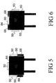
- the power slip rings 68 might be mounted on the outer periphery of the rotor wherever space allows. Note that the position encoders and motors remain the same as shown in Figures 2A and 2B .
Landscapes
- Health & Medical Sciences (AREA)
- Life Sciences & Earth Sciences (AREA)
- Engineering & Computer Science (AREA)
- Medical Informatics (AREA)
- Pathology (AREA)
- General Health & Medical Sciences (AREA)
- Physics & Mathematics (AREA)
- Nuclear Medicine, Radiotherapy & Molecular Imaging (AREA)
- Radiology & Medical Imaging (AREA)
- Surgery (AREA)
- Veterinary Medicine (AREA)
- Biomedical Technology (AREA)
- Heart & Thoracic Surgery (AREA)
- Molecular Biology (AREA)
- High Energy & Nuclear Physics (AREA)
- Animal Behavior & Ethology (AREA)
- Biophysics (AREA)
- Public Health (AREA)
- Optics & Photonics (AREA)
- Pulmonology (AREA)
- Theoretical Computer Science (AREA)
- Chemical & Material Sciences (AREA)
- Analytical Chemistry (AREA)
- Biochemistry (AREA)
- General Physics & Mathematics (AREA)
- Immunology (AREA)
- Computer Networks & Wireless Communication (AREA)
- Apparatus For Radiation Diagnosis (AREA)
Claims (17)
- Sous-ensemble tomodensitomètre comprenant :un châssis de portique immobile commun (12) ;un tunnel radiotransparent (24) de l'une d'une pluralité de tailles en coupe transversale pouvant être sélectionnées ;une pluralité d'éléments formant paliers communs (50) montés sur le portique immobile (12) ;un chemin de roulement de palier annulaire commun (52) soutenu en rotation sur les éléments formant paliers (50) ;au moins un module moteur commun (28) pour faire tourner le chemin de roulement de palier annulaire (52) ; etun moyen (100) pour monter une source de rayons X (16) et un détecteur de rayonnement (22) à n'importe laquelle d'une pluralité de distances pouvant être sélectionnées de façon radiale vers l'intérieur à partir du chemin de roulement de palier (52) de sorte que les éléments formant paliers communs (50) et le chemin de roulement de palier (52) sont utilisés pour fabriquer des tomodensitomètres ayant n'importe laquelle d'une pluralité de tailles de tunnel.
- Tomodensitomètre selon la revendication 1, dans lequel le chemin de roulement (52) a l'une d'une section transversale triangulaire et rectangulaire.
- Tomodensitomètre selon la revendication 1, dans lequel l'au moins un module moteur commun (28) inclut un module moteur à induction linéaire (LIM).
- Tomodensitomètre selon la revendication 1, incluant en outre : plusieurs modules moteurs pour accélérer plus rapidement le chemin de roulement de palier (52).
- Tomodensitomètre selon la revendication 1, dans lequel l'au moins un module moteur (28) est incorporé dans le chemin de roulement (52).
- Tomodensitomètre selon la revendication 1, incluant en outre :
un ensemble bague collectrice de courant commun (56) disposée autour du chemin de roulement (52), qui fournit du courant électrique au moins à l'au moins un moteur (28), chaque ensemble bague collectrice (56) incluant au moins :une section bague collectrice de courant annulaire (68) disposée au niveau du chemin de roulement (52) ; etau moins deux supports de balai (70) montés sur le châssis immobile (12). - Tomodensitomètre selon la revendication 6, incluant en outre : une pluralité de balais métalliques à fibres fixés dans chaque support (70).
- Tomodensitomètre selon la revendication 6, incluant en outre : une pluralité des ensembles bagues collectrices de courant (56).
- Tomodensitomètre selon la revendication 1, incluant en outre : des ensembles de transmission d'informations (58) disposés autour de portions du chemin de roulement (52) pour émettre et recevoir des données, chaque ensemble de transmission d'informations (58) incluant :plusieurs émetteurs (76) disposés sur le chemin de roulement (52) ; etplusieurs récepteurs (74) disposés sur le châssis immobile (12).
- Tomodensitomètre selon la revendication 9, incluant en outre : au moins une lentille elliptique (72) qui reçoit des rayons lumineux en provenance des émetteurs (76) et qui concentre les rayons lumineux reçus jusque dans un foyer commun.
- Tomodensitomètre selon la revendication 10, dans lequel le chemin de roulement de palier à air commun (52) est divisé en quadrants et incluant en outre :
une lentille particulière (72) positionnée dans chaque quadrant associé de sorte que lorsque le chemin de roulement de palier (52) tourne au moins une diode électroluminescente (76) est positionnée sous la lentille particulière (72) dans chaque quadrant. - Tomodensitomètre selon la revendication 1, incluant en outre :une pluralité d'éléments de synchronisation (80) disposés sur le chemin de roulement (52) ; etun capteur de lecture (82) disposé sur le portique immobile (12) pour lire une position des éléments de synchronisation (80).
- Procédé de fabrication d'un tomodensitomètre (10) comprenant :la fabrication d'un sous-ensemble commun pour le tomodensitomètre ;la sélection d'un tunnel (24) d'un diamètre approprié ;le montage du tunnel du diamètre sélectionné sur le sous-ensemble commun ; etle montage d'un tube à rayons X (16) et d'un groupement de détecteurs de rayonnement (22) sur le sous-ensemble commun, dans lequel le sous-ensemble commun inclut :un châssis de portique immobile commun (12) ;une pluralité d'éléments formant paliers communs (50) montés sur le portique immobile (12) ;un chemin de roulement de palier annulaire commun (52) soutenu en rotation sur les éléments formant paliers (50) ;au moins un module moteur commun (28) pour faire tourner le chemin de roulement de palier annulaire (52) ; etun moyen (100) pour monter la source de rayons X (16) et le groupement de détecteurs de rayonnement (22) à n'importe laquelle d'une pluralité de distances pouvant être sélectionnées.
- Procédé selon la revendication 13, incluant en outre :la sélection d'un type d'un module moteur ; etle montage de plusieurs modules moteurs sur le sous-ensemble commun.
- Procédé selon la revendication 13, incluant en outre :
sur la base du diamètre de tunnel sélectionné, le montage du tube à rayons X et du groupement de détecteurs de sorte que le tube à rayons X et le groupement de détecteurs sont montés aussi près que possible l'un de l'autre et du tunnel. - Procédé selon la revendication 13, incluant en outre :sur la base du diamètre de tunnel sélectionné, la sélection d'une taille du tube à rayons X et d'une longueur du groupement de détecteurs ; etla sélection d'une distance montante entre le tube à rayons X et le groupement de détecteurs.
- Système d'imagerie modulaire standardisée adaptable incluant :un châssis de portique immobile standard (12) ;un tunnel radiotransparent (24) ayant l'un d'une pluralité de diamètres spécifiés ;une pluralité d'éléments formant paliers standards (50) montés sur le portique immobile (12) ;un chemin de roulement de palier annulaire standard (52) soutenu en rotation sur les éléments formant paliers (50) ;une variété de modules standards disposés autour du chemin de roulement (52), chacun des modules pouvant être ajouté de façon modulaire, laquelle variété inclut un ou plus de :modules moteurs standards (28) pour faire tourner le chemin de roulement de palier annulaire (52),modules de bagues collectrices de courant standards (56) pour fournir du courant électrique aux parties tournantes du système d'imagerie, etmodules de bagues collectrices de transmission d'informations standards (58) pour émettre des données vers les parties tournantes du système d'imagerie et recevoir les données en provenance de celles-ci ; etun moyen (100) pour monter une source de rayons X (16) et un détecteur de rayonnement (22) à n'importe laquelle d'une pluralité de distances pouvant être sélectionnées de façon radiale vers l'intérieur à partir du chemin de roulement de palier (52) de sorte que les éléments formant paliers standards (50) et le chemin de roulement de palier standard (52) sont utilisés pour fabriquer des tomodensitomètres ayant n'importe lequel de la pluralité de diamètres de tunnel.
Applications Claiming Priority (2)
| Application Number | Priority Date | Filing Date | Title |
|---|---|---|---|
| US56556104P | 2004-04-27 | 2004-04-27 | |
| PCT/IB2005/051070 WO2005102171A1 (fr) | 2004-04-27 | 2005-03-30 | Support a libre acces sur patins pneumatiques |
Publications (2)
| Publication Number | Publication Date |
|---|---|
| EP1742577A1 EP1742577A1 (fr) | 2007-01-17 |
| EP1742577B1 true EP1742577B1 (fr) | 2019-05-08 |
Family
ID=34962021
Family Applications (1)
| Application Number | Title | Priority Date | Filing Date |
|---|---|---|---|
| EP05718597.7A Expired - Lifetime EP1742577B1 (fr) | 2004-04-27 | 2005-03-30 | Support a libre acces sur patins pneumatiques |
Country Status (5)
| Country | Link |
|---|---|
| US (1) | US7477721B2 (fr) |
| EP (1) | EP1742577B1 (fr) |
| JP (1) | JP2007534413A (fr) |
| CN (1) | CN1946343B (fr) |
| WO (1) | WO2005102171A1 (fr) |
Families Citing this family (27)
| Publication number | Priority date | Publication date | Assignee | Title |
|---|---|---|---|---|
| EP3175886B1 (fr) | 2005-07-23 | 2018-06-27 | TomoTherapy, Inc. | Imagerie de radiothérapie et administration de radiothérapie par déplacement coordonné du portique et de la table |
| DE102006037543B4 (de) * | 2006-08-10 | 2009-08-27 | Aerolas Gmbh, Aerostatische Lager- Lasertechnik | Vorrichtung mit einem direkt angetriebenen Rotationskörper und aerostatisches Lager |
| US8052327B2 (en) * | 2007-06-04 | 2011-11-08 | Ntn Corporation | Hydrostatic gas bearing, rotator and CT scanner |
| JP5575666B2 (ja) * | 2008-02-22 | 2014-08-20 | コーニンクレッカ フィリップス エヌ ヴェ | 分散型線源によるx線イメージングのための高解像度の略静的セットアップ |
| DE102008041151B4 (de) * | 2008-08-11 | 2012-11-08 | Schleifring Und Apparatebau Gmbh | CT Scanner Gantry mit aerostatischem Lager und segmentiertem Ringmotor |
| US8118488B2 (en) | 2009-01-05 | 2012-02-21 | Mobius Imaging, Llc | Mobile medical imaging system and methods |
| JP5816095B2 (ja) | 2009-01-09 | 2015-11-18 | コーニンクレッカ フィリップス エヌ ヴェKoninklijke Philips N.V. | 撮像システム・ガントリー |
| WO2010093357A1 (fr) * | 2009-02-11 | 2010-08-19 | Tomotherapy Incorporated | Ensemble support de cible et procédé de protection de la cible |
| RU2543972C2 (ru) * | 2009-04-15 | 2015-03-10 | Конинклейке Филипс Электроникс Н.В. | Привод с изогнутым линейным асинхронным двигателем |
| EP2316342A1 (fr) * | 2009-09-18 | 2011-05-04 | Güdel Group AG | Système de support pour appareils à scanner |
| DE102010015061B4 (de) | 2010-04-15 | 2020-04-23 | Siemens Healthcare Gmbh | Vorrichtung zur Lagerung und zum Antrieb eines rotierbaren Teils einer Gantry eines Computertomographiegerätes und Computertomographiegerät |
| DE102010015062B4 (de) | 2010-04-15 | 2018-10-25 | Siemens Healthcare Gmbh | Vorrichtung zur Lagerung und zum Antrieb eines kippbaren Teils einer Gantry eines Computertomographiegerätes und Computertomographiegerät |
| DE102010041836A1 (de) * | 2010-10-01 | 2012-04-05 | Siemens Aktiengesellschaft | Anordnung zur kontaktlosen Leistungsübertragung und kontaktloser Datenübertragung in einer Computertomographieanlage |
| US8562211B2 (en) * | 2011-03-30 | 2013-10-22 | Medtronic Navigation, Inc. | System and method for off-center imaging |
| KR20130057653A (ko) * | 2011-11-24 | 2013-06-03 | 삼성전자주식회사 | 의료영상기기 |
| EP2962309B1 (fr) | 2013-02-26 | 2022-02-16 | Accuray, Inc. | Collimateur multilame actionné par voie électromagnétique |
| DE102013221169B4 (de) | 2013-10-18 | 2017-06-08 | Siemens Healthcare Gmbh | Rotor mit einem Rückwandbus umfassend elektrische Verbindungselemente zur elektrischen Kontaktierung mit elektrischen Komponenten in einem medizinischen Gerät sowie Dreheinheit und medizinisches Gerät mit einem solchen Rotor |
| DE102013224886B4 (de) * | 2013-12-04 | 2021-07-29 | Siemens Healthcare Gmbh | Lagerung eines Rotors einer Gantry eines bildgebenden medizintechnischen Geräts |
| US9254108B2 (en) * | 2014-03-18 | 2016-02-09 | General Electric Company | Gantry with bore safety mechanism |
| DE102014214511A1 (de) * | 2014-07-24 | 2016-01-28 | Siemens Aktiengesellschaft | Vorrichtung mit einer Gantry |
| US10326561B2 (en) * | 2015-06-24 | 2019-06-18 | Toshiba Medical Systems Corporation | Mirror-ring assembly for bi-directional optical communication between a rotor and a stator |
| US10143427B2 (en) * | 2016-01-27 | 2018-12-04 | General Electric Company | Segmented direct drive motor for use in a computed tomography system |
| US10182777B2 (en) * | 2016-02-22 | 2019-01-22 | Morpho Detection, Llc | Open drum gantry for computed tomography system |
| US10918345B2 (en) * | 2019-07-10 | 2021-02-16 | Analogic Corporation | Assembly for a computer tomography (CT) system and related method |
| CN113740362A (zh) * | 2020-05-29 | 2021-12-03 | 清华大学 | 支撑架和ct检测装置 |
| DE202021104359U1 (de) * | 2021-08-16 | 2021-09-01 | Siemens Healthcare Gmbh | Computertomographie-Gantry mit Näherungsschalter zur Detektion einer Nullposition |
| CN116999079A (zh) * | 2022-04-29 | 2023-11-07 | 上海联影医疗科技股份有限公司 | 医疗设备及其多模态医学成像装置 |
Family Cites Families (27)
| Publication number | Priority date | Publication date | Assignee | Title |
|---|---|---|---|---|
| GB1577172A (en) * | 1976-07-15 | 1980-10-22 | Tokyo Shibaura Electric Co | Tomographing device |
| US4360699A (en) | 1979-12-17 | 1982-11-23 | Ethyl Corporation | Process for preparing a 3-phenoxytoluene and diphenyl ether |
| US4415635A (en) | 1980-04-09 | 1983-11-15 | The University Of Virginia | Electric brush |
| US4358699A (en) | 1980-06-05 | 1982-11-09 | The University Of Virginia Alumni Patents Foundation | Versatile electrical fiber brush and method of making |
| US4799245A (en) | 1983-05-12 | 1989-01-17 | Tokyo Shibaura Denki Kabushiki Kaisha | Integrated CT scanner gantry |
| JPS6145902U (ja) * | 1984-08-30 | 1986-03-27 | 株式会社島津製作所 | Ctスキヤナ |
| US4723259A (en) | 1984-11-05 | 1988-02-02 | Picker International Inc. | Computed tomography motor |
| JPH01503745A (ja) | 1987-07-01 | 1989-12-14 | ムーグ インコーポレーテツド | 光電力伝達制御システム |
| US4912735A (en) * | 1988-07-18 | 1990-03-27 | Elscint Ltd. | Power transfer apparatus particularly for CT scanner |
| EP0381786B1 (fr) * | 1989-02-06 | 1994-04-20 | Siemens Aktiengesellschaft | Dispositif optique pour la transmission de données |
| US5012505A (en) * | 1989-05-19 | 1991-04-30 | Picker International, Inc. | Fluidic slip ring for CT scanners |
| IL90853A0 (en) * | 1989-07-03 | 1990-02-09 | Elscint Ltd | Optical communication link |
| US5185675A (en) | 1989-11-27 | 1993-02-09 | Moog, Inc. | Electro optic modulator systems for fiber optic information transmission |
| US5117445A (en) * | 1990-07-02 | 1992-05-26 | Varian Associates, Inc. | Electronically enhanced x-ray detector apparatus |
| US5703921A (en) | 1995-05-30 | 1997-12-30 | Kabushiki Kaisha Toshiba | X-ray computed tomography apparatus |
| DE69738128T2 (de) | 1996-04-05 | 2008-06-05 | The University Of Virginia Patent Foundation | Metallfaserbürste mit permanentem kontakt |
| DE19629931C2 (de) * | 1996-07-24 | 2000-04-06 | Siemens Ag | Röntgen-Computertomograph |
| US7016457B1 (en) | 1998-12-31 | 2006-03-21 | General Electric Company | Multimode imaging system for generating high quality images |
| JP4495794B2 (ja) * | 1999-04-28 | 2010-07-07 | 株式会社東芝 | 信号伝送装置及びx線ctスキャナ |
| US6327327B1 (en) * | 1999-09-27 | 2001-12-04 | Picker International, Inc. | Multi-channel segmented slip ring |
| US6276145B1 (en) * | 1999-10-27 | 2001-08-21 | Picker International, Inc. | Aerostatic CT suspension |
| US6553091B2 (en) | 2000-06-22 | 2003-04-22 | Kabushiki Kaisha Toshiba | X-ray CT apparatus |
| JP3612264B2 (ja) * | 2000-07-18 | 2005-01-19 | 株式会社東芝 | 回転体・固定体間光伝送装置 |
| US6519312B1 (en) | 2000-08-16 | 2003-02-11 | Analogic Corporation | System and method for mounting x-ray tube in CT scanner |
| US6590953B2 (en) | 2000-09-12 | 2003-07-08 | Hitachi Medical Corporation | X-ray CT scanner |
| US6404845B1 (en) | 2001-05-09 | 2002-06-11 | Philips Medical Systems (Cleveland), Inc. | Aerostatic rotor bearing |
| US6944260B2 (en) * | 2003-11-11 | 2005-09-13 | Ge Medical Systems Global Technology Company, Llc | Methods and apparatus for artifact reduction in computed tomography imaging systems |
-
2005
- 2005-03-30 US US11/568,227 patent/US7477721B2/en not_active Expired - Lifetime
- 2005-03-30 EP EP05718597.7A patent/EP1742577B1/fr not_active Expired - Lifetime
- 2005-03-30 CN CN200580013264XA patent/CN1946343B/zh not_active Expired - Lifetime
- 2005-03-30 JP JP2007510167A patent/JP2007534413A/ja active Pending
- 2005-03-30 WO PCT/IB2005/051070 patent/WO2005102171A1/fr not_active Ceased
Non-Patent Citations (1)
| Title |
|---|
| None * |
Also Published As
| Publication number | Publication date |
|---|---|
| JP2007534413A (ja) | 2007-11-29 |
| WO2005102171A1 (fr) | 2005-11-03 |
| EP1742577A1 (fr) | 2007-01-17 |
| CN1946343B (zh) | 2011-09-07 |
| US7477721B2 (en) | 2009-01-13 |
| CN1946343A (zh) | 2007-04-11 |
| US20070230654A1 (en) | 2007-10-04 |
Similar Documents
| Publication | Publication Date | Title |
|---|---|---|
| EP1742577B1 (fr) | Support a libre acces sur patins pneumatiques | |
| EP0579034B1 (fr) | Appareil de tomodensitométrie à rayons X | |
| EP2915488B1 (fr) | Tomodensitométrie avec un détecteur suivant le mouvement d'une source à rayons x pivotable | |
| US6831961B1 (en) | Combined tomography scanners | |
| US7020233B1 (en) | Dual gantry bearing for combined tomography scanner | |
| JP5736099B2 (ja) | 高回転速度スキャナのための方法及び装置 | |
| US20080175354A1 (en) | Method and apparatus for a c-arm system | |
| US6700947B2 (en) | Apparatus for optically transmitting data between rotor and stator and X-ray CT apparatus having the apparatus incorporated therein | |
| US4008400A (en) | Transverse tomography system having multibeam orbital scanning with all beams offset from the center of orbit | |
| EP1392168A2 (fr) | Palier de rotor aerostatique | |
| GB2250410A (en) | Gantry for nuclear medicine imaging systems with cableless electrical coupling | |
| JP2002533150A (ja) | マルチスライス型イメージング・システム用の画像厚選択法 | |
| EP0181176A2 (fr) | Dispositif de balayage destiné à un appareil de tomographie par ordinateur | |
| US9314220B2 (en) | Rotor and X-ray CT scanners | |
| USRE36099E (en) | X-ray tomography apparatus | |
| JPH02172446A (ja) | コンピユータトモグラフ | |
| US20100036232A1 (en) | Nuclear medicine imaging system having attenuation correction | |
| JPH08107894A (ja) | 回転多陰極ct装置 | |
| JP2001321373A (ja) | カソードスキャン型x線発生器を用いたx線ctスキャナ |
Legal Events
| Date | Code | Title | Description |
|---|---|---|---|
| PUAI | Public reference made under article 153(3) epc to a published international application that has entered the european phase |
Free format text: ORIGINAL CODE: 0009012 |
|
| 17P | Request for examination filed |
Effective date: 20061127 |
|
| AK | Designated contracting states |
Kind code of ref document: A1 Designated state(s): AT BE BG CH CY CZ DE DK EE ES FI FR GB GR HU IE IS IT LI LT LU MC NL PL PT RO SE SI SK TR |
|
| DAX | Request for extension of the european patent (deleted) | ||
| 17Q | First examination report despatched |
Effective date: 20070711 |
|
| RAP1 | Party data changed (applicant data changed or rights of an application transferred) |
Owner name: KONINKLIJKE PHILIPS N.V. |
|
| GRAP | Despatch of communication of intention to grant a patent |
Free format text: ORIGINAL CODE: EPIDOSNIGR1 |
|
| STAA | Information on the status of an ep patent application or granted ep patent |
Free format text: STATUS: GRANT OF PATENT IS INTENDED |
|
| INTG | Intention to grant announced |
Effective date: 20181031 |
|
| GRAS | Grant fee paid |
Free format text: ORIGINAL CODE: EPIDOSNIGR3 |
|
| GRAA | (expected) grant |
Free format text: ORIGINAL CODE: 0009210 |
|
| STAA | Information on the status of an ep patent application or granted ep patent |
Free format text: STATUS: THE PATENT HAS BEEN GRANTED |
|
| REG | Reference to a national code |
Ref country code: DE Ref legal event code: R081 Ref document number: 602005055743 Country of ref document: DE Owner name: KONINKLIJKE PHILIPS N.V., NL Free format text: FORMER OWNER: KONINKLIJKE PHILIPS ELECTRONICS N.V., EINDHOVEN, NL |
|
| AK | Designated contracting states |
Kind code of ref document: B1 Designated state(s): AT BE BG CH CY CZ DE DK EE ES FI FR GB GR HU IE IS IT LI LT LU MC NL PL PT RO SE SI SK TR |
|
| REG | Reference to a national code |
Ref country code: GB Ref legal event code: FG4D |
|
| REG | Reference to a national code |
Ref country code: CH Ref legal event code: EP Ref country code: AT Ref legal event code: REF Ref document number: 1128923 Country of ref document: AT Kind code of ref document: T Effective date: 20190515 |
|
| REG | Reference to a national code |
Ref country code: DE Ref legal event code: R096 Ref document number: 602005055743 Country of ref document: DE |
|
| REG | Reference to a national code |
Ref country code: IE Ref legal event code: FG4D |
|
| REG | Reference to a national code |
Ref country code: DE Ref legal event code: R084 Ref document number: 602005055743 Country of ref document: DE |
|
| REG | Reference to a national code |
Ref country code: GB Ref legal event code: 746 Effective date: 20190626 |
|
| REG | Reference to a national code |
Ref country code: NL Ref legal event code: MP Effective date: 20190508 |
|
| REG | Reference to a national code |
Ref country code: LT Ref legal event code: MG4D |
|
| PG25 | Lapsed in a contracting state [announced via postgrant information from national office to epo] |
Ref country code: ES Free format text: LAPSE BECAUSE OF FAILURE TO SUBMIT A TRANSLATION OF THE DESCRIPTION OR TO PAY THE FEE WITHIN THE PRESCRIBED TIME-LIMIT Effective date: 20190508 Ref country code: NL Free format text: LAPSE BECAUSE OF FAILURE TO SUBMIT A TRANSLATION OF THE DESCRIPTION OR TO PAY THE FEE WITHIN THE PRESCRIBED TIME-LIMIT Effective date: 20190508 Ref country code: LT Free format text: LAPSE BECAUSE OF FAILURE TO SUBMIT A TRANSLATION OF THE DESCRIPTION OR TO PAY THE FEE WITHIN THE PRESCRIBED TIME-LIMIT Effective date: 20190508 Ref country code: FI Free format text: LAPSE BECAUSE OF FAILURE TO SUBMIT A TRANSLATION OF THE DESCRIPTION OR TO PAY THE FEE WITHIN THE PRESCRIBED TIME-LIMIT Effective date: 20190508 Ref country code: PT Free format text: LAPSE BECAUSE OF FAILURE TO SUBMIT A TRANSLATION OF THE DESCRIPTION OR TO PAY THE FEE WITHIN THE PRESCRIBED TIME-LIMIT Effective date: 20190908 Ref country code: SE Free format text: LAPSE BECAUSE OF FAILURE TO SUBMIT A TRANSLATION OF THE DESCRIPTION OR TO PAY THE FEE WITHIN THE PRESCRIBED TIME-LIMIT Effective date: 20190508 |
|
| PG25 | Lapsed in a contracting state [announced via postgrant information from national office to epo] |
Ref country code: GR Free format text: LAPSE BECAUSE OF FAILURE TO SUBMIT A TRANSLATION OF THE DESCRIPTION OR TO PAY THE FEE WITHIN THE PRESCRIBED TIME-LIMIT Effective date: 20190809 Ref country code: BG Free format text: LAPSE BECAUSE OF FAILURE TO SUBMIT A TRANSLATION OF THE DESCRIPTION OR TO PAY THE FEE WITHIN THE PRESCRIBED TIME-LIMIT Effective date: 20190808 |
|
| REG | Reference to a national code |
Ref country code: AT Ref legal event code: MK05 Ref document number: 1128923 Country of ref document: AT Kind code of ref document: T Effective date: 20190508 |
|
| PG25 | Lapsed in a contracting state [announced via postgrant information from national office to epo] |
Ref country code: CZ Free format text: LAPSE BECAUSE OF FAILURE TO SUBMIT A TRANSLATION OF THE DESCRIPTION OR TO PAY THE FEE WITHIN THE PRESCRIBED TIME-LIMIT Effective date: 20190508 Ref country code: RO Free format text: LAPSE BECAUSE OF FAILURE TO SUBMIT A TRANSLATION OF THE DESCRIPTION OR TO PAY THE FEE WITHIN THE PRESCRIBED TIME-LIMIT Effective date: 20190508 Ref country code: SK Free format text: LAPSE BECAUSE OF FAILURE TO SUBMIT A TRANSLATION OF THE DESCRIPTION OR TO PAY THE FEE WITHIN THE PRESCRIBED TIME-LIMIT Effective date: 20190508 Ref country code: EE Free format text: LAPSE BECAUSE OF FAILURE TO SUBMIT A TRANSLATION OF THE DESCRIPTION OR TO PAY THE FEE WITHIN THE PRESCRIBED TIME-LIMIT Effective date: 20190508 Ref country code: DK Free format text: LAPSE BECAUSE OF FAILURE TO SUBMIT A TRANSLATION OF THE DESCRIPTION OR TO PAY THE FEE WITHIN THE PRESCRIBED TIME-LIMIT Effective date: 20190508 Ref country code: AT Free format text: LAPSE BECAUSE OF FAILURE TO SUBMIT A TRANSLATION OF THE DESCRIPTION OR TO PAY THE FEE WITHIN THE PRESCRIBED TIME-LIMIT Effective date: 20190508 |
|
| REG | Reference to a national code |
Ref country code: DE Ref legal event code: R097 Ref document number: 602005055743 Country of ref document: DE |
|
| PG25 | Lapsed in a contracting state [announced via postgrant information from national office to epo] |
Ref country code: IT Free format text: LAPSE BECAUSE OF FAILURE TO SUBMIT A TRANSLATION OF THE DESCRIPTION OR TO PAY THE FEE WITHIN THE PRESCRIBED TIME-LIMIT Effective date: 20190508 |
|
| PLBE | No opposition filed within time limit |
Free format text: ORIGINAL CODE: 0009261 |
|
| STAA | Information on the status of an ep patent application or granted ep patent |
Free format text: STATUS: NO OPPOSITION FILED WITHIN TIME LIMIT |
|
| RAP2 | Party data changed (patent owner data changed or rights of a patent transferred) |
Owner name: KONINKLIJKE PHILIPS N.V. |
|
| PG25 | Lapsed in a contracting state [announced via postgrant information from national office to epo] |
Ref country code: TR Free format text: LAPSE BECAUSE OF FAILURE TO SUBMIT A TRANSLATION OF THE DESCRIPTION OR TO PAY THE FEE WITHIN THE PRESCRIBED TIME-LIMIT Effective date: 20190508 |
|
| 26N | No opposition filed |
Effective date: 20200211 |
|
| PG25 | Lapsed in a contracting state [announced via postgrant information from national office to epo] |
Ref country code: PL Free format text: LAPSE BECAUSE OF FAILURE TO SUBMIT A TRANSLATION OF THE DESCRIPTION OR TO PAY THE FEE WITHIN THE PRESCRIBED TIME-LIMIT Effective date: 20190508 |
|
| PG25 | Lapsed in a contracting state [announced via postgrant information from national office to epo] |
Ref country code: SI Free format text: LAPSE BECAUSE OF FAILURE TO SUBMIT A TRANSLATION OF THE DESCRIPTION OR TO PAY THE FEE WITHIN THE PRESCRIBED TIME-LIMIT Effective date: 20190508 |
|
| PG25 | Lapsed in a contracting state [announced via postgrant information from national office to epo] |
Ref country code: MC Free format text: LAPSE BECAUSE OF FAILURE TO SUBMIT A TRANSLATION OF THE DESCRIPTION OR TO PAY THE FEE WITHIN THE PRESCRIBED TIME-LIMIT Effective date: 20190508 |
|
| REG | Reference to a national code |
Ref country code: CH Ref legal event code: PL |
|
| REG | Reference to a national code |
Ref country code: BE Ref legal event code: MM Effective date: 20200331 |
|
| PG25 | Lapsed in a contracting state [announced via postgrant information from national office to epo] |
Ref country code: LU Free format text: LAPSE BECAUSE OF NON-PAYMENT OF DUE FEES Effective date: 20200330 |
|
| PG25 | Lapsed in a contracting state [announced via postgrant information from national office to epo] |
Ref country code: IE Free format text: LAPSE BECAUSE OF NON-PAYMENT OF DUE FEES Effective date: 20200330 Ref country code: LI Free format text: LAPSE BECAUSE OF NON-PAYMENT OF DUE FEES Effective date: 20200331 Ref country code: CH Free format text: LAPSE BECAUSE OF NON-PAYMENT OF DUE FEES Effective date: 20200331 |
|
| PG25 | Lapsed in a contracting state [announced via postgrant information from national office to epo] |
Ref country code: BE Free format text: LAPSE BECAUSE OF NON-PAYMENT OF DUE FEES Effective date: 20200331 |
|
| GBPC | Gb: european patent ceased through non-payment of renewal fee |
Effective date: 20200330 |
|
| PG25 | Lapsed in a contracting state [announced via postgrant information from national office to epo] |
Ref country code: GB Free format text: LAPSE BECAUSE OF NON-PAYMENT OF DUE FEES Effective date: 20200330 |
|
| PGFP | Annual fee paid to national office [announced via postgrant information from national office to epo] |
Ref country code: DE Payment date: 20220329 Year of fee payment: 18 |
|
| PG25 | Lapsed in a contracting state [announced via postgrant information from national office to epo] |
Ref country code: CY Free format text: LAPSE BECAUSE OF FAILURE TO SUBMIT A TRANSLATION OF THE DESCRIPTION OR TO PAY THE FEE WITHIN THE PRESCRIBED TIME-LIMIT Effective date: 20190508 |
|
| PGFP | Annual fee paid to national office [announced via postgrant information from national office to epo] |
Ref country code: FR Payment date: 20220325 Year of fee payment: 18 |
|
| PG25 | Lapsed in a contracting state [announced via postgrant information from national office to epo] |
Ref country code: IS Free format text: LAPSE BECAUSE OF FAILURE TO SUBMIT A TRANSLATION OF THE DESCRIPTION OR TO PAY THE FEE WITHIN THE PRESCRIBED TIME-LIMIT Effective date: 20190908 |
|
| REG | Reference to a national code |
Ref country code: DE Ref legal event code: R119 Ref document number: 602005055743 Country of ref document: DE |
|
| PG25 | Lapsed in a contracting state [announced via postgrant information from national office to epo] |
Ref country code: FR Free format text: LAPSE BECAUSE OF NON-PAYMENT OF DUE FEES Effective date: 20230331 Ref country code: DE Free format text: LAPSE BECAUSE OF NON-PAYMENT OF DUE FEES Effective date: 20231003 |