EP1742713B1 - Lame muni d'un systeme accessible de fixation de lame et procedes associes - Google Patents
Lame muni d'un systeme accessible de fixation de lame et procedes associes Download PDFInfo
- Publication number
- EP1742713B1 EP1742713B1 EP04814677A EP04814677A EP1742713B1 EP 1742713 B1 EP1742713 B1 EP 1742713B1 EP 04814677 A EP04814677 A EP 04814677A EP 04814677 A EP04814677 A EP 04814677A EP 1742713 B1 EP1742713 B1 EP 1742713B1
- Authority
- EP
- European Patent Office
- Prior art keywords
- holder
- runner
- attachment device
- aperture
- hollow regions
- Prior art date
- Legal status (The legal status is an assumption and is not a legal conclusion. Google has not performed a legal analysis and makes no representation as to the accuracy of the status listed.)
- Expired - Lifetime
Links
- 238000000034 method Methods 0.000 title claims description 21
- 239000007787 solid Substances 0.000 claims description 6
- 241000587161 Gomphocarpus Species 0.000 description 3
- 238000010420 art technique Methods 0.000 description 2
- 230000001010 compromised effect Effects 0.000 description 2
- 230000008569 process Effects 0.000 description 2
- 230000004075 alteration Effects 0.000 description 1
- 230000006872 improvement Effects 0.000 description 1
- 230000007246 mechanism Effects 0.000 description 1
- 238000012986 modification Methods 0.000 description 1
- 230000004048 modification Effects 0.000 description 1
Images


Classifications
-
- A—HUMAN NECESSITIES
- A63—SPORTS; GAMES; AMUSEMENTS
- A63C—SKATES; SKIS; ROLLER SKATES; DESIGN OR LAYOUT OF COURTS, RINKS OR THE LIKE
- A63C1/00—Skates
- A63C1/30—Skates with special blades
-
- A—HUMAN NECESSITIES
- A63—SPORTS; GAMES; AMUSEMENTS
- A63C—SKATES; SKIS; ROLLER SKATES; DESIGN OR LAYOUT OF COURTS, RINKS OR THE LIKE
- A63C1/00—Skates
- A63C1/30—Skates with special blades
- A63C1/303—Skates with special blades removably fastened to the blade holder
-
- A—HUMAN NECESSITIES
- A63—SPORTS; GAMES; AMUSEMENTS
- A63C—SKATES; SKIS; ROLLER SKATES; DESIGN OR LAYOUT OF COURTS, RINKS OR THE LIKE
- A63C1/00—Skates
- A63C1/30—Skates with special blades
- A63C1/32—Special constructions of the simple blade
Definitions
- the present invention generally relates to ice skates and, more particularly, to a skate with an accessible runner securing system.
- the invention refers to a blade for a skate in accordance with claim 1.
- the invention also refers to a method for securing a runner to a holder in accordance with claim 7.
- the invention refers to a skate in accordance with claim 14.
- the present invention provides a lightweight and strong holder from which a runner easily can be attached to or removed from. As a result, the runner can easily be switched to a runner that is appropriate for the particular ice conditions and/or for the particular type of skating to be performed, e.g. speed skating, figure skating, hockey, or recreational. Additionally, the ice skate is more comfortable to use and is more durable.
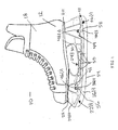
- FIG. 1 is a side view of a skate with an accessible runner securing system in accordance with embodiments of the present invention
- FIG. 2 is a top view of the skate shown in FIG. 1 ;
- FIG. 3 is a side, cross-sectional view of the skate shown in FIG. 1 ;
- FIG. 4 is an exploded, view of the skate shown in FIG. 1 ;
- FIG. 5 is a side, cross-sectional view of a skate with an accessible runner securing system in accordance with embodiments of the present invention
- FIG. 6 is an exploded, view of the skate shown in FIG. 5 ;
- FIG. 7 is a perspective view of a lug used in the accessible runner securing system shown in FIG. 5 .
- FIGS. 1-4 A skate 10 in accordance with embodiments of the present invention is illustrated in FIGS. 1-4 .
- the skate 10 includes a boot 12, a skate holder 14(1), and a runner 16(1), although the skate 10 can comprise other numbers and types of components in other configurations.
- the present invention provides an ice skate 10 in which the runner 16(1) of the ice skate can be easily attached to or removed from a skate holder 14(1).
- the boot 12 includes a shell 18 shaped to receive a foot and a sole 20 connected to the shell 18, although the boot 12 can comprise other numbers and types of components in other configurations.
- a boot and method for making a boot for a skate are described in U.S. Patent No. 6,295,679 , which is herein incorporated by reference. Since boots for skates are well known to those of ordinary skill in the art, they will not be described in further detail here.
- the holder 14(1) includes a front section 22(1), a bridge section 24(1), and a rear section 26(1), although the holder can comprise other numbers and types of components in other configurations and other types of holders can be used, such as 14(2) shown in FIGS. 5-6 .
- the bridge section 24(1) couples the front and rear sections 22(1) and 26(1) together and in this embodiment the front, bridge, and rear sections 22(1), 24(1), and 26(1) are integrally formed, although other configurations could be used.
- An upper portion 28 of the front section 22(1) is secured to a front portion of the sole 20 with rivets through openings 29 in portion 28 and an upper portion 30 of the rear section 26(1) is secured to a rear portion of the sole 20 with rivets through openings 31 in portion 30, although other attachment configurations and other devices to secure the holder 14(1) to the sole 20 can be used.
- a longitudinally extending groove 32 is formed along a lower portion of the front, bridge and rear sections 22(1), 24(1), and 26(1) of the holder 14(1) and is shaped to receive an upper portion of the runner 16(1).
- the front section 22(1) includes a pair of separated, hollow regions 21(1)-21(2) and an opening 42 positioned between the hollow regions 21(1)-21(2), although other configurations could be used, such as multiple hollow regions or openings or having an opening which only extends partially through the holder 14(1).
- the rear section 26(1) includes pair of separated, hollow regions 27(1)-27(2) and an opening 44 positioned between the hollow regions 27(1)-27(2), although other configurations could be used, such as multiple hollow regions or openings or having an opening which only extends partially through the holder 14(1).
- the hollow regions 21(1), 21(2), 27(1), and 27(2) in the holder 14(1) help to reduce the weight of the skate without negatively effecting the structural integrity and strength of the holder 14(1). As a result, with this skate holder 14(1) the skate 10 is noticeably lighter while still being durable.
- the openings 42 and 44 in the front and rear sections 22(1) and 26(1) provide access to nuts 46(1) and 48(1) which are used to secure the runner 16(1) to the holder 14(1) so that an individual can easily attach or remove and replace a runner 16(1) on a skate 10.
- the openings 42 and 44 are sized so that an individual can easily access the access the nuts 46(1) and 48(1) secured on the threaded attachment devices 36(1) and 40(1) with the individual's fingers or a tool. Accordingly, with the present invention, an individual wearing the skate 10 can easily secure or remove a runner 16(1) from holder 14(1), without having to remove the holder 14(1) from the boot 12 and without having to use the prior horizontal technique for securing a runner to a holder.
- the front section 22(1) has a passage 34(1) that extends through a wall 19(1) of the holder 14(1) which is positioned between the hollow regions 21(1)-21(2) and which is sized to receive one end of a threaded attachment device 36(1), such as a bolt
- the rear section 26(1) has a passage 38(1) that extends through a wall 33(1) of the holder 14(1) between the hollow regions 27(1)-27(2) and which is sized to receive one end of another threaded attachment device 40(1).
- the passages 34(1) and 38(1) extend in a substantially vertical direction, although other directions and configurations for the passages 34(1) and 38(1) can be used, such as having the passages extend at an angle.
- the holder 14(1) also includes the bridge section 24(1) which has a plurality of openings 50 extend.
- the openings 50 in the bridge section 24(1) also help to reduce the overall weight of the skate 10.
- the runner 16(1) includes an upper, elongated edge 52 which is dimensioned to fit within the groove 32 in the front, bridge, and rear sections 22(1), 24(1), and 26(1) of the holder 14(1) and a lower, elongated edge 54 which forms the skating edge for the skate 10.
- a pair of cavities 56 and 58 are formed in the upper elongated edge 52, although other numbers and types of mechanisms for securing one end of the attachment devices 36(1) and 40(1) to the runner 16(1) could be used, such as integrally forming the attachment devices with the runner 16(1).
- the cavity 56 is shaped to mate with one end of the threaded attachment device 36(1) and the cavity 58 is shaped to mate with one end of the threaded attachment device 40(1).
- one type of runner 16(1) is shown, other types of runners can be used.
- the threaded attachment devices 36(1) and 40(1) extend out away from the edge 52 of the runner 16(1).
- the threaded attachment device 36(1) has another threaded end that extends up through the passage 34(1) in the front section 22(1) to the opening 42.
- the threaded attachment device 40(1) has another threaded end that extends up through the passage 38(1) in the rear section 26(1) to the opening 44.
- a threaded nut 46(1) is rotationally seated on the thread end of the attachment device 36(1) and another nut 48(1) is seated on the threaded end of the attachment device 40(1).
- the nuts 46(1) and 48(1) are rotated on the threaded attachment devices 36(1) and 40(1) to secure the runner 16(1) to the holder 14(1) or to release the threaded attachment devices 36(1) and 40(1) so the runner 16(1) can be replaced.
- a method for securing a runner 16(1) to the holder 14(1) will now be described with reference to FIGS. 1-4 .
- One end of threaded attachment device is mated with the cavity 56 and one end of threaded attachment device 40(1) is mated with the cavity 58.
- the threaded attachment device 36(1) is passed through passage 34(1) and extends into the opening 42 in the front section 22(1) and threaded attachment device 40(1) is passed through passage 38(1) and extends into the opening 44 in the rear section 26(1).
- An upper edge 52 of the runner 16(1) is seated in the groove 32 in the front, bridge, and rear sections 22(1), 24(1), and 26(1) of the holder 14(1).
- a nut 46(1) is threaded on the threaded attachment device 36(1) and another nut 48(1) is threaded on the threaded attachment device 40(1), The nuts 46(1) and 48(1) are tightened on the threaded attachment devices 36(1) and 40(1) until the runner 16(1) is secure in the holder 14(1). To replace the runner 16(1), the nuts 46(1) and 48(1) are simply unscrewed from the threaded attachment devices 36(1) and 40(1) and the runner 16(1) is removed from the holder 14(1).
- FIGS. 5-7 an alternative embodiment for the holder 14(2) for the skate 10 is illustrated. Elements in the embodiment shown in FIGS. 5-7 which are like those in the embodiment shown in FIGS. 1-4 will have like reference numerals and will not be described again. For ease of illustration the boot 12 is not illustrated in this embodiment.
- the holder 14(2) is the same as the holder 14(1), except as described and illustrated herein.
- the holder 14(2) includes a front section 22(2), a bridge section 24(2), and a rear section 26(2) which couples the front and rear sections 22(2) and 26(2) together, although the holder can comprise other numbers and types of components in other configurations.
- the front section 22(2) includes a passage 34(2) that extends through a wall 19(2) of the holder 14(2) which is positioned between the hollow regions 21(1)-21(2) and which is sized to receive one end of an attachment device 36(2), such as a nail head.
- the rear section 26(2) includes a passage 38(2) that extends through a wall 33(2) of the holder 14(2) which is positioned between the hollow regions 27(1)-27(2) and which is sized to receive one end of another attachment device 40(2), such as a nail head.
- the passages 34(2) and 38(2) extend in a substantially vertical direction, although other configurations for the passages 34(2) and 38(2) can be used.
- attachment devices 36(2) and 40(2) With the vertical configuration for the attachment devices 36(2) and 40(2) through the passages 34(2) and 38(2), pressure on the edges of the runner 16(2) will not loosen the connection of the runner 16(2) to the holder 14(2). Additionally, with this configuration the strength of the holder 14(2) is maintained because attachment devices 36(2) and 40(2) extend through the walls 19(2) and 33(2) and not into and/or through any of the hollow regions 21(1), 21(2), 27(1), or 27(2) of the holder 14(2). As a result, the strength of the hollow regions 21(1), 21(2), 27(1), or 27(2) and thus of the holder 14(2) is not compromised by the attachment of the runner 16(2) to the holder 14(2).
- the front section 22(2) also includes a lug nut housing 23 positioned in the opening 42 for the lug nut 46(2) and the rear section 26(2) includes a lug nut housing 25 positioned in the opening 44 for the lug nut 48(2).
- the lug nut housing 23 has an opening to the passage 34(2) which is sized to receive the attachment device 36(2) and the lug nut housing 25 has an opening which is sized to receive the attachment device 40(2).
- the runner 16(2) is the same as the runner 16(1), except as described and illustrated herein.
- a pair of attachment devices 36(2) and 40(2) are secured to the upper edge 52 of the runner 16(2) with welds, although other manners for securing the attachment devices 36(2) and 40(2) to the runner 16(2) could be used.
- the lug nuts 46(2) and 48(2) each include a pair of outer rims 60(1) and 60(2) which are joined by a center section 62, although lug nuts 46(2) and 48(2) may each comprise other sections in other configurations. Since lug nut 48(2) is the same as lug nut 46(2), only lug nut 46(2) is described herein and shown in FIG. 7 .
- the center section 62 of each of the lug nuts 46(2) and 48(2) includes a passage 64 which is sized to fit over the nail head end of attachment devices 36(2) and 40(2).
- a channel 66 is formed in the center section 62 of each of the lug nuts 46(2) and 48(2) and extends partially around the center section.
- edges 68(1) and 68(2) of the center section 62 about the channel 66 in each of the lug nuts 46(2) and 48(2) are tapered and gradually increase in thickness towards the end of the channel 66.
- the end of the center section 62 after the end of the channel 66 in each of the lug nuts 46(2) and 48(2) has a substantially flat portion 70.
- Each of the lug nuts 46(2) and 48(2) includes a slot 72 to receive the head of a flat head screw driver or other tool to rotate the lug nuts 46(2) and 48(2), although other numbers and configurations for the slot as well as other manners for rotating the lug nuts 46(2) and 48(2) can be used.
- the lug nut 46(2) is designed to mate with one end of the attachment device 36(2) through the opening 64 and the lug nut 48(2) is designed to mate with one end of the attachment device 40(2) through the opening 64. If the lug nut 46(2) is rotated, the head of the attachment device 36(2) is sized to rest and ride on the edges 68(1) and 68(2) of center section 62 of lug nut 46(2). Similarly, if the lug nut 48(2) is rotated, the head of the attachment device 40(2) is sized to rest and ride on the edges 68(1) and 68(2) of center section 62 of lug nut 48(2). Although two attachment devices 36(2) and 40(2) are shown with lug nuts 46(2) and 48(2), other numbers and types of attachment devices and lug nuts can be used.
- a method for securing a runner 16(2) to the holder 14(2) shown in FIGS. 5-6 is the same as the method for securing the runner 16(2) to the holder 14(1) shown in FIGS. 1-4 except as described below.
- One end of the attachment device 36(2) is passed through passage 34(2) and through the opening 64 in the lug nut 46(2) into the lug nut housing 23 in opening 42 in the front section 22(1).
- One end of the attachment device 40(2) is passed through passage 38(2) and through the opening 64 in the lug nut 48(2) into the lug nut housing 23 in opening 44 in the rear section 26(1).
- An upper edge 52 of the runner 16(2) is seated in the groove 32 in the front, bridge, and rear sections 22(2), 24(2), and 26(2) of the holder 14(2).
- a flat head screw driver or other tool is seated in the slot 72 of the lug nut 46(2) and is rotated.
- Rotating the lug nut 46(2) seats the head of the attachment device 36(2) on the edges 68(1) and 68(2) of the lug nut 46(2).
- Continued rotation of the lug nut 46(2) causes the head of the attachment device 36(2) to ride up the edges 68(1) and 68(2) which pulls the runner 16(2) further up into the slot 32 to secure one end of the runner 16(2) against the holder 14(2).
- a flat head screw driver or other tool is seated in the slot 72 of the lug nut 48(2) and is rotated.
- Rotating the lug nut 48(2) seats the head of the attachment device 40(2) on the edges 68(1) and 68(2) of the lug nut 48(2).
- Continued rotation of the lug nut 48(2) causes the head of the attachment device 40(2) to ride up the edges 68(1) and 68(2) which pulls the runner 16(2) further up into the slot 32 to secure another end of the runner 16(2) against the holder 14(2).
Landscapes
- Footwear And Its Accessory, Manufacturing Method And Apparatuses (AREA)
- Knives (AREA)
Claims (14)
- Lame pour patin (10) comprenant :une console (14(1) ; 14(2)) comprenant une section avant (22 (1) ; 22(2)) et une section arrière (26 (1) ; 26(2)), où au moins l'une de la section avant et de la section arrière comprend au moins deux régions creuses séparées (21(1), 21(2), 27(1), 27(2)) et une ouverture (42, 44) qui s'étend à travers la console entre lesdites au moins deux régions creuses séparées et sépare lesdites au moins deux régions creuses séparées les unes des autres sur une longueur de la console ;une lame de glissement (16(1) ; 16(2)) ; etun dispositif de fixation (36(1), 46(1), 40(1), 48(1) ; 36(2), 46(2), 40(2), 48(2)) qui arrime la lame de glissement à la console,caractérisée en ce quele dispositif de fixation s'étend à travers un passage (34(1), 38(1) ; 34(2), 38(2)) situé dans une portion sensiblement pleine (19(1), 33(1) ; 19(2), 33(2)) de la console entre lesdites au moins deux régions creuses séparées et dans l'ouverture, où au moins une portion du dispositif de fixation utilisé pour arrimer la lame de glissement à la console est accessible dans l'ouverture.
- Lame selon la revendication 1, dans laquelle le dispositif de fixation comprend un boulon fileté (36(1), 40(1)) et un écrou fileté (46(1), 48(1)), le boulon fileté est fixé à une extrémité à la lame de glissement et l'écrou fileté est assis en rotation sur le boulon fileté pour arrimer la lame de glissement à la console, où l'écrou fileté est accessible dans l'ouverture.
- Lame selon la revendication 1, dans laquelle le dispositif de fixation comprend une tige (36(2), 40(2)) avec une portion de tête et un écrou conique (46(2), 48(2)), la tige est fixée à une extrémité à la lame de glissement et l'écrou conique est assis en rotation sur la portion de tête de la tige pour arrimer la lame de glissement à la console, où l'écrou conique est accessible dans l'ouverture.
- Lame selon la revendication 1, dans laquelle l'autre de l'une parmi la section avant et la section arrière (22(1), 26(1) ; 22(2), 26(2)) comprend au moins deux autres régions creuses séparées (21(1), 21(2), 27(1), 27(2)) et une autre ouverture (42, 44) qui s'étend à travers la console entre lesdites au moins deux autres régions creuses séparées et sépare lesdites au moins deux autres régions creuses séparées les unes des autres suivant une longueur de la console, la lame comprenant en outre un autre dispositif de fixation qui s'étend à travers un autre passage (34(1), 38(1) ; 34(2), 38(2)) situé dans une autre portion sensiblement pleine (19(1), 33(1) ; 19(2), 33(2)) de la console entre lesdites au moins deux autres régions creuses séparées et dans l'autre ouverture, où l'autre dispositif de fixation arrime la lame de glissement à la console et où au moins une portion de l'autre dispositif de fixation utilisé pour arrimer la lame de glissement à la console est accessible dans l'ouverture.
- Lame selon la revendication 4, comprenant en outre une section de pont (24(1) ; 24(2)) entre la section avant et la section arrière.
- Lame selon la revendication 5, comprenant en outre une pluralité d'ouvertures (50) dans la section de pont.
- Procédé pour arrimer une lame de glissement de patin à une console, le procédé comprenant les étapes consistant à :fournir une console (14(1) ; 14(2)) comprenant une section avant (22(1) ; 22(2)) et une section arrière (26(1) ; 26(2)), où au moins l'une de la section avant et de la section arrière comprend au moins deux régions creuses séparées (21(1), 21(2), 27(1), 27(2)) et une ouverture (42, 44) qui s'étend à travers la console entre lesdites au moins deux régions creuses séparées et sépare lesdites au moins deux régions creuses séparées les unes des autres suivant une longueur de la console ;positionner un bord (52) d'une lame de glissement (16(1) ; 16(2)) contre une portion de la console ;caractérisé par l'étape consistant àétendre un dispositif de fixation (36(1), 46(1), 40(1), 48(1) ; 36(2), 46(2), 40(2), 48(2)) à travers un passage (34(1), 38(1) ; 34(2), 38(2)) situé dans une portion sensiblement pleine (19(1), 33(1) ; 19(2), 33(2)) de la console entre lesdites au moins deux régions creuses séparées et dans l'ouverture, où le dispositif de fixation arrime la lame de glissement à la console et où au moins une portion du dispositif de fixation utilisé pour arrimer la lame de glissement à la console est accessible dans l'ouverture.
- Procédé selon la revendication 7, dans lequel le dispositif de fixation comprend un boulon fileté (36(1), 40(1)) et un écrou fileté (46(1), 48(1)), le boulon fileté est fixé à une extrémité à la lame de glissement et l'écrou fileté est assis en rotation sur le boulon fileté pour arrimer la lame de glissement à la console, où l'écrou fileté est accessible dans l'ouverture.
- Procédé selon la revendication 7, dans lequel le dispositif de fixation comprend une tige (36(2), 40(2)) avec une portion de tête et un écrou conique (46(2), 48(2)), la tige est fixée à une extrémité à la lame de glissement et l'écrou conique est assis en rotation sur la portion de tête de la tige pour arrimer la lame de glissement à la console, où l'écrou conique est accessible dans l'ouverture.
- Procédé selon la revendication 7, dans lequel l'autre de l'une parmi la section avant et la section arrière (22(1), 26(1) ; 22(2), 26(2)) comprend au moins deux autres régions creuses séparées (21(1), 21(2), 27(1), 27(2)) et une autre ouverture (42, 44) qui s'étend à travers la console entre lesdites au moins deux autres régions creuses séparées et sépare lesdites au moins deux autres régions creuses séparées les unes des autres suivant une longueur de la console, le procédé comprenant en outre l'étape consistant à étendre un autre dispositif de fixation à travers un autre passage (34(1), 38(1) ; 34(2), 38(2)) situé dans une autre portion sensiblement pleine (19(1), 33(1) ; 19(2), 33(2)) de la console entre lesdites au moins deux autres régions creuses séparées et dans l'autre ouverture, où l'autre dispositif de fixation arrime la lame de glissement à la console et où au moins une portion de l'autre dispositif de fixation utilisé pour arrimer la lame de glissement à la console est accessible dans l'ouverture.
- Procédé selon la revendication 10, comprenant en outre l'étape consistant à fournir une section de pont (24(1) ; 24(2)) entre la section avant et la section arrière.
- Procédé selon la revendication 11, comprenant en outre une pluralité d'ouvertures (50) dans la section de pont.
- Procédé selon l'une quelconque des revendications 7 à 12, dans lequel la console est arrimée à une bottine (12) d'un patin (10).
- Patin (10) comprenant :une bottine (12) ; etune lame telle que précisée dans l'une quelconque des revendications 1 à 6.
Applications Claiming Priority (2)
| Application Number | Priority Date | Filing Date | Title |
|---|---|---|---|
| US54129304P | 2004-02-03 | 2004-02-03 | |
| PCT/US2004/042526 WO2005079215A2 (fr) | 2004-02-03 | 2004-12-17 | Lame muni d'un systeme accessible de fixation de lame et procedes associes |
Publications (3)
| Publication Number | Publication Date |
|---|---|
| EP1742713A2 EP1742713A2 (fr) | 2007-01-17 |
| EP1742713A4 EP1742713A4 (fr) | 2010-03-17 |
| EP1742713B1 true EP1742713B1 (fr) | 2013-01-23 |
Family
ID=34885953
Family Applications (1)
| Application Number | Title | Priority Date | Filing Date |
|---|---|---|---|
| EP04814677A Expired - Lifetime EP1742713B1 (fr) | 2004-02-03 | 2004-12-17 | Lame muni d'un systeme accessible de fixation de lame et procedes associes |
Country Status (4)
| Country | Link |
|---|---|
| US (2) | US8297627B2 (fr) |
| EP (1) | EP1742713B1 (fr) |
| CA (1) | CA2556170C (fr) |
| WO (1) | WO2005079215A2 (fr) |
Families Citing this family (21)
| Publication number | Priority date | Publication date | Assignee | Title |
|---|---|---|---|---|
| CA2487626C (fr) * | 2004-11-12 | 2013-01-15 | Dahlo, Alan Larry | Patin a glace et sa lame |
| US20090206562A1 (en) * | 2005-08-18 | 2009-08-20 | Anatol Podolsky | Skate blades and methods and apparatus for affixing same |
| EP2326395B1 (fr) * | 2008-07-25 | 2019-09-04 | Multimatic Inc. | Verrou rotatif de retenue pour systèmes de lames remplaçables de patins |
| EP2777781A1 (fr) | 2013-03-14 | 2014-09-17 | Bauer Hockey Corp. | Patin à glace |
| USD762275S1 (en) * | 2014-03-14 | 2016-07-26 | Bauer Hockey, Inc. | Ice skate blade holder |
| CA2909496C (fr) | 2014-10-22 | 2020-07-07 | Easton Hockey, Inc. | Patin de hockey comportant un cadre monopiece dote de supports integraux |
| US10406424B2 (en) | 2015-01-05 | 2019-09-10 | Bauer Hockey, Llc | Ice skate |
| USD806194S1 (en) * | 2015-12-23 | 2017-12-26 | Bauer Hockey, Llc | Blade holder for an ice skate |
| WO2017136942A1 (fr) | 2016-02-09 | 2017-08-17 | Bauer Hockey Corp. | Patin ou autres chaussures |
| US9855487B2 (en) * | 2016-03-08 | 2018-01-02 | Sport Maska Inc. | Blade holder assembly |
| US10376771B2 (en) | 2016-06-30 | 2019-08-13 | Bauer Hockey, Llc | Ice skate |
| USD949273S1 (en) | 2016-10-26 | 2022-04-19 | Bauer Hockey Llc. | Ice skate blade holder |
| US10974123B2 (en) * | 2016-12-22 | 2021-04-13 | Bauer Hockey Llc | Ice skate blade |
| US11071903B2 (en) * | 2016-12-22 | 2021-07-27 | Bauer Hockey Llc | Ice skate blade |
| USD835740S1 (en) | 2017-03-16 | 2018-12-11 | Sport Maska Inc. | Runner for ice skate |
| WO2019218070A1 (fr) * | 2018-05-16 | 2019-11-21 | Sport Maska Inc. | Porte-lame de patin à mécanisme de fixation de lame |
| US12349765B2 (en) | 2018-10-29 | 2025-07-08 | Bauer Hockey Llc | Skate or other footwear |
| CA3089463A1 (fr) * | 2020-08-05 | 2022-02-05 | Kelly Riou | Patin et lame de patin d'entrainement hors glace |
| USD992649S1 (en) * | 2021-06-15 | 2023-07-18 | G20 holding SA | Skate assembly for scooter |
| US12403384B2 (en) | 2022-06-21 | 2025-09-02 | Sport Maska Inc. | Skate blade holder with blade attachment mechanism and blade therefor |
| CH721377A2 (de) * | 2023-12-08 | 2025-06-13 | Alexander Kaelin | Schlittschuhkufenanordnung |
Family Cites Families (55)
| Publication number | Priority date | Publication date | Assignee | Title |
|---|---|---|---|---|
| CA585720A (fr) | 1959-10-27 | E. Kirkpatrick John | Patin a glace | |
| US235494A (en) * | 1880-12-14 | Chaeles behlen | ||
| CA41809A (fr) | 1893-02-04 | Walker, Thomas B. | Machine a compter | |
| US1749298A (en) * | 1928-11-26 | 1930-03-04 | Maximilian J Orafsik | Ice skate |
| US2874970A (en) * | 1957-05-31 | 1959-02-24 | Willis B Mall | Convertible skates |
| NL287687A (fr) * | 1962-01-12 | |||
| CA984422A (en) | 1974-05-07 | 1976-02-24 | Kenbudge Holdings Limited | Ice skate |
| CA989436A (en) | 1975-10-02 | 1976-05-18 | Kenbudge Holdings Limited | Ice skate |
| CA1072994A (fr) | 1976-08-12 | 1980-03-04 | Kenbudge Holdings Limited | Patins a glace a lames jetables dans un support en plastique |
| US4074909A (en) * | 1976-08-18 | 1978-02-21 | Kenbudge Holdings Limited | Ice skate |
| USD250490S (en) * | 1976-09-27 | 1978-12-05 | Kenbudge Holdings Limited | Ice skate |
| US4139209A (en) * | 1977-12-08 | 1979-02-13 | Humphreys Donald R | Adjustable shoe-skate assembly |
| CA1088968A (fr) | 1978-01-20 | 1980-11-04 | Pfz Enterprises Inc. | Support en matiere plastique pour lame de patin, avec cavites pour assurer le positionnement de la lame |
| CA1113129A (fr) | 1978-07-21 | 1981-11-24 | Tuuk Sports Ltd. | Fabrication de patins |
| CA1105510A (fr) | 1979-07-13 | 1981-07-21 | St. Lawrence Manufacturing Company Inc. | Lame de patin |
| US4282659A (en) | 1979-08-21 | 1981-08-11 | Gamebridge, Inc. | Sports boot strap closure system |
| USD271036S (en) * | 1980-01-18 | 1983-10-18 | Canpro Sport Inc. | Skate |
| USD268125S (en) | 1980-01-18 | 1983-03-01 | Canpro Sport Inc. | Skate |
| CS214112B1 (en) * | 1980-05-08 | 1982-04-09 | Ivan Mazak | Skate |
| USD267125S (en) * | 1980-05-05 | 1982-11-30 | Luoma Harold E | Drain board |
| US4351536A (en) * | 1980-08-15 | 1982-09-28 | Sandino Hector M | Ice skate attachment |
| CA1213916A (fr) | 1983-02-10 | 1986-11-12 | Rosaire Landry | Lame interchangeable pour patin |
| CA1225672A (fr) | 1984-10-01 | 1987-08-18 | Icaro Olivieri | Patin a glace |
| US4932675A (en) | 1986-11-28 | 1990-06-12 | Scott B. Olson | Skate assembly |
| NL193856C (nl) * | 1988-10-11 | 2001-01-03 | Wintersport Leerdam B V | Noorse schaats. |
| CA1314913C (fr) | 1989-02-24 | 1993-03-23 | Brian Gregory Cann | Lame de patin a glace |
| USD325416S (en) * | 1990-04-11 | 1992-04-14 | Scott B. Olson | Ice skate |
| US5152083A (en) | 1991-02-12 | 1992-10-06 | A. Lambert International Inc. | Air pumping assembly for an ice skate pressurized boot |
| CA2036477C (fr) | 1991-02-15 | 1995-05-23 | Brian Gregory Cann | Patin a glace a lame amovible |
| DE4127294C1 (en) | 1991-07-12 | 1992-11-26 | Holger 7730 Villingen-Schwenningen De Wuerthner | Sports skate shoe - has ends of profiled slide strip fixed to runner and held under tension |
| DE4233880C1 (de) * | 1992-10-08 | 1994-01-05 | Holger Wuerthner | Kufensportgerät oder Kufenfahrzeug mit auswechselbarem Laufmesser |
| CA2084958A1 (fr) | 1992-12-09 | 1994-06-10 | Rudi Scherz | Patin a glace |
| SE9304036D0 (sv) | 1993-12-03 | 1993-12-03 | Oerebroskenan Ab | Skridskoskena |
| IT233563Y1 (it) | 1994-06-03 | 2000-02-01 | Htm Sport Spa | Pattino provvisto di scarpetta regolabile rispetto all'attrezzo. |
| CA2199391C (fr) | 1994-06-14 | 2007-10-16 | Icaro Olivieri | Lame de patin a glace et assemblage de lame |
| US5484148A (en) * | 1994-06-14 | 1996-01-16 | Canstar Sports Group Inc. | Skate blade assembly with reinforcement insert |
| US6164667A (en) * | 1994-06-14 | 2000-12-26 | Bauer Nike Hockey Inc. | Skate blade and skate blade assembly |
| US5641169A (en) * | 1994-10-21 | 1997-06-24 | Bekessy; George J. | Quick release ice skate blade assembly |
| DE19503792C2 (de) | 1995-02-06 | 1996-12-05 | Rudolf Linner | Schlittschuh- bzw. Rollschuhstiefel, insbesondere für Eis- bzw. Rollhockey |
| CA2243095A1 (fr) | 1997-07-11 | 1999-01-11 | Almanac Marketing Services Ltd. | Ensemble de lame de patin a glace |
| IT1294789B1 (it) * | 1997-07-15 | 1999-04-15 | Bauer Italia Spa | Pattino da ghiaccio a lama intercambiabile |
| USD414017S (en) * | 1997-09-05 | 1999-09-21 | Bauer, Inc. | Skate boot upper |
| US6109622A (en) | 1998-03-20 | 2000-08-29 | Mission Hockey Company | Ice skate chassis and blade holder assembly |
| USD430251S (en) * | 1998-08-21 | 2000-08-29 | Graf Skates Ag | Runner fixture |
| US6467778B1 (en) | 1998-09-16 | 2002-10-22 | Jas D. Easton, Inc. | Ice skate |
| US6419241B1 (en) * | 1998-12-22 | 2002-07-16 | Bauer Nike Hockey Inc. | Ice skate runner |
| CA2256917A1 (fr) * | 1998-12-22 | 2000-06-22 | Bauer Nike Hockey Inc. | Article chaussant |
| US6932361B2 (en) * | 2000-06-26 | 2005-08-23 | Paul M. Steinhauser, Jr. | Skate with removable blade |
| USD475205S1 (en) * | 2001-09-17 | 2003-06-03 | Bauer Nike Hockey Inc. | Ice skate blade |
| CA2388935C (fr) | 2001-10-18 | 2009-11-10 | Stephane Bussiere | Chaussure a systeme de retenue du pied |
| USD488845S1 (en) * | 2002-04-26 | 2004-04-20 | Bauer Nike Hockey, Inc. | Ice skate blade holder |
| ATE509758T1 (de) | 2003-09-10 | 2011-06-15 | Easton James D Inc | Schuhwerkartikel mit einer einteiligen stützkonstruktion und herstellungsverfahren |
| US7036828B1 (en) * | 2004-10-15 | 2006-05-02 | Tournament Sports Marketing Inc. | Extruded light-weight figure skate blade holder with two part blade |
| CA2487626C (fr) | 2004-11-12 | 2013-01-15 | Dahlo, Alan Larry | Patin a glace et sa lame |
| CA2500086A1 (fr) | 2005-03-09 | 2005-12-18 | Hal N. Merritt | Courroie liberable resistant au glissement |
-
2004
- 2004-12-17 EP EP04814677A patent/EP1742713B1/fr not_active Expired - Lifetime
- 2004-12-17 WO PCT/US2004/042526 patent/WO2005079215A2/fr not_active Ceased
- 2004-12-17 US US11/016,416 patent/US8297627B2/en not_active Expired - Fee Related
- 2004-12-17 CA CA2556170A patent/CA2556170C/fr not_active Expired - Fee Related
-
2007
- 2007-10-05 US US11/867,991 patent/US7628405B2/en not_active Expired - Fee Related
Also Published As
| Publication number | Publication date |
|---|---|
| WO2005079215A3 (fr) | 2009-03-26 |
| EP1742713A2 (fr) | 2007-01-17 |
| US20050167934A1 (en) | 2005-08-04 |
| US20080191431A1 (en) | 2008-08-14 |
| US8297627B2 (en) | 2012-10-30 |
| CA2556170C (fr) | 2012-05-29 |
| US7628405B2 (en) | 2009-12-08 |
| EP1742713A4 (fr) | 2010-03-17 |
| CA2556170A1 (fr) | 2005-09-01 |
| WO2005079215A2 (fr) | 2005-09-01 |
Similar Documents
| Publication | Publication Date | Title |
|---|---|---|
| US7628405B2 (en) | Skate with an accessible runner securing system and methods thereof | |
| USRE44805E1 (en) | Ice skate and ice skate blade thereof | |
| EP0428584B1 (fr) | Patin | |
| US5213009A (en) | Cleat for clipless pedals | |
| US20020190487A1 (en) | Goalie skate protective shell with removable blade | |
| US5662338A (en) | Skate with lateral torque support members | |
| EP2369950B1 (fr) | Étalon de montage de semelle de chaussure pour cale de vélo | |
| US7926849B2 (en) | Ski pole basket comprising an adjustable supporting surface | |
| US6481724B1 (en) | Adapter for converting in-line roller skates to ice skates | |
| US4669752A (en) | Cross country ski pole with interchangeable baskets | |
| US9433851B2 (en) | Double-edged skate blade assembly and holder | |
| US6065758A (en) | Skate | |
| US20070218788A1 (en) | Fin attachment system and method | |
| WO2005021363A2 (fr) | Ensemble selle de bicyclette | |
| US5735536A (en) | Skate and skate chassis and method of making and using the same | |
| CA2727804C (fr) | Mecanisme de verrouillage pour lame de patin a glace | |
| US6003882A (en) | Customizable skate with removable wheel hangers | |
| US7036828B1 (en) | Extruded light-weight figure skate blade holder with two part blade | |
| US3243191A (en) | Adjustable ice skate | |
| EP1924333B1 (fr) | Lames de patin et procédés et appareil de fixation | |
| CA2397000C (fr) | Enveloppe de protection de patin de gardien de but a lame amovible | |
| AU2006101078A5 (en) | Fin Attachment System | |
| CA3214836A1 (fr) | Remplacement de rivets de patins | |
| EP0652034A1 (fr) | Patin à roulettes alignées | |
| US20150321074A1 (en) | Binding system and method with interchangeable frames having sporting blades or rollers thereon |
Legal Events
| Date | Code | Title | Description |
|---|---|---|---|
| PUAI | Public reference made under article 153(3) epc to a published international application that has entered the european phase |
Free format text: ORIGINAL CODE: 0009012 |
|
| 17P | Request for examination filed |
Effective date: 20060901 |
|
| AK | Designated contracting states |
Kind code of ref document: A2 Designated state(s): AT BE BG CH CY CZ DE DK EE ES FI FR GB GR HU IE IS IT LI LT LU MC NL PL PT RO SE SI SK TR |
|
| AX | Request for extension of the european patent |
Extension state: AL BA HR LV MK YU |
|
| DAX | Request for extension of the european patent (deleted) | ||
| PUAK | Availability of information related to the publication of the international search report |
Free format text: ORIGINAL CODE: 0009015 |
|
| RIC1 | Information provided on ipc code assigned before grant |
Ipc: A63C 1/30 20060101AFI20090430BHEP |
|
| A4 | Supplementary search report drawn up and despatched |
Effective date: 20100212 |
|
| 17Q | First examination report despatched |
Effective date: 20110311 |
|
| REG | Reference to a national code |
Ref country code: DE Ref legal event code: R079 Ref document number: 602004040885 Country of ref document: DE Free format text: PREVIOUS MAIN CLASS: A63C0001000000 Ipc: A63C0001320000 |
|
| RIC1 | Information provided on ipc code assigned before grant |
Ipc: A63C 1/32 20060101AFI20120613BHEP Ipc: A63C 1/30 20060101ALI20120613BHEP |
|
| GRAP | Despatch of communication of intention to grant a patent |
Free format text: ORIGINAL CODE: EPIDOSNIGR1 |
|
| GRAS | Grant fee paid |
Free format text: ORIGINAL CODE: EPIDOSNIGR3 |
|
| GRAA | (expected) grant |
Free format text: ORIGINAL CODE: 0009210 |
|
| AK | Designated contracting states |
Kind code of ref document: B1 Designated state(s): AT BE BG CH CY CZ DE DK EE ES FI FR GB GR HU IE IS IT LI LT LU MC NL PL PT RO SE SI SK TR |
|
| REG | Reference to a national code |
Ref country code: GB Ref legal event code: FG4D |
|
| REG | Reference to a national code |
Ref country code: CH Ref legal event code: EP |
|
| REG | Reference to a national code |
Ref country code: CH Ref legal event code: EP Ref country code: AT Ref legal event code: REF Ref document number: 594639 Country of ref document: AT Kind code of ref document: T Effective date: 20130215 |
|
| REG | Reference to a national code |
Ref country code: IE Ref legal event code: FG4D |
|
| REG | Reference to a national code |
Ref country code: DE Ref legal event code: R096 Ref document number: 602004040885 Country of ref document: DE Effective date: 20130321 |
|
| REG | Reference to a national code |
Ref country code: SE Ref legal event code: TRGR |
|
| REG | Reference to a national code |
Ref country code: AT Ref legal event code: MK05 Ref document number: 594639 Country of ref document: AT Kind code of ref document: T Effective date: 20130123 |
|
| REG | Reference to a national code |
Ref country code: LT Ref legal event code: MG4D |
|
| REG | Reference to a national code |
Ref country code: NL Ref legal event code: VDEP Effective date: 20130123 |
|
| PG25 | Lapsed in a contracting state [announced via postgrant information from national office to epo] |
Ref country code: IS Free format text: LAPSE BECAUSE OF FAILURE TO SUBMIT A TRANSLATION OF THE DESCRIPTION OR TO PAY THE FEE WITHIN THE PRESCRIBED TIME-LIMIT Effective date: 20130523 Ref country code: BG Free format text: LAPSE BECAUSE OF FAILURE TO SUBMIT A TRANSLATION OF THE DESCRIPTION OR TO PAY THE FEE WITHIN THE PRESCRIBED TIME-LIMIT Effective date: 20130423 Ref country code: LT Free format text: LAPSE BECAUSE OF FAILURE TO SUBMIT A TRANSLATION OF THE DESCRIPTION OR TO PAY THE FEE WITHIN THE PRESCRIBED TIME-LIMIT Effective date: 20130123 Ref country code: BE Free format text: LAPSE BECAUSE OF FAILURE TO SUBMIT A TRANSLATION OF THE DESCRIPTION OR TO PAY THE FEE WITHIN THE PRESCRIBED TIME-LIMIT Effective date: 20130123 Ref country code: ES Free format text: LAPSE BECAUSE OF FAILURE TO SUBMIT A TRANSLATION OF THE DESCRIPTION OR TO PAY THE FEE WITHIN THE PRESCRIBED TIME-LIMIT Effective date: 20130504 Ref country code: AT Free format text: LAPSE BECAUSE OF FAILURE TO SUBMIT A TRANSLATION OF THE DESCRIPTION OR TO PAY THE FEE WITHIN THE PRESCRIBED TIME-LIMIT Effective date: 20130123 |
|
| PG25 | Lapsed in a contracting state [announced via postgrant information from national office to epo] |
Ref country code: GR Free format text: LAPSE BECAUSE OF FAILURE TO SUBMIT A TRANSLATION OF THE DESCRIPTION OR TO PAY THE FEE WITHIN THE PRESCRIBED TIME-LIMIT Effective date: 20130424 Ref country code: PT Free format text: LAPSE BECAUSE OF FAILURE TO SUBMIT A TRANSLATION OF THE DESCRIPTION OR TO PAY THE FEE WITHIN THE PRESCRIBED TIME-LIMIT Effective date: 20130523 Ref country code: PL Free format text: LAPSE BECAUSE OF FAILURE TO SUBMIT A TRANSLATION OF THE DESCRIPTION OR TO PAY THE FEE WITHIN THE PRESCRIBED TIME-LIMIT Effective date: 20130123 Ref country code: SI Free format text: LAPSE BECAUSE OF FAILURE TO SUBMIT A TRANSLATION OF THE DESCRIPTION OR TO PAY THE FEE WITHIN THE PRESCRIBED TIME-LIMIT Effective date: 20130123 Ref country code: NL Free format text: LAPSE BECAUSE OF FAILURE TO SUBMIT A TRANSLATION OF THE DESCRIPTION OR TO PAY THE FEE WITHIN THE PRESCRIBED TIME-LIMIT Effective date: 20130123 |
|
| PG25 | Lapsed in a contracting state [announced via postgrant information from national office to epo] |
Ref country code: CZ Free format text: LAPSE BECAUSE OF FAILURE TO SUBMIT A TRANSLATION OF THE DESCRIPTION OR TO PAY THE FEE WITHIN THE PRESCRIBED TIME-LIMIT Effective date: 20130123 Ref country code: RO Free format text: LAPSE BECAUSE OF FAILURE TO SUBMIT A TRANSLATION OF THE DESCRIPTION OR TO PAY THE FEE WITHIN THE PRESCRIBED TIME-LIMIT Effective date: 20130123 Ref country code: EE Free format text: LAPSE BECAUSE OF FAILURE TO SUBMIT A TRANSLATION OF THE DESCRIPTION OR TO PAY THE FEE WITHIN THE PRESCRIBED TIME-LIMIT Effective date: 20130123 Ref country code: DK Free format text: LAPSE BECAUSE OF FAILURE TO SUBMIT A TRANSLATION OF THE DESCRIPTION OR TO PAY THE FEE WITHIN THE PRESCRIBED TIME-LIMIT Effective date: 20130123 Ref country code: SK Free format text: LAPSE BECAUSE OF FAILURE TO SUBMIT A TRANSLATION OF THE DESCRIPTION OR TO PAY THE FEE WITHIN THE PRESCRIBED TIME-LIMIT Effective date: 20130123 |
|
| PG25 | Lapsed in a contracting state [announced via postgrant information from national office to epo] |
Ref country code: CY Free format text: LAPSE BECAUSE OF FAILURE TO SUBMIT A TRANSLATION OF THE DESCRIPTION OR TO PAY THE FEE WITHIN THE PRESCRIBED TIME-LIMIT Effective date: 20130123 |
|
| PLBE | No opposition filed within time limit |
Free format text: ORIGINAL CODE: 0009261 |
|
| STAA | Information on the status of an ep patent application or granted ep patent |
Free format text: STATUS: NO OPPOSITION FILED WITHIN TIME LIMIT |
|
| PG25 | Lapsed in a contracting state [announced via postgrant information from national office to epo] |
Ref country code: IT Free format text: LAPSE BECAUSE OF FAILURE TO SUBMIT A TRANSLATION OF THE DESCRIPTION OR TO PAY THE FEE WITHIN THE PRESCRIBED TIME-LIMIT Effective date: 20130123 |
|
| 26N | No opposition filed |
Effective date: 20131024 |
|
| REG | Reference to a national code |
Ref country code: DE Ref legal event code: R097 Ref document number: 602004040885 Country of ref document: DE Effective date: 20131024 |
|
| PG25 | Lapsed in a contracting state [announced via postgrant information from national office to epo] |
Ref country code: MC Free format text: LAPSE BECAUSE OF FAILURE TO SUBMIT A TRANSLATION OF THE DESCRIPTION OR TO PAY THE FEE WITHIN THE PRESCRIBED TIME-LIMIT Effective date: 20130123 |
|
| REG | Reference to a national code |
Ref country code: CH Ref legal event code: PL |
|
| GBPC | Gb: european patent ceased through non-payment of renewal fee |
Effective date: 20131217 |
|
| PG25 | Lapsed in a contracting state [announced via postgrant information from national office to epo] |
Ref country code: LU Free format text: LAPSE BECAUSE OF FAILURE TO SUBMIT A TRANSLATION OF THE DESCRIPTION OR TO PAY THE FEE WITHIN THE PRESCRIBED TIME-LIMIT Effective date: 20131217 |
|
| REG | Reference to a national code |
Ref country code: IE Ref legal event code: MM4A |
|
| REG | Reference to a national code |
Ref country code: FR Ref legal event code: ST Effective date: 20140829 |
|
| PG25 | Lapsed in a contracting state [announced via postgrant information from national office to epo] |
Ref country code: CH Free format text: LAPSE BECAUSE OF NON-PAYMENT OF DUE FEES Effective date: 20131231 Ref country code: LI Free format text: LAPSE BECAUSE OF NON-PAYMENT OF DUE FEES Effective date: 20131231 Ref country code: IE Free format text: LAPSE BECAUSE OF NON-PAYMENT OF DUE FEES Effective date: 20131217 |
|
| PG25 | Lapsed in a contracting state [announced via postgrant information from national office to epo] |
Ref country code: FR Free format text: LAPSE BECAUSE OF NON-PAYMENT OF DUE FEES Effective date: 20131231 Ref country code: GB Free format text: LAPSE BECAUSE OF NON-PAYMENT OF DUE FEES Effective date: 20131217 |
|
| PGFP | Annual fee paid to national office [announced via postgrant information from national office to epo] |
Ref country code: SE Payment date: 20141211 Year of fee payment: 11 Ref country code: FI Payment date: 20141209 Year of fee payment: 11 Ref country code: DE Payment date: 20141209 Year of fee payment: 11 |
|
| PG25 | Lapsed in a contracting state [announced via postgrant information from national office to epo] |
Ref country code: TR Free format text: LAPSE BECAUSE OF FAILURE TO SUBMIT A TRANSLATION OF THE DESCRIPTION OR TO PAY THE FEE WITHIN THE PRESCRIBED TIME-LIMIT Effective date: 20130123 |
|
| PG25 | Lapsed in a contracting state [announced via postgrant information from national office to epo] |
Ref country code: HU Free format text: LAPSE BECAUSE OF FAILURE TO SUBMIT A TRANSLATION OF THE DESCRIPTION OR TO PAY THE FEE WITHIN THE PRESCRIBED TIME-LIMIT; INVALID AB INITIO Effective date: 20041217 |
|
| REG | Reference to a national code |
Ref country code: DE Ref legal event code: R119 Ref document number: 602004040885 Country of ref document: DE |
|
| REG | Reference to a national code |
Ref country code: SE Ref legal event code: EUG |
|
| PG25 | Lapsed in a contracting state [announced via postgrant information from national office to epo] |
Ref country code: SE Free format text: LAPSE BECAUSE OF NON-PAYMENT OF DUE FEES Effective date: 20151218 |
|
| PG25 | Lapsed in a contracting state [announced via postgrant information from national office to epo] |
Ref country code: DE Free format text: LAPSE BECAUSE OF NON-PAYMENT OF DUE FEES Effective date: 20160701 |
|
| PG25 | Lapsed in a contracting state [announced via postgrant information from national office to epo] |
Ref country code: FI Free format text: LAPSE BECAUSE OF NON-PAYMENT OF DUE FEES Effective date: 20151217 |