EP1743967A2 - Unité de contrôle pour dispositif de freinage de fil dans des fournisseurs de trame pour métiers à tisser et procédé de réglage associé - Google Patents
Unité de contrôle pour dispositif de freinage de fil dans des fournisseurs de trame pour métiers à tisser et procédé de réglage associé Download PDFInfo
- Publication number
- EP1743967A2 EP1743967A2 EP06009711A EP06009711A EP1743967A2 EP 1743967 A2 EP1743967 A2 EP 1743967A2 EP 06009711 A EP06009711 A EP 06009711A EP 06009711 A EP06009711 A EP 06009711A EP 1743967 A2 EP1743967 A2 EP 1743967A2
- Authority
- EP
- European Patent Office
- Prior art keywords
- actuator
- current
- measuring
- elastic constant
- control unit
- Prior art date
- Legal status (The legal status is an assumption and is not a legal conclusion. Google has not performed a legal analysis and makes no representation as to the accuracy of the status listed.)
- Granted
Links
Images


Classifications
-
- D—TEXTILES; PAPER
- D03—WEAVING
- D03D—WOVEN FABRICS; METHODS OF WEAVING; LOOMS
- D03D47/00—Looms in which bulk supply of weft does not pass through shed, e.g. shuttleless looms, gripper shuttle looms, dummy shuttle looms
- D03D47/34—Handling the weft between bulk storage and weft-inserting means
- D03D47/36—Measuring and cutting the weft
- D03D47/361—Drum-type weft feeding devices
- D03D47/364—Yarn braking means acting on the drum
- D03D47/366—Conical
Definitions
- the present invention relates to a control unit for yarn-braking devices in weft feeders for looms, in particular, rapier looms, projectile looms and airjet looms, and to a tuning method therefor.
- weft feeders for textile machines comprise a stationary drum on which a plurality of yarn loops forming a weft reserve are wound. Upon request from the loom, the loops are unwound from the drum, then pass through a braking device which controls the tension of the yarn, and finally are fed the loom.
- the braking device typically comprises a frustoconical hollow member which is supported at the centre of an annular support on a spider assembly of springs, and is biased with its inner surface against the end of the drum from which the loops are unwound.
- a pair of linear actuators operatively connected to the annular support are driven by a control unit having a position control loop and a current control loop, which is capable of generating a modulated current as a function of the fluctuations of the yam tension, in order to modulate the pressure applied upon the drum by the cone.
- This assembly is supported on a slide that is longitudinally movable under control of a worm screw mechanism that is manually operable in order to adjust the static pressure, or preload, applied upon the drum by the cone at rest. Therefore, the unwinding yarn runs between the drum and the frustoconical member, which modulately applies the desired braking action upon the yarn.
- the above control unit allows the braking action to be modulated smoothly and dynamically, however it has the drawback that its accuracy considerably decreases when certain parameters are changed, such as the stiffness of the springs which support the frustoconical member, or the static pressure applied upon the drum by the cone, which parameters are chosen, e.g., on the basis of the type of yam under processing, the loom speed, the loom height, and the like.
- the position control loop is designed to operate accurately with a specific set of springs and with a predetermined value of preload. On the contrary, changing these parameters results in an error of compensation. The more said parameters differ from the design parameters, the more rilevant said error.
- control unit for yarn-braking devices in weft feeders for looms which can be tuned in an automatized way on the basis of variable parameters concerning the yarn-braking device, in particular, the stiffness of the springs and the static pressure, as well as to provide a setting or tuning method for the control unit, which can be easily automatized and requires a short execution time.
- a weft feeder 10 for textile machines comprises a stationary drum 12 provided with a beveled delivery edge 12a, on which a swivel arm 14 driven by a motor 15 winds a plurality of yarn loops forming a weft reserve RT.
- a stationary arm 17 parallel to the axis of the drum projects from the motor housing and supports a yarn-braking device 18 having the task of controlling the tension of the yam unwinding from the drum.
- Yarn-braking device 18 comprises a frame 20 supported on a slide 22 that is movable along stationary arm 17 under control of a worm screw mechanism (not shown) that is operable by a knob 24.
- frame 20 supports a pair of electromechanical, linear actuators 26, 28 (Fig. 2) arranged with their respective driving rods 26a, 28a parallel to the axis of the drum at respective, diametrically opposed positions.
- An annular support 30 coaxial with the drum is supported at the free ends of the driving rods.
- a hollow, frustoconical braking member 32 is supported at the centre of annular support 30 by elastically yelding support means, which consist of a spider assembly of springs 34 each having one end anchored to the annular support and an opposite end anchored to a ring 36 integral with the smaller base of frustoconical member 32.
- the latter is arranged with its larger base coaxially facing the drum and is biased with its inner surface against beveled edge 12a.
- Actuators 26, 28 are equipped with respective position sensors 38, each of which comprises a magnet 40 attached to the driving rod of the respective actuator, as well as a Hall sensor 42 supported at a fixed position near the magnets and connected for sending position signals X to a control unit 44 (Fig. 3).
- One control unit is provided per each actuator.
- the control unit is capable of generating a modulated current as a function of the fluctuations of the yam tension in order to modulate the pressure applied upon the drum by the cone.
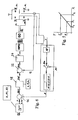
- control unit 44 comprises a position control loop 45 which receives the position signal X from position sensor 38 and compares it with a reference variable X_ref in a first subtracter block 46, thereby obtaining a position error Xerr.
- a position compensator 48 processes the value Xerr and outputs a corresponding reference current Iref.
- An inner, current control loop 50 receives current signal Iref in a second subtracter block 52 and compares it with the current I across the actuator, thereby obtaining a current error Ierr. In a known way, current error Ierr is sent to a current compensator 54 that processes this signal to obtain a voltage value V.
- the latter supplies a wave form generator WFG which generates four low-level pilot signals GL1-GL4 which drive respective MOS field effect transistors Q1-Q4, usually called MOSFET (Metal Oxide Semiconductor Field Effect Transistor), which are arranged to form an H-bridge 58 which pilots a respective one of said actuators 26, 28.
- MOSFET Metal Oxide Semiconductor Field Effect Transistor
- a gate driver GD is arranged between wave form generator WFG and bridge 58, in order to shift signals GL1-GL4 to voltage levels G1-G4 compatible with the gate of MOSFETs Q1-Q4 of bridge 58.
- the braking assembly according to this invention is representable by means of an equivalent mass-spring system, with an equivalent mass corresponding to the mass of the parts in motion, i.e., rods 26a, 28a, magnets 40, annular support 30 and springs 34, and an elastic constant k which takes into account both the stiffness of the springs forming the spider assembly, and the elastic yelding of the frustoconical member.
- Position compensator 48 also includes a transfer function which changes as a function of elastic constant k, and is connected for receiving variable values of said elastic constant k which are calculated by executing a preliminary tuning procedure in control unit 44.
- the driving force Fm exerted by the actuator is calculated by multiplying the current i across the actuator by a force constant Kf, which usually is assigned to the actuator, but can also be calculated, as will be better described below.
- the preload force F1 of the springs which is measured with the rod in its innermost stop position (resting position), is subtracted from the driving force Fm, thereby obtaining resulting force Fr that is applied to a transfer function of the type: 1 s 2 ⁇ m + s ⁇ h + k , where m is the mass of the parts in motion, h is the viscous friction coefficient of the system, k is the elastic constant, and s is the complex pulsation, in order to obtain a corresponding displacement X.
- the tuning method comprises the steps of:
- the above method allows both the equivalent elastic constant k and the force constant kf of the actuators to be determined.
- the tuning method comprises the steps of:
- the equivalent elastic constant is the angular coefficient of the line of Fig. 5, which line represents the force F as a function of the displacement X in the equivalent system (X0 is the position with the springs at rest).
- the above-described tuning methods are particularly suited to be automatized by means of computer-assisted processing techniques, which are intended to be known to the person skilled in the art, e.g., by incorporating their procedures in the feeder-starting routine so that, when the feeder is started, the control unit is automatically set to the parameters of stiffness and preload of the system.
- the measured values of elastic constant k, force constant kf, and preload F1 may also be visualized, e.g., on a monitor accessible to the operator, in a conventional way, in order to supply the operator with informations useful for manually tuning the system.
Landscapes
- Engineering & Computer Science (AREA)
- Textile Engineering (AREA)
- Looms (AREA)
- Tension Adjustment In Filamentary Materials (AREA)
- Control Of Position Or Direction (AREA)
Applications Claiming Priority (1)
| Application Number | Priority Date | Filing Date | Title |
|---|---|---|---|
| IT000484A ITTO20050484A1 (it) | 2005-07-14 | 2005-07-14 | Unita' di controllo per dispositivi di frenatura del filato in alimentatori di trama per telai di tessitura, e procedura di sintonizzazione della stessa |
Publications (3)
| Publication Number | Publication Date |
|---|---|
| EP1743967A2 true EP1743967A2 (fr) | 2007-01-17 |
| EP1743967A3 EP1743967A3 (fr) | 2009-01-21 |
| EP1743967B1 EP1743967B1 (fr) | 2010-01-20 |
Family
ID=37075962
Family Applications (1)
| Application Number | Title | Priority Date | Filing Date |
|---|---|---|---|
| EP06009711A Expired - Lifetime EP1743967B1 (fr) | 2005-07-14 | 2006-05-11 | Unité de contrôle pour dispositif de freinage de fil dans des fournisseurs de trame pour métiers à tisser et procédé de réglage associé |
Country Status (5)
| Country | Link |
|---|---|
| US (1) | US7584014B2 (fr) |
| EP (1) | EP1743967B1 (fr) |
| CN (1) | CN1896356B (fr) |
| DE (1) | DE602006011826D1 (fr) |
| IT (1) | ITTO20050484A1 (fr) |
Cited By (2)
| Publication number | Priority date | Publication date | Assignee | Title |
|---|---|---|---|---|
| WO2019032007A1 (fr) | 2017-08-08 | 2019-02-14 | Iro Aktiebolag | Frein de fil réglable |
| EP3414378A4 (fr) * | 2016-02-09 | 2019-02-27 | IRO Aktiebolag | Prédélivreur avec frein de fil réglable électriquement |
Families Citing this family (10)
| Publication number | Priority date | Publication date | Assignee | Title |
|---|---|---|---|---|
| US7543610B2 (en) * | 2006-06-16 | 2009-06-09 | Sultex Ag | Thread clamp for a rapier head |
| EP1961686B1 (fr) * | 2007-02-20 | 2016-09-14 | Iro Ab | Système de surveillance et de règlage de tension de fil |
| WO2009025803A1 (fr) | 2007-08-20 | 2009-02-26 | Kevin Kremeyer | Systèmes de dépôt d'énergie, équipement et procédés permettant de modifier et de commander des ondes de choc et un écoulement supersonique |
| EP2031106B1 (fr) * | 2007-08-31 | 2010-02-24 | L.G.L. Electronics S.p.A. | Procédé de controle de tension d'un fil délivré par un fournisseur négatif vers une machine textile, et dispositif permettant de mettre en oeuvre le procédé |
| US8150543B2 (en) * | 2007-09-28 | 2012-04-03 | Siemens Aktiengesellschaft | Methods, apparatus and articles for an air jet loom |
| EP2169099A1 (fr) * | 2008-09-25 | 2010-03-31 | L.G.L. Electronics S.p.A. | Dispositif d'alimentation négative de fils avec un dispositif de freinage de trame |
| EP2415916B1 (fr) * | 2010-08-04 | 2015-03-04 | L.G.L. Electronics S.p.A. | Procédé et appareil pour détecter des arrêts accidentels de fil dans une chaîne de fabrication tricotage |
| CN102505288B (zh) * | 2011-10-19 | 2013-09-25 | 宁波宏大纺织仪器有限公司 | 一种止纱销控制方法及利用该方法的装置 |
| US10669653B2 (en) * | 2015-06-18 | 2020-06-02 | Kevin Kremeyer | Directed energy deposition to facilitate high speed applications |
| CN117188017B (zh) * | 2023-09-18 | 2025-11-04 | 天津工业大学 | 一种控制剑杆引纬纬纱交接的方法 |
Family Cites Families (15)
| Publication number | Priority date | Publication date | Assignee | Title |
|---|---|---|---|---|
| DE4108238A1 (de) * | 1990-06-29 | 1992-01-02 | Sobrevin | Fadenliefervorrichtung |
| BE1009297A3 (fr) * | 1993-04-16 | 1997-02-04 | Nissan Texsys Co Ltd | Systeme d'insertion de trame pour metier a jet de fluide. |
| IT1268111B1 (it) * | 1994-10-10 | 1997-02-20 | Lgl Electronics Spa | Dispositivo di frenatura modulata positiva del filato, per apparecchi alimentatori di trama |
| IT1282898B1 (it) * | 1995-09-20 | 1998-04-01 | Mario Gallo | Dispositivo per controllare la tensione di un filo. |
| DE19756243A1 (de) * | 1997-12-17 | 1999-06-24 | Iro Ab | Fadenliefergerät |
| IT1308067B1 (it) * | 1999-06-01 | 2001-11-29 | Lgl Electronics Spa | Dispositivo di frenatura del filato, per alimentatore di trama,avente tempi di intervento ridotti |
| IT1311256B1 (it) * | 1999-10-26 | 2002-03-04 | Lgl Electronics Spa | Dispositivo e metodo di movimentazione e controllo del braccioavvolgitrama negli apparecchi alimentatori di trama per telai di |
| IT1310749B1 (it) * | 1999-11-30 | 2002-02-22 | Lgl Electronics Spa | Metodo e dispositivo di controllo di freni di trama elettrocomandatiper la regolazione automatica della tensione meccanica del filo di |
| DE10013625A1 (de) * | 2000-03-18 | 2001-09-27 | Dornier Gmbh Lindauer | Fadenbremse, insbesondere Schussfadenbremse für Webmaschinen |
| NL1014729C2 (nl) * | 2000-03-23 | 2001-09-25 | Te Strake Bv | Werkwijze voor het opnemen en tellen van van een trommel aflopende wikkelingen, alsmede een inrichting voor het uitvoeren van deze werkwijze. |
| DE10017466A1 (de) * | 2000-04-07 | 2001-10-11 | Iro Patent Ag Baar | Verfahren zum Steuern eines Schussfaden-Liefergeräts in einem fadenverarbeitenden System und fadenverarbeitenden System |
| ITTO20010260A1 (it) * | 2001-03-20 | 2002-09-20 | Lgl Electronics Spa | Dispositivo di frenatura autoregolante per apparecchi alimentatori ditrama. |
| ITTO20010737A1 (it) * | 2001-07-25 | 2003-01-25 | Lgl Electronics Spa | Metodo e sistema perfezionati di controllo dei dispositivi frenatramaelettrocomandati per la regolazione automatica della tensione meccanic |
| ITTO20020857A1 (it) * | 2002-10-04 | 2004-04-05 | L G L Electronics Spa | Dispositivo di controllo del freno di trama per telai di tessitura |
| US7039489B2 (en) * | 2004-03-12 | 2006-05-02 | Sultex Ag | Monitoring of thread transport |
-
2005
- 2005-07-14 IT IT000484A patent/ITTO20050484A1/it unknown
-
2006
- 2006-05-11 EP EP06009711A patent/EP1743967B1/fr not_active Expired - Lifetime
- 2006-05-11 DE DE602006011826T patent/DE602006011826D1/de not_active Expired - Lifetime
- 2006-06-20 US US11/455,830 patent/US7584014B2/en not_active Expired - Fee Related
- 2006-07-13 CN CN2006101057125A patent/CN1896356B/zh not_active Expired - Fee Related
Cited By (2)
| Publication number | Priority date | Publication date | Assignee | Title |
|---|---|---|---|---|
| EP3414378A4 (fr) * | 2016-02-09 | 2019-02-27 | IRO Aktiebolag | Prédélivreur avec frein de fil réglable électriquement |
| WO2019032007A1 (fr) | 2017-08-08 | 2019-02-14 | Iro Aktiebolag | Frein de fil réglable |
Also Published As
| Publication number | Publication date |
|---|---|
| CN1896356A (zh) | 2007-01-17 |
| DE602006011826D1 (de) | 2010-03-11 |
| ITTO20050484A1 (it) | 2007-01-15 |
| EP1743967B1 (fr) | 2010-01-20 |
| CN1896356B (zh) | 2011-03-30 |
| US20070028989A1 (en) | 2007-02-08 |
| US7584014B2 (en) | 2009-09-01 |
| EP1743967A3 (fr) | 2009-01-21 |
Similar Documents
| Publication | Publication Date | Title |
|---|---|---|
| EP1743967B1 (fr) | Unité de contrôle pour dispositif de freinage de fil dans des fournisseurs de trame pour métiers à tisser et procédé de réglage associé | |
| KR100293028B1 (ko) | 실의장력제어장치및방법과실공급기 | |
| JP2541574B2 (ja) | 電子的糸張力制御機能を有する給糸装置 | |
| KR100302035B1 (ko) | 탄성사를위한사공급장치및사용방법과,그를이용한편물제품 | |
| EP0290039B1 (fr) | Procédé et dispositif pour contrôler la tension des fils de chaîne poil | |
| JP2011514939A (ja) | 非連続状態で供給される糸又は糸状体を一定張力で供給する装置及び方法 | |
| US4687151A (en) | Textile yarn pull-off system | |
| TWI568901B (zh) | 控制導線之方法、導線器及具有導線器之系統 | |
| EP2924156A1 (fr) | Dispositif de freinage de fil pour dispositifs d'alimentation en fil de stockage | |
| EP1524342A2 (fr) | Ourdisseur pour les fils de chaíne | |
| US6810918B2 (en) | Method and apparatus for variably braking the weft thread between a supply spool and a thread store in a loom | |
| CN100439582C (zh) | 自动调节在纺织机中纱线机械张力的纬纱制动设备的控制方法 | |
| EP2041546B1 (fr) | Microscope à sonde à balayage et son procédé de fonctionnement | |
| JPS6233852A (ja) | 織機のワ−プビ−ム駆動装置を制御する方法並びに装置 | |
| EP0590725B1 (fr) | Dispositif de contrôle automatique de la tension de la chaíne dans un métier à tisser | |
| EP0667203B1 (fr) | Systeme de regulation de la tension d'un fil | |
| US6054835A (en) | Stepping motor control, and operating mode of such motors | |
| SU792320A1 (ru) | Устройство дл выравнивани колебаний нат жени длинномерного издели при намотке | |
| US5538048A (en) | System and method for regulating the cloth fell position in a loom | |
| EP0796937A2 (fr) | Dispositif de commande pour métier à tisser sans navette | |
| GB2392740A (en) | A system and apparatus for film tension control. | |
| KR100747154B1 (ko) | 케이블 장력 자동 보정장치 | |
| Schröder et al. | Adaptive state space control for axial winders | |
| JPH039222B2 (fr) | ||
| JPH024134Y2 (fr) |
Legal Events
| Date | Code | Title | Description |
|---|---|---|---|
| PUAI | Public reference made under article 153(3) epc to a published international application that has entered the european phase |
Free format text: ORIGINAL CODE: 0009012 |
|
| AK | Designated contracting states |
Kind code of ref document: A2 Designated state(s): AT BE BG CH CY CZ DE DK EE ES FI FR GB GR HU IE IS IT LI LT LU LV MC NL PL PT RO SE SI SK TR |
|
| AX | Request for extension of the european patent |
Extension state: AL BA HR MK YU |
|
| PUAL | Search report despatched |
Free format text: ORIGINAL CODE: 0009013 |
|
| AK | Designated contracting states |
Kind code of ref document: A3 Designated state(s): AT BE BG CH CY CZ DE DK EE ES FI FR GB GR HU IE IS IT LI LT LU LV MC NL PL PT RO SE SI SK TR |
|
| AX | Request for extension of the european patent |
Extension state: AL BA HR MK YU |
|
| 17P | Request for examination filed |
Effective date: 20090206 |
|
| AKX | Designation fees paid |
Designated state(s): BE CH DE LI SE |
|
| GRAP | Despatch of communication of intention to grant a patent |
Free format text: ORIGINAL CODE: EPIDOSNIGR1 |
|
| GRAS | Grant fee paid |
Free format text: ORIGINAL CODE: EPIDOSNIGR3 |
|
| GRAA | (expected) grant |
Free format text: ORIGINAL CODE: 0009210 |
|
| AK | Designated contracting states |
Kind code of ref document: B1 Designated state(s): BE CH DE LI SE |
|
| REG | Reference to a national code |
Ref country code: CH Ref legal event code: EP |
|
| REF | Corresponds to: |
Ref document number: 602006011826 Country of ref document: DE Date of ref document: 20100311 Kind code of ref document: P |
|
| REG | Reference to a national code |
Ref country code: SE Ref legal event code: TRGR |
|
| PLBE | No opposition filed within time limit |
Free format text: ORIGINAL CODE: 0009261 |
|
| STAA | Information on the status of an ep patent application or granted ep patent |
Free format text: STATUS: NO OPPOSITION FILED WITHIN TIME LIMIT |
|
| 26N | No opposition filed |
Effective date: 20101021 |
|
| REG | Reference to a national code |
Ref country code: CH Ref legal event code: PL |
|
| PG25 | Lapsed in a contracting state [announced via postgrant information from national office to epo] |
Ref country code: LI Free format text: LAPSE BECAUSE OF NON-PAYMENT OF DUE FEES Effective date: 20100531 Ref country code: CH Free format text: LAPSE BECAUSE OF NON-PAYMENT OF DUE FEES Effective date: 20100531 |
|
| PGFP | Annual fee paid to national office [announced via postgrant information from national office to epo] |
Ref country code: SE Payment date: 20180518 Year of fee payment: 13 |
|
| PG25 | Lapsed in a contracting state [announced via postgrant information from national office to epo] |
Ref country code: SE Free format text: LAPSE BECAUSE OF NON-PAYMENT OF DUE FEES Effective date: 20190512 |
|
| REG | Reference to a national code |
Ref country code: SE Ref legal event code: EUG |
|
| PGFP | Annual fee paid to national office [announced via postgrant information from national office to epo] |
Ref country code: DE Payment date: 20230505 Year of fee payment: 18 |
|
| PGFP | Annual fee paid to national office [announced via postgrant information from national office to epo] |
Ref country code: BE Payment date: 20240516 Year of fee payment: 19 |
|
| REG | Reference to a national code |
Ref country code: DE Ref legal event code: R119 Ref document number: 602006011826 Country of ref document: DE |
|
| PG25 | Lapsed in a contracting state [announced via postgrant information from national office to epo] |
Ref country code: DE Free format text: LAPSE BECAUSE OF NON-PAYMENT OF DUE FEES Effective date: 20241203 |
|
| REG | Reference to a national code |
Ref country code: BE Ref legal event code: MM Effective date: 20250531 |
|
| PG25 | Lapsed in a contracting state [announced via postgrant information from national office to epo] |
Ref country code: BE Free format text: LAPSE BECAUSE OF NON-PAYMENT OF DUE FEES Effective date: 20250531 |