EP1744072B1 - Procede de fabrication d'un ensemble palier et palier - Google Patents
Procede de fabrication d'un ensemble palier et palier Download PDFInfo
- Publication number
- EP1744072B1 EP1744072B1 EP06013776A EP06013776A EP1744072B1 EP 1744072 B1 EP1744072 B1 EP 1744072B1 EP 06013776 A EP06013776 A EP 06013776A EP 06013776 A EP06013776 A EP 06013776A EP 1744072 B1 EP1744072 B1 EP 1744072B1
- Authority
- EP
- European Patent Office
- Prior art keywords
- bearing
- carrier
- assembly according
- plastics
- bearing assembly
- Prior art date
- Legal status (The legal status is an assumption and is not a legal conclusion. Google has not performed a legal analysis and makes no representation as to the accuracy of the status listed.)
- Not-in-force
Links
Images


Classifications
-
- B—PERFORMING OPERATIONS; TRANSPORTING
- B29—WORKING OF PLASTICS; WORKING OF SUBSTANCES IN A PLASTIC STATE IN GENERAL
- B29C—SHAPING OR JOINING OF PLASTICS; SHAPING OF MATERIAL IN A PLASTIC STATE, NOT OTHERWISE PROVIDED FOR; AFTER-TREATMENT OF THE SHAPED PRODUCTS, e.g. REPAIRING
- B29C45/00—Injection moulding, i.e. forcing the required volume of moulding material through a nozzle into a closed mould; Apparatus therefor
- B29C45/14—Injection moulding, i.e. forcing the required volume of moulding material through a nozzle into a closed mould; Apparatus therefor incorporating preformed parts or layers, e.g. injection moulding around inserts or for coating articles
- B29C45/1459—Coating annular articles
-
- F—MECHANICAL ENGINEERING; LIGHTING; HEATING; WEAPONS; BLASTING
- F16—ENGINEERING ELEMENTS AND UNITS; GENERAL MEASURES FOR PRODUCING AND MAINTAINING EFFECTIVE FUNCTIONING OF MACHINES OR INSTALLATIONS; THERMAL INSULATION IN GENERAL
- F16C—SHAFTS; FLEXIBLE SHAFTS; ELEMENTS OR CRANKSHAFT MECHANISMS; ROTARY BODIES OTHER THAN GEARING ELEMENTS; BEARINGS
- F16C19/00—Bearings with rolling contact, for exclusively rotary movement
- F16C19/54—Systems consisting of a plurality of bearings with rolling friction
-
- F—MECHANICAL ENGINEERING; LIGHTING; HEATING; WEAPONS; BLASTING
- F16—ENGINEERING ELEMENTS AND UNITS; GENERAL MEASURES FOR PRODUCING AND MAINTAINING EFFECTIVE FUNCTIONING OF MACHINES OR INSTALLATIONS; THERMAL INSULATION IN GENERAL
- F16C—SHAFTS; FLEXIBLE SHAFTS; ELEMENTS OR CRANKSHAFT MECHANISMS; ROTARY BODIES OTHER THAN GEARING ELEMENTS; BEARINGS
- F16C35/00—Rigid support of bearing units; Housings, e.g. caps, covers
- F16C35/04—Rigid support of bearing units; Housings, e.g. caps, covers in the case of ball or roller bearings
- F16C35/042—Housings for rolling element bearings for rotary movement
- F16C35/045—Housings for rolling element bearings for rotary movement with a radial flange to mount the housing
-
- F—MECHANICAL ENGINEERING; LIGHTING; HEATING; WEAPONS; BLASTING
- F16—ENGINEERING ELEMENTS AND UNITS; GENERAL MEASURES FOR PRODUCING AND MAINTAINING EFFECTIVE FUNCTIONING OF MACHINES OR INSTALLATIONS; THERMAL INSULATION IN GENERAL
- F16C—SHAFTS; FLEXIBLE SHAFTS; ELEMENTS OR CRANKSHAFT MECHANISMS; ROTARY BODIES OTHER THAN GEARING ELEMENTS; BEARINGS
- F16C35/00—Rigid support of bearing units; Housings, e.g. caps, covers
- F16C35/04—Rigid support of bearing units; Housings, e.g. caps, covers in the case of ball or roller bearings
- F16C35/06—Mounting or dismounting of ball or roller bearings; Fixing them onto shaft or in housing
- F16C35/067—Fixing them in a housing
-
- B—PERFORMING OPERATIONS; TRANSPORTING
- B29—WORKING OF PLASTICS; WORKING OF SUBSTANCES IN A PLASTIC STATE IN GENERAL
- B29C—SHAPING OR JOINING OF PLASTICS; SHAPING OF MATERIAL IN A PLASTIC STATE, NOT OTHERWISE PROVIDED FOR; AFTER-TREATMENT OF THE SHAPED PRODUCTS, e.g. REPAIRING
- B29C45/00—Injection moulding, i.e. forcing the required volume of moulding material through a nozzle into a closed mould; Apparatus therefor
- B29C45/0053—Injection moulding, i.e. forcing the required volume of moulding material through a nozzle into a closed mould; Apparatus therefor combined with a final operation, e.g. shaping
-
- B—PERFORMING OPERATIONS; TRANSPORTING
- B29—WORKING OF PLASTICS; WORKING OF SUBSTANCES IN A PLASTIC STATE IN GENERAL
- B29L—INDEXING SCHEME ASSOCIATED WITH SUBCLASS B29C, RELATING TO PARTICULAR ARTICLES
- B29L2031/00—Other particular articles
- B29L2031/04—Bearings
-
- F—MECHANICAL ENGINEERING; LIGHTING; HEATING; WEAPONS; BLASTING
- F16—ENGINEERING ELEMENTS AND UNITS; GENERAL MEASURES FOR PRODUCING AND MAINTAINING EFFECTIVE FUNCTIONING OF MACHINES OR INSTALLATIONS; THERMAL INSULATION IN GENERAL
- F16C—SHAFTS; FLEXIBLE SHAFTS; ELEMENTS OR CRANKSHAFT MECHANISMS; ROTARY BODIES OTHER THAN GEARING ELEMENTS; BEARINGS
- F16C2220/00—Shaping
- F16C2220/02—Shaping by casting
- F16C2220/04—Shaping by casting by injection-moulding
-
- F—MECHANICAL ENGINEERING; LIGHTING; HEATING; WEAPONS; BLASTING
- F16—ENGINEERING ELEMENTS AND UNITS; GENERAL MEASURES FOR PRODUCING AND MAINTAINING EFFECTIVE FUNCTIONING OF MACHINES OR INSTALLATIONS; THERMAL INSULATION IN GENERAL
- F16C—SHAFTS; FLEXIBLE SHAFTS; ELEMENTS OR CRANKSHAFT MECHANISMS; ROTARY BODIES OTHER THAN GEARING ELEMENTS; BEARINGS
- F16C2226/00—Joining parts; Fastening; Assembling or mounting parts
- F16C2226/30—Material joints
-
- F—MECHANICAL ENGINEERING; LIGHTING; HEATING; WEAPONS; BLASTING
- F16—ENGINEERING ELEMENTS AND UNITS; GENERAL MEASURES FOR PRODUCING AND MAINTAINING EFFECTIVE FUNCTIONING OF MACHINES OR INSTALLATIONS; THERMAL INSULATION IN GENERAL
- F16C—SHAFTS; FLEXIBLE SHAFTS; ELEMENTS OR CRANKSHAFT MECHANISMS; ROTARY BODIES OTHER THAN GEARING ELEMENTS; BEARINGS
- F16C2361/00—Apparatus or articles in engineering in general
- F16C2361/61—Toothed gear systems, e.g. support of pinion shafts
-
- F—MECHANICAL ENGINEERING; LIGHTING; HEATING; WEAPONS; BLASTING
- F16—ENGINEERING ELEMENTS AND UNITS; GENERAL MEASURES FOR PRODUCING AND MAINTAINING EFFECTIVE FUNCTIONING OF MACHINES OR INSTALLATIONS; THERMAL INSULATION IN GENERAL
- F16C—SHAFTS; FLEXIBLE SHAFTS; ELEMENTS OR CRANKSHAFT MECHANISMS; ROTARY BODIES OTHER THAN GEARING ELEMENTS; BEARINGS
- F16C2361/00—Apparatus or articles in engineering in general
- F16C2361/65—Gear shifting, change speed gear, gear box
Definitions
- the invention relates to a method for producing a bearing arrangement, which has a bearing carrier which has at least one first bearing for at least radial mounting of a shaft part and at least one second bearing for the radial mounting of a rod-shaped component. Furthermore, the invention relates to a bearing assembly.
- Bearing arrangements of this type are known in the art. They are used in particular in transmissions in which on the one hand gear shafts must be stored and on the other hand must have a storage option for gear shift rods.
- the DE 199 61 224 A1 shows a trained as a sheet metal bearing carrier, which receives two juxtaposed bearings.
- the bearing carrier is formed without cutting.
- the carrier is provided for a manual transmission, which also includes shift shafts. To store this, the bearing carrier has sleeve-shaped sections which are molded into it.
- a plate-shaped bearing carrier made of sheet metal which has two molded seat surfaces for receiving a respective bearing.
- the bearing carrier further comprises two formed outside the seats sleeves, which are provided for guiding or storing shift rails.
- a bearing carrier for receiving a bearing assembly for a shaft is known, in which case the bearing carrier consists of plastic. It is manufactured as an injection molded part connected to the bearing assembly by overmoulding.
- the invention is therefore based on the object to provide a method for producing a bearing assembly and such a bearing assembly, with which or with which it is possible to avoid the above drawbacks. It should therefore be achieved that the production of the bearing carrier can be done in a simpler and thus more cost-effective manner than has hitherto been the case, yet should be worn for precise storage of the waves to be stored and also of rods, in particular shift linkage, care.
- the bearing carrier should still have a very high mechanical strength.
- the mounting of the bearing carrier should be much easier than that for previously known solutions.
- the bearing carrier should be characterized by a low weight.
- the invention thus provides that in a first process step, first a plastic carrier part is prefabricated, in which the in-situ at least one bearing ring of the second bearing is connected to the carrier part, which can be done in a classical manner by encapsulation of the bearing ring.
- the second bearing is preferably the shift linkage bearing or the shift linkage guide in a manual transmission.
- the bearing carrier is produced from sheet metal, which is equipped to accommodate the at least one bearing for supporting the shaft part, in particular a gear shaft, for which purpose the receptacle for the bearing ring of the first bearing is formed.
- the bearing carrier may also consist of any intrinsically rigid material, for example of metallic material, such as sheet metal, light metal (in particular light metal casting, ie preferably aluminum or magnesium casting) or cast steel.
- the Receiving the plastic support member may be formed as a recess or as any desired holder.
- a first development provides that during injection molding of the plastic carrier part according to the above step a) the at least one bearing ring of the second bearing is axially encapsulated on at least one side in order to create an axial wrap around the bearing ring; Preferably, a double-sided axial encapsulation is provided.
- the plastic carrier part is provided with at least one connecting portion.
- This can be formed as a planar extension over the base part of the support member, so as to be able to later fix the support part to the bearing support.
- a flat sheet metal part is preferably formed by forming, in particular by stamping, pressing and / or deep drawing, to the bearing carrier.
- the fixing of the plastic carrier part in the receptacle or recess of the bearing carrier according to the above step c) can be done by screwing or by riveting or otherwise, with a firm connection between the plastic support member and bearing support can be achieved.
- the bearing arrangement which has a bearing carrier which has at least one first bearing for at least radial mounting of a shaft part and at least one second bearing for the radial mounting of a rod-shaped component, is designed according to the invention such that the bearing carrier consists of a part of inherently rigid material, in particular of a sheet metal part, and provided for receiving a plastic support member receptacle or recess and at least one receptacle for a bearing ring of the first bearing, wherein in the receptacle, the plastic support member is inserted Has at least one bearing ring of the second bearing, which is connected during injection molding of the plastic support member in situ with the plastic support member, and wherein the plastic support member is fixed to the bearing support.
- the plastic support member preferably surrounds the at least one bearing ring of the second bearing at least on one side, preferably on both sides, axially by means of at least one axial wrap.
- the first bearing is preferably a rolling bearing. It is also possible to provide two first bearings side by side in the bearing carrier, their axes of rotation being aligned parallel to one another.
- the second bearing may be a rolling bearing. It can be arranged between the bearing ring of the second bearing and the rod-shaped component a rolling element set or set of rollers. In this case, therefore, a bearing inner ring is dispensed with; this is formed by the rod-shaped component itself.
- the rolling element set or set of rollers may have a cage. But it is also possible that the second bearing is a plain bearing.
- the bearing carrier in the region of the receptacle for the bearing ring of the first bearing engages in an annular groove in the outer circumference of the bearing ring of the first bearing.
- the bearing carrier in the region of the receptacle for the bearing ring of the first bearing is cup-shaped and forms a seat portion for the outer periphery of the bearing ring of the first bearing.
- the bearing carrier In order to fix the bearing assembly, the bearing carrier, preferably at its outer radial portion, have a number of fasteners.
- the fasteners may be holes for the passage of a screw. They can also be threaded holes for co-operating with a screw.
- it In order to increase the strength of the connection of the bearing carrier, it may have an increased thickness in the region of the fastening elements, it may also have a broadening in the radial direction in the region of the fastening elements.
- the bearing carrier is advantageously made of hardened steel.
- the shaft part which is supported by means of the bearing assembly, part of a transmission shaft, in particular a motor vehicle transmission.
- the rod-shaped component is preferably the shift rod of a transmission, in particular a motor vehicle transmission.
- the assembly of a transmission can be done in a completely new way, since it is not necessary to mount the transmission shafts and the shift linkage simultaneously.
- the shift linkage can for example - be added to the bearing bracket - pre-assembled with the plastic support member - when the transmission shafts are already fully assembled by means of the bearing carrier.
- the bearing carrier thus produced is characterized by a low weight, as seen from the force application ago Subordinate storage of the shift linkage, a plastic part can be used.
- the proposed bearing arrangement is preferably used in passenger car transmissions. Basically, however, it is suitable for all applications in which the bearing is connected to a bearing carrier used as a unit.
- Fig. 1 an injection molding is shown, which consists essentially of a plastic support member 7. This has been manufactured in the classic injection molding process, using a known plastic material is used. This can be both a thermoplastic and a duroplastic, the choice of material depending on the later application of the bearing assembly.
- the two second bearings 5 serve to support or guide two shift rails of a passenger car manual transmission.
- the shift rails are as rod-shaped components in Fig. 3 marked with the reference number 6.
- the support member 7 on connecting portions 13 which are formed as a surface continuations of the support member body and have holes by which they later on in Fig. 2 sketched bearing carrier 2 can be set.
- the support member 7 has in plan view a substantially quadrangular, block-shaped configuration, as in Fig. 3 can be seen.
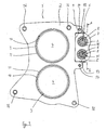
- the bearing carrier 2 produced without cutting from a flat sheet metal part is in Fig. 2 to see.
- An important part of the bearing support 2 are once the circular receptacles 10 for the bearing outer rings 11 of two first bearing 3, which are provided for supporting two parallel juxtaposed shaft part 4 in the form of transmission shafts.
- Another important component of the bearing carrier 2 is a recess 9 in the bearing carrier, which is designed to receive the plastic carrier part 7.
- the recess 9 therefore has a shape corresponding to the shape of the carrier part 7.
- fastening elements 16 are provided with which the bearing carrier 2 can be screwed to the transmission housing, for example.
- the plastic support member 7 is fixed after accurately fitting insertion into the recess 9 in the bearing bracket 2 by means of the connecting portions 13 and only schematically indicated screw 14 on the bearing bracket 2. It is possible that even before setting the plastic support member 7 on the bearing bracket 2, the shift rails 6 are pre-assembled in the support member 7, that this is therefore a preassembled unit, which is very advantageous montagetechnisch. It can be a separate press-fitting of the outer ring 8 of the second bearing 5 - as in the prior art - omitted.
- the rods 6 are supported by that it is with a rolling element 15 - the proposed cage is in Fig. 3 not shown - be provided, which runs in the bearing rings 8. In this case, the rods 6 thus act themselves as inner rings of the second bearing. 5
- Rolling bearings for the rod-shaped components 6 are provided in the exemplary embodiment. However, sliding bearings may also be used here, in which case the bearing rings 8 are sliding sleeves.
- plastic carrier part 7 takes place in the embodiment by means of screwing. However, it can be provided here any shape, force or cohesive connection.
Landscapes
- Engineering & Computer Science (AREA)
- General Engineering & Computer Science (AREA)
- Mechanical Engineering (AREA)
- Manufacturing & Machinery (AREA)
- Mounting Of Bearings Or Others (AREA)
- Injection Moulding Of Plastics Or The Like (AREA)
- Sliding-Contact Bearings (AREA)
Claims (29)
- Procédé de fabrication d'un ensemble de paliers (1) comprenant un support de paliers (2) qui présente au moins un premier palier (3) pour le support, au moins radial, d'un élément d'arbre (4) et au moins un deuxième palier (5) pour le support radial d'un élément (6) en forme de barre,
caractérisé par le fait qu'il comprend les étapes suivantes :a) fabrication d'un élément support (7) en matière plastique par moulage par injection, lors de laquelle une bague de palier (8) du deuxième palier (5) est reliée de façon permanente à l'élément support (7) en matière plastique, par l'opération de moulage par injection,b) fabrication d'un support de paliers (2) en matériau à rigidité intrinsèque, lors de laquelle un logement (9), destiné à recevoir l'élément support (7) en matière plastique, est réalisé dans le support de paliers (2) et au moins un logement (10), destiné à recevoir une bague de palier (11) du premier palier (3) est réalisé,c) mise en place et fixation de l'élément support (7) en matière plastique dans le logement (9) prévu à cet effet du support de paliers (2). - Procédé selon la revendication 1, caractérisé par le fait que lors du moulage par injection de l'élément support (7) en matière plastique selon l'étape a) de la revendication 1, la bague de palier (8), au nombre d'au moins une, du deuxième palier (5) est surmoulée par injection dans le sens axial, au moins sur un côté, afin de créer un rebord (12) axial entourant la bague de palier (8).
- Procédé selon la revendication 2, caractérisé par le fait que lors du moulage par injection de l'élément support (7) en matière plastique, la bague de palier (8), au nombre d'au moins une, du deuxième palier (5) est surmoulée par injection axialement sur les deux côtés.
- Procédé selon une des revendications 1 à 3, caractérisé par le fait que lors du moulage par injection de l'élément support (7) en matière plastique selon l'étape a) de la revendication 1, ledit élément support (7) en matière plastique est pourvu d'au moins une partie d'assemblage (13).
- Procédé selon une des revendications 1 à 4, caractérisé par le fait que lors de la fabrication du support de paliers (2) selon l'étape b) de la revendication 1, une pièce de tôle plane est soumise à un formage, notamment par découpage, compression et/ou emboutissage, pour réaliser le support de paliers (2).
- Procédé selon une des revendications 1 à 5, caractérisé par le fait que la fixation de l'élément support (7) en matière plastique dans le logement (9) du support de paliers (2) selon l'étape c) de la revendication 1 est réalisée par vissage.
- Procédé selon une des revendications 1 à 5, caractérisé par le fait que la fixation de l'élément support (7) en matière plastique dans le logement (9) du support de palier (2) selon l'étape c) de la revendication 1 est réalisée par rivetage.
- Ensemble de paliers (1) comprenant un support de paliers (2) qui présente au moins un premier palier (3) pour le support, au moins radial, d'un élément d'arbre (4) et au moins un deuxième palier (5) pour le support radial d'un élément (6) en forme de barre,
caractérisé par le fait que
le support de paliers (2) est constitué d'un élément en matériau à rigidité intrinsèque et présente un logement (9), destiné à recevoir un élément support (7) en matière plastique, et au moins un logement (10) pour une bague de palier (11) du premier palier (3), sachant que le logement (9) reçoit l'élément support (7) en matière plastique qui présente au moins une bague de palier (8) du deuxième palier (5), lequel est relié in situ à l'élément support (7) en matière plastique, lors du moulage par injection de l'élément support (7) en matière plastique, et ledit élément support (7) en matière plastique est fixé au support de paliers (2). - Ensemble de paliers selon la revendication 8, caractérisé par le fait que l'élément support (7) en matière plastique entoure la bague de palier (8), au nombre d'au moins une, du deuxième palier (5) axialement sur au moins un côté, au moyen d'un rebord (12) axial.
- Ensemble de paliers selon la revendication 9, caractérisé par le fait que l'élément support (7) en matière plastique entoure la bague de palier (8), au nombre d'au moins une, du deuxième palier (5) axialement sur les deux côtés, au moyen de rebords (12) axiaux.
- Ensemble de paliers selon une des revendications 8 à 10, caractérisé par le fait que l'élément support (7) en matière plastique présente au moins une partie d'assemblage (13), par laquelle ledit élément support (7) en matière plastique est fixé au support de paliers (2).
- Ensemble de paliers selon une des revendications 8 à 11, caractérisé par le fait que le support de paliers (2) est constitué d'une pièce de tôle plane qui est soumise à un formage, notamment par découpage, compression et/ou emboutissage, pour réaliser le support de paliers (2).
- Ensemble de paliers selon une des revendications 8 à 12, caractérisé par le fait que l'élément support (7) en matière plastique est fixé par un assemblage vissé (14) dans le logement (9) du support de paliers (2).
- Ensemble de paliers selon une des revendications 8 à 12, caractérisé par le fait que l'élément support (7) en matière plastique est fixé par un assemblage riveté dans le logement (9) du support de paliers (2).
- Ensemble de paliers selon une des revendications 8 à 14, caractérisé par le fait que le premier palier (3) est un palier à roulement.
- Ensemble de paliers selon une des revendications 8 à 15, caractérisé par le fait que deux premiers paliers (3) sont disposés l'un à côté de l'autre dans le support de paliers (2), leurs axes de rotation étant orientés parallèlement l'un à l'autre.
- Ensemble de paliers selon une des revendications 8 à 16, caractérisé par le fait que le deuxième palier (5) est un palier à roulement.
- Ensemble de paliers selon la revendication 17, caractérisé par le fait qu'un jeu de corps de roulement ou jeu de rouleaux (15) est disposé entre la bague de palier (8) du deuxième palier (5) et l'élément (6) en forme de barre.
- Ensemble de paliers selon la revendication 18, caractérisé par le fait que le jeu de corps de roulement ou jeu de rouleaux (15) présente une cage.
- Ensemble de paliers selon une des revendications 8 à 16, caractérisé par le fait que le deuxième palier (5) est un palier lisse.
- Ensemble de paliers selon une des revendications 8 à 20, caractérisé par le fait que dans la région du logement (10) pour la bague de palier (11) du premier palier (3), le support de paliers (2) pénètre dans une gorge annulaire prévue dans le pourtour de la bague de palier (11) du premier palier (3).
- Ensemble de paliers selon une des revendications 8 à 20, caractérisé par le fait que dans la région du logement (10) pour la bague de palier (11) du premier palier (3), le support de paliers (2) est conformé en godet et constitue un moyen d'appui pour le pourtour de la bague de palier (11) du premier palier (3).
- Ensemble de paliers selon une des revendications 8 à 22, caractérisé par le fait que le support de palier (2) présente un certain nombre d'éléments de fixation (16).
- Ensemble de paliers selon la revendication 23, caractérisé par le fait que les éléments de fixation (16) sont des trous destinés au passage d'une vis.
- Ensemble de paliers selon la revendication 23, caractérisé par le fait que les éléments de fixation (16) sont des trous dotés d'un taraudage destiné à coopérer avec une vis.
- Ensemble de paliers selon une des revendications 23 à 25, caractérisé par le fait que dans la région des éléments de fixation (16), le support de palier (2) présente un épaississement dans la direction axiale du premier palier (3), au nombre d'au moins un.
- Ensemble de paliers selon une des revendications 8 à 26, caractérisé par le fait que le support de palier (2) est en acier trempé.
- Ensemble de paliers selon une des revendications 8 à 27, caractérisé par le fait que l'élément d'arbre (4) fait partie d'un arbre de transmission (4), en particulier d'une transmission de véhicule automobile.
- Ensemble de paliers selon une des revendications 8 à 28, caractérisé par le fait que l'élément (6) en forme de barre est la tringle de changement de vitesse d'une transmission, en particulier d'une transmission de véhicule automobile.
Applications Claiming Priority (1)
| Application Number | Priority Date | Filing Date | Title |
|---|---|---|---|
| DE102005032887A DE102005032887B3 (de) | 2005-07-14 | 2005-07-14 | Verfahren zur Herstellung einer Lageranordnung und Lageranordnung |
Publications (3)
| Publication Number | Publication Date |
|---|---|
| EP1744072A2 EP1744072A2 (fr) | 2007-01-17 |
| EP1744072A3 EP1744072A3 (fr) | 2007-10-24 |
| EP1744072B1 true EP1744072B1 (fr) | 2008-09-10 |
Family
ID=37021775
Family Applications (1)
| Application Number | Title | Priority Date | Filing Date |
|---|---|---|---|
| EP06013776A Not-in-force EP1744072B1 (fr) | 2005-07-14 | 2006-07-04 | Procede de fabrication d'un ensemble palier et palier |
Country Status (3)
| Country | Link |
|---|---|
| EP (1) | EP1744072B1 (fr) |
| AT (1) | ATE408071T1 (fr) |
| DE (2) | DE102005032887B3 (fr) |
Families Citing this family (6)
| Publication number | Priority date | Publication date | Assignee | Title |
|---|---|---|---|---|
| DE102007025644B4 (de) * | 2007-06-01 | 2019-12-19 | Ab Skf | Lageranordnung |
| DE102011055656B4 (de) * | 2011-11-23 | 2020-06-04 | Getrag Ford Transmissions Gmbh | Kfz-Getriebe mit Lageranordnung |
| DE102014208800A1 (de) | 2014-05-09 | 2015-11-12 | Schaeffler Technologies AG & Co. KG | Kunststoffplanetenrad mit eingespritztem Lager sowie Planetengetriebe |
| DE102014220375A1 (de) | 2014-10-08 | 2016-04-28 | Aktiebolaget Skf | Lagerträger |
| DE102015209324A1 (de) | 2015-05-21 | 2016-11-24 | Schaeffler Technologies AG & Co. KG | Planetenträger aus faserverstärktem Kunststoff |
| DE102018208489A1 (de) * | 2018-05-29 | 2019-12-05 | Robert Bosch Gmbh | Verfahren zum Ausbilden eines Gleitlagers in einem Gehäusebauteil zur beweglichen Lagerung eines Maschinenteils |
Family Cites Families (11)
| Publication number | Priority date | Publication date | Assignee | Title |
|---|---|---|---|---|
| DE955526C (de) * | 1954-08-10 | 1957-01-03 | Licentia Gmbh | Elektromotor kleiner Bauart |
| DE7403591U (de) * | 1974-02-02 | 1975-08-21 | Industriewerk Schaeffer Ohg | Flansch-Lagergehäuse aus Kunststoffoder Metall-Spritzguß |
| DE3102558A1 (de) * | 1981-01-27 | 1983-03-17 | Detlef 5463 Unkel Hoßbach | Uebergans- und zwischenringe zur befestigung und zum einsetzen von rundkoerpern |
| DE4235611C2 (de) * | 1992-10-22 | 2000-01-20 | Skf Gmbh | Kunststoff-Lagergehäuse |
| DE19609210C1 (de) * | 1996-03-09 | 1997-07-17 | Daimler Benz Ag | Schaltvorrichtung für ein Zahnräderwechselgetriebe |
| DE19609209C2 (de) * | 1996-03-09 | 1998-12-10 | Daimler Benz Ag | Schaltvorrichtung für ein Zahnräderwechselgetriebe |
| DE19719744A1 (de) * | 1996-05-20 | 1997-11-27 | Walter Dr Mehnert | Lagerträger |
| DE29612445U1 (de) * | 1996-07-17 | 1997-09-04 | Hengstler Gmbh | Wellenlageranordnung |
| DE19961224B4 (de) * | 1999-11-27 | 2010-02-25 | Schaeffler Kg | Lagergehäuse |
| DE20309913U1 (de) * | 2003-06-27 | 2004-11-04 | Ab Skf | Plattenförmiger Lagerträger aus Blech |
| DE10355363B4 (de) * | 2003-11-25 | 2005-09-29 | Ab Skf | Lageranordnung |
-
2005
- 2005-07-14 DE DE102005032887A patent/DE102005032887B3/de not_active Expired - Fee Related
-
2006
- 2006-07-04 DE DE502006001529T patent/DE502006001529D1/de active Active
- 2006-07-04 EP EP06013776A patent/EP1744072B1/fr not_active Not-in-force
- 2006-07-04 AT AT06013776T patent/ATE408071T1/de not_active IP Right Cessation
Also Published As
| Publication number | Publication date |
|---|---|
| EP1744072A2 (fr) | 2007-01-17 |
| EP1744072A3 (fr) | 2007-10-24 |
| ATE408071T1 (de) | 2008-09-15 |
| DE502006001529D1 (de) | 2008-10-23 |
| DE102005032887B3 (de) | 2006-12-07 |
Similar Documents
| Publication | Publication Date | Title |
|---|---|---|
| DE69220918T2 (de) | Linearlager und sein herstellungsverfahren | |
| DE102012223449B4 (de) | Wälzlageranordnung und Verfahren zum Herstellen einer Wälzlageranordnung | |
| DE102014206870B4 (de) | Lageranordnung und Verfahren zu ihrer Herstellung | |
| DE102009006859B3 (de) | Wälzlagerkäfig | |
| DE102005012323B3 (de) | Lageranordnung | |
| DE202007008231U1 (de) | Steuertrommelanordnung für ein Kraftfahrzeug-Wechselgetriebe | |
| EP1744072B1 (fr) | Procede de fabrication d'un ensemble palier et palier | |
| DE60310379T2 (de) | Verfahren und vorrichtung zur herstellung eines metallischen bauteils und verfahren zur endbearbeitung eines metallischen bauteils | |
| DE10355363A1 (de) | Lageranordnung | |
| EP2035205B1 (fr) | Procede de fabrication d'un arrangement de palier et arrangement de palier | |
| DE102005019481B4 (de) | Kegelrollenlager | |
| DE102008045464B3 (de) | Lageranordnung | |
| DE102014218234A1 (de) | Oldhamkupplung und Verfahren zur Herstellung einer Oldhamkupplung | |
| EP2273137B1 (fr) | Bielle et son procédé de fabrication | |
| DE102008061888A1 (de) | Lageranordnung zur Lagerung einer Welle, Schaltdombaueinheit mit der Lageranordnung sowie Verfahren | |
| EP2358931B1 (fr) | Cylindre supérieur pour un banc d'étirage | |
| DE102008046482A1 (de) | Lagerträger | |
| EP2470806A1 (fr) | Ensemble palier | |
| DE102017105733A1 (de) | Spindelmutter für einen Kugelgewindetrieb und Verfahren zur Herstellung einer Spindelmutter | |
| DE102006007012B4 (de) | Lageranordnung | |
| EP1457287B1 (fr) | Rail de guidage pour palier linéaire | |
| DE19960194A1 (de) | Vorrichtung zum Erzeugen von Rückstellkräften oder erhöhten Wählkräften an einer Schaltwelle | |
| DE4233894C2 (de) | Spritzgieß- oder Preßwerkzeug zur Verarbeitung von Kunststoffmassen | |
| DE102018101740A1 (de) | Planetenträger mit Tragabschnitten und diese verbindenden Verbindungselementen; sowie Planetengetriebe | |
| EP2886880B1 (fr) | Meuble |
Legal Events
| Date | Code | Title | Description |
|---|---|---|---|
| PUAI | Public reference made under article 153(3) epc to a published international application that has entered the european phase |
Free format text: ORIGINAL CODE: 0009012 |
|
| AK | Designated contracting states |
Kind code of ref document: A2 Designated state(s): AT BE BG CH CY CZ DE DK EE ES FI FR GB GR HU IE IS IT LI LT LU LV MC NL PL PT RO SE SI SK TR |
|
| AX | Request for extension of the european patent |
Extension state: AL BA HR MK YU |
|
| PUAL | Search report despatched |
Free format text: ORIGINAL CODE: 0009013 |
|
| AK | Designated contracting states |
Kind code of ref document: A3 Designated state(s): AT BE BG CH CY CZ DE DK EE ES FI FR GB GR HU IE IS IT LI LT LU LV MC NL PL PT RO SE SI SK TR |
|
| AX | Request for extension of the european patent |
Extension state: AL BA HR MK YU |
|
| 17P | Request for examination filed |
Effective date: 20071114 |
|
| GRAP | Despatch of communication of intention to grant a patent |
Free format text: ORIGINAL CODE: EPIDOSNIGR1 |
|
| GRAS | Grant fee paid |
Free format text: ORIGINAL CODE: EPIDOSNIGR3 |
|
| AKX | Designation fees paid |
Designated state(s): AT BE BG CH CY CZ DE DK EE ES FI FR GB GR HU IE IS IT LI LT LU LV MC NL PL PT RO SE SI SK TR |
|
| GRAA | (expected) grant |
Free format text: ORIGINAL CODE: 0009210 |
|
| AK | Designated contracting states |
Kind code of ref document: B1 Designated state(s): AT BE BG CH CY CZ DE DK EE ES FI FR GB GR HU IE IS IT LI LT LU LV MC NL PL PT RO SE SI SK TR |
|
| REG | Reference to a national code |
Ref country code: GB Ref legal event code: FG4D Free format text: NOT ENGLISH |
|
| REG | Reference to a national code |
Ref country code: CH Ref legal event code: EP |
|
| REG | Reference to a national code |
Ref country code: IE Ref legal event code: FG4D Free format text: LANGUAGE OF EP DOCUMENT: GERMAN |
|
| REF | Corresponds to: |
Ref document number: 502006001529 Country of ref document: DE Date of ref document: 20081023 Kind code of ref document: P |
|
| PG25 | Lapsed in a contracting state [announced via postgrant information from national office to epo] |
Ref country code: LT Free format text: LAPSE BECAUSE OF FAILURE TO SUBMIT A TRANSLATION OF THE DESCRIPTION OR TO PAY THE FEE WITHIN THE PRESCRIBED TIME-LIMIT Effective date: 20080910 |
|
| PG25 | Lapsed in a contracting state [announced via postgrant information from national office to epo] |
Ref country code: FI Free format text: LAPSE BECAUSE OF FAILURE TO SUBMIT A TRANSLATION OF THE DESCRIPTION OR TO PAY THE FEE WITHIN THE PRESCRIBED TIME-LIMIT Effective date: 20080910 Ref country code: LV Free format text: LAPSE BECAUSE OF FAILURE TO SUBMIT A TRANSLATION OF THE DESCRIPTION OR TO PAY THE FEE WITHIN THE PRESCRIBED TIME-LIMIT Effective date: 20080910 Ref country code: SI Free format text: LAPSE BECAUSE OF FAILURE TO SUBMIT A TRANSLATION OF THE DESCRIPTION OR TO PAY THE FEE WITHIN THE PRESCRIBED TIME-LIMIT Effective date: 20080910 |
|
| NLV1 | Nl: lapsed or annulled due to failure to fulfill the requirements of art. 29p and 29m of the patents act | ||
| REG | Reference to a national code |
Ref country code: IE Ref legal event code: FD4D |
|
| PG25 | Lapsed in a contracting state [announced via postgrant information from national office to epo] |
Ref country code: ES Free format text: LAPSE BECAUSE OF FAILURE TO SUBMIT A TRANSLATION OF THE DESCRIPTION OR TO PAY THE FEE WITHIN THE PRESCRIBED TIME-LIMIT Effective date: 20081221 Ref country code: IE Free format text: LAPSE BECAUSE OF FAILURE TO SUBMIT A TRANSLATION OF THE DESCRIPTION OR TO PAY THE FEE WITHIN THE PRESCRIBED TIME-LIMIT Effective date: 20080910 Ref country code: BG Free format text: LAPSE BECAUSE OF FAILURE TO SUBMIT A TRANSLATION OF THE DESCRIPTION OR TO PAY THE FEE WITHIN THE PRESCRIBED TIME-LIMIT Effective date: 20081210 |
|
| PG25 | Lapsed in a contracting state [announced via postgrant information from national office to epo] |
Ref country code: NL Free format text: LAPSE BECAUSE OF FAILURE TO SUBMIT A TRANSLATION OF THE DESCRIPTION OR TO PAY THE FEE WITHIN THE PRESCRIBED TIME-LIMIT Effective date: 20080910 Ref country code: PT Free format text: LAPSE BECAUSE OF FAILURE TO SUBMIT A TRANSLATION OF THE DESCRIPTION OR TO PAY THE FEE WITHIN THE PRESCRIBED TIME-LIMIT Effective date: 20090210 Ref country code: CZ Free format text: LAPSE BECAUSE OF FAILURE TO SUBMIT A TRANSLATION OF THE DESCRIPTION OR TO PAY THE FEE WITHIN THE PRESCRIBED TIME-LIMIT Effective date: 20080910 Ref country code: IS Free format text: LAPSE BECAUSE OF FAILURE TO SUBMIT A TRANSLATION OF THE DESCRIPTION OR TO PAY THE FEE WITHIN THE PRESCRIBED TIME-LIMIT Effective date: 20090110 Ref country code: SK Free format text: LAPSE BECAUSE OF FAILURE TO SUBMIT A TRANSLATION OF THE DESCRIPTION OR TO PAY THE FEE WITHIN THE PRESCRIBED TIME-LIMIT Effective date: 20080910 Ref country code: RO Free format text: LAPSE BECAUSE OF FAILURE TO SUBMIT A TRANSLATION OF THE DESCRIPTION OR TO PAY THE FEE WITHIN THE PRESCRIBED TIME-LIMIT Effective date: 20080910 |
|
| PLBE | No opposition filed within time limit |
Free format text: ORIGINAL CODE: 0009261 |
|
| STAA | Information on the status of an ep patent application or granted ep patent |
Free format text: STATUS: NO OPPOSITION FILED WITHIN TIME LIMIT |
|
| PG25 | Lapsed in a contracting state [announced via postgrant information from national office to epo] |
Ref country code: DK Free format text: LAPSE BECAUSE OF FAILURE TO SUBMIT A TRANSLATION OF THE DESCRIPTION OR TO PAY THE FEE WITHIN THE PRESCRIBED TIME-LIMIT Effective date: 20080910 Ref country code: EE Free format text: LAPSE BECAUSE OF FAILURE TO SUBMIT A TRANSLATION OF THE DESCRIPTION OR TO PAY THE FEE WITHIN THE PRESCRIBED TIME-LIMIT Effective date: 20080910 |
|
| 26N | No opposition filed |
Effective date: 20090611 |
|
| PG25 | Lapsed in a contracting state [announced via postgrant information from national office to epo] |
Ref country code: IT Free format text: LAPSE BECAUSE OF FAILURE TO SUBMIT A TRANSLATION OF THE DESCRIPTION OR TO PAY THE FEE WITHIN THE PRESCRIBED TIME-LIMIT Effective date: 20080910 |
|
| PG25 | Lapsed in a contracting state [announced via postgrant information from national office to epo] |
Ref country code: SE Free format text: LAPSE BECAUSE OF FAILURE TO SUBMIT A TRANSLATION OF THE DESCRIPTION OR TO PAY THE FEE WITHIN THE PRESCRIBED TIME-LIMIT Effective date: 20081210 |
|
| BERE | Be: lapsed |
Owner name: A.B. SKF Effective date: 20090731 |
|
| PG25 | Lapsed in a contracting state [announced via postgrant information from national office to epo] |
Ref country code: MC Free format text: LAPSE BECAUSE OF NON-PAYMENT OF DUE FEES Effective date: 20090731 |
|
| PG25 | Lapsed in a contracting state [announced via postgrant information from national office to epo] |
Ref country code: PL Free format text: LAPSE BECAUSE OF FAILURE TO SUBMIT A TRANSLATION OF THE DESCRIPTION OR TO PAY THE FEE WITHIN THE PRESCRIBED TIME-LIMIT Effective date: 20080910 |
|
| PG25 | Lapsed in a contracting state [announced via postgrant information from national office to epo] |
Ref country code: BE Free format text: LAPSE BECAUSE OF NON-PAYMENT OF DUE FEES Effective date: 20090731 |
|
| PG25 | Lapsed in a contracting state [announced via postgrant information from national office to epo] |
Ref country code: GR Free format text: LAPSE BECAUSE OF FAILURE TO SUBMIT A TRANSLATION OF THE DESCRIPTION OR TO PAY THE FEE WITHIN THE PRESCRIBED TIME-LIMIT Effective date: 20081211 |
|
| PG25 | Lapsed in a contracting state [announced via postgrant information from national office to epo] |
Ref country code: AT Free format text: LAPSE BECAUSE OF NON-PAYMENT OF DUE FEES Effective date: 20090704 |
|
| REG | Reference to a national code |
Ref country code: CH Ref legal event code: PL |
|
| GBPC | Gb: european patent ceased through non-payment of renewal fee |
Effective date: 20100704 |
|
| PG25 | Lapsed in a contracting state [announced via postgrant information from national office to epo] |
Ref country code: LU Free format text: LAPSE BECAUSE OF NON-PAYMENT OF DUE FEES Effective date: 20090704 Ref country code: CH Free format text: LAPSE BECAUSE OF NON-PAYMENT OF DUE FEES Effective date: 20100731 Ref country code: LI Free format text: LAPSE BECAUSE OF NON-PAYMENT OF DUE FEES Effective date: 20100731 |
|
| PG25 | Lapsed in a contracting state [announced via postgrant information from national office to epo] |
Ref country code: HU Free format text: LAPSE BECAUSE OF FAILURE TO SUBMIT A TRANSLATION OF THE DESCRIPTION OR TO PAY THE FEE WITHIN THE PRESCRIBED TIME-LIMIT Effective date: 20090311 |
|
| PG25 | Lapsed in a contracting state [announced via postgrant information from national office to epo] |
Ref country code: GB Free format text: LAPSE BECAUSE OF NON-PAYMENT OF DUE FEES Effective date: 20100704 |
|
| PG25 | Lapsed in a contracting state [announced via postgrant information from national office to epo] |
Ref country code: TR Free format text: LAPSE BECAUSE OF FAILURE TO SUBMIT A TRANSLATION OF THE DESCRIPTION OR TO PAY THE FEE WITHIN THE PRESCRIBED TIME-LIMIT Effective date: 20080910 |
|
| PG25 | Lapsed in a contracting state [announced via postgrant information from national office to epo] |
Ref country code: CY Free format text: LAPSE BECAUSE OF FAILURE TO SUBMIT A TRANSLATION OF THE DESCRIPTION OR TO PAY THE FEE WITHIN THE PRESCRIBED TIME-LIMIT Effective date: 20080910 |
|
| REG | Reference to a national code |
Ref country code: FR Ref legal event code: PLFP Year of fee payment: 11 |
|
| PGFP | Annual fee paid to national office [announced via postgrant information from national office to epo] |
Ref country code: FR Payment date: 20160728 Year of fee payment: 11 |
|
| REG | Reference to a national code |
Ref country code: FR Ref legal event code: ST Effective date: 20180330 |
|
| PG25 | Lapsed in a contracting state [announced via postgrant information from national office to epo] |
Ref country code: FR Free format text: LAPSE BECAUSE OF NON-PAYMENT OF DUE FEES Effective date: 20170731 |
|
| PGFP | Annual fee paid to national office [announced via postgrant information from national office to epo] |
Ref country code: DE Payment date: 20190930 Year of fee payment: 14 |
|
| REG | Reference to a national code |
Ref country code: DE Ref legal event code: R119 Ref document number: 502006001529 Country of ref document: DE |
|
| PG25 | Lapsed in a contracting state [announced via postgrant information from national office to epo] |
Ref country code: DE Free format text: LAPSE BECAUSE OF NON-PAYMENT OF DUE FEES Effective date: 20210202 |