EP1744076A1 - Dispositif de commande avec un levier balancant, en particulier pour un embrayage - Google Patents
Dispositif de commande avec un levier balancant, en particulier pour un embrayage Download PDFInfo
- Publication number
- EP1744076A1 EP1744076A1 EP06007187A EP06007187A EP1744076A1 EP 1744076 A1 EP1744076 A1 EP 1744076A1 EP 06007187 A EP06007187 A EP 06007187A EP 06007187 A EP06007187 A EP 06007187A EP 1744076 A1 EP1744076 A1 EP 1744076A1
- Authority
- EP
- European Patent Office
- Prior art keywords
- support roller
- lever
- actuating
- force
- clutch
- Prior art date
- Legal status (The legal status is an assumption and is not a legal conclusion. Google has not performed a legal analysis and makes no representation as to the accuracy of the status listed.)
- Granted
Links
- 238000005859 coupling reaction Methods 0.000 claims description 24
- 238000010168 coupling process Methods 0.000 claims description 20
- 230000008878 coupling Effects 0.000 claims description 19
- 230000015572 biosynthetic process Effects 0.000 claims description 7
- 238000006073 displacement reaction Methods 0.000 description 10
- 230000008901 benefit Effects 0.000 description 5
- 230000000903 blocking effect Effects 0.000 description 5
- 238000006243 chemical reaction Methods 0.000 description 3
- 238000009434 installation Methods 0.000 description 3
- 238000005259 measurement Methods 0.000 description 3
- 238000000034 method Methods 0.000 description 3
- 230000005540 biological transmission Effects 0.000 description 2
- 238000010586 diagram Methods 0.000 description 2
- 230000007246 mechanism Effects 0.000 description 2
- 230000035939 shock Effects 0.000 description 2
- 230000009471 action Effects 0.000 description 1
- 230000004913 activation Effects 0.000 description 1
- 230000004888 barrier function Effects 0.000 description 1
- 230000008859 change Effects 0.000 description 1
- 238000002485 combustion reaction Methods 0.000 description 1
- 230000000295 complement effect Effects 0.000 description 1
- 238000010276 construction Methods 0.000 description 1
- 238000004091 panning Methods 0.000 description 1
- 230000001141 propulsive effect Effects 0.000 description 1
- 230000004044 response Effects 0.000 description 1
- 230000000284 resting effect Effects 0.000 description 1
- 230000000630 rising effect Effects 0.000 description 1
- 230000035945 sensitivity Effects 0.000 description 1
Images


Classifications
-
- F—MECHANICAL ENGINEERING; LIGHTING; HEATING; WEAPONS; BLASTING
- F16—ENGINEERING ELEMENTS AND UNITS; GENERAL MEASURES FOR PRODUCING AND MAINTAINING EFFECTIVE FUNCTIONING OF MACHINES OR INSTALLATIONS; THERMAL INSULATION IN GENERAL
- F16D—COUPLINGS FOR TRANSMITTING ROTATION; CLUTCHES; BRAKES
- F16D23/00—Details of mechanically-actuated clutches not specific for one distinct type
- F16D23/12—Mechanical clutch-actuating mechanisms arranged outside the clutch as such
- F16D2023/126—Actuation by rocker lever; Rocker levers therefor
-
- F—MECHANICAL ENGINEERING; LIGHTING; HEATING; WEAPONS; BLASTING
- F16—ENGINEERING ELEMENTS AND UNITS; GENERAL MEASURES FOR PRODUCING AND MAINTAINING EFFECTIVE FUNCTIONING OF MACHINES OR INSTALLATIONS; THERMAL INSULATION IN GENERAL
- F16D—COUPLINGS FOR TRANSMITTING ROTATION; CLUTCHES; BRAKES
- F16D23/00—Details of mechanically-actuated clutches not specific for one distinct type
- F16D23/12—Mechanical clutch-actuating mechanisms arranged outside the clutch as such
- F16D23/14—Clutch-actuating sleeves or bearings; Actuating members directly connected to clutch-actuating sleeves or bearings
- F16D2023/141—Clutch-actuating sleeves or bearings; Actuating members directly connected to clutch-actuating sleeves or bearings characterised by using a fork; Details of forks
-
- F—MECHANICAL ENGINEERING; LIGHTING; HEATING; WEAPONS; BLASTING
- F16—ENGINEERING ELEMENTS AND UNITS; GENERAL MEASURES FOR PRODUCING AND MAINTAINING EFFECTIVE FUNCTIONING OF MACHINES OR INSTALLATIONS; THERMAL INSULATION IN GENERAL
- F16D—COUPLINGS FOR TRANSMITTING ROTATION; CLUTCHES; BRAKES
- F16D2125/00—Components of actuators
- F16D2125/18—Mechanical mechanisms
- F16D2125/20—Mechanical mechanisms converting rotation to linear movement or vice versa
- F16D2125/22—Mechanical mechanisms converting rotation to linear movement or vice versa acting transversely to the axis of rotation
- F16D2125/28—Cams; Levers with cams
- F16D2125/32—Cams; Levers with cams acting on one cam follower
-
- F—MECHANICAL ENGINEERING; LIGHTING; HEATING; WEAPONS; BLASTING
- F16—ENGINEERING ELEMENTS AND UNITS; GENERAL MEASURES FOR PRODUCING AND MAINTAINING EFFECTIVE FUNCTIONING OF MACHINES OR INSTALLATIONS; THERMAL INSULATION IN GENERAL
- F16D—COUPLINGS FOR TRANSMITTING ROTATION; CLUTCHES; BRAKES
- F16D2125/00—Components of actuators
- F16D2125/18—Mechanical mechanisms
- F16D2125/58—Mechanical mechanisms transmitting linear movement
- F16D2125/64—Levers
- F16D2125/645—Levers with variable leverage, e.g. movable fulcrum
Definitions
- the present invention relates to a rocker arm actuator for actuating in particular a clutch of a vehicle according to the preamble of patent claim 1 or according to the preamble of patent claim 6.
- clutches have been operated for example by means of a lever which has a fixed lever length and could be driven for example by means of an electric motor drive to open and / or close the clutch. If now over the travel of the clutch actuation a variable actuation force had to be applied, so for this purpose, the electric motor to provide a correspondingly high torque available, supplied with corresponding current values.
- lever system for operating clutches created.
- the lever system described therein has lever arms with variable lever lengths, for which purpose the lever pivoting fulcrum can be displaced along the actuating lever and thus result in different effective lever lengths at a fixed force introduction point into the lever in response to the displacement of the fulcrum.
- lever pivoting fulcrum can be displaced along the actuating lever and thus result in different effective lever lengths at a fixed force introduction point into the lever in response to the displacement of the fulcrum.
- the lever system known from the above publication is applied to the force application point of the actuating force in the lever with a predeterminable force, the load spring force.
- a predeterminable force the load spring force.
- the load spring force On the output side, d. H.
- a thrust bearing acts a corresponding, to the initiated in the operating lever load spring force complementary reaction force, also called engagement force.
- a single actuating lever for example, a plurality of radially extending around the thrust bearing radially similar actuating levers are provided.
- the fulcrum for the operating lever is formed in the form of a support roller or by a plurality of rollers.
- This support roller is displaced by means of an electromotive drive to to change the length of the two resulting lever arms on the actuating lever.
- To control the electromotive drive is called a referencing or zero point determination required.
- a sensor such as a proximity switch
- a rocker arm actuator which is provided in particular for actuating a clutch of a vehicle and which has at least one, a variable actuating force for opening and / or closing the clutch performing actuating lever, a reference point determination with the lowest possible To realize effort.
- the rocker arm actuator according to the invention which is provided in particular for actuating a clutch of a vehicle, with at least one, a variable actuating force for opening and / or closing the clutch performing actuating lever which is acted upon by a spring, wherein a fulcrum of the actuating lever by means of a Electric motor is displaced, characterized in that the actuating lever at a surface in contact with the fulcrum surface has a rocking contour such that when not energized the electric motor, an automatic return of the fulcrum is effected in a reference position.
- the referencing is done automatically by the return movement of the clutch actuator.
- the electric motor does not have to be used.
- the clutch will open and the actuator will move back to the reference position.
- the actuator is already in the reference position and a reference run - as required in the above-mentioned prior art - no longer needs to be performed.
- rocking curve contour is designed such that in the region of the reference position a higher return force is exerted on a support roller which defines the fulcrum in order to achieve a secure positioning in the reference position.
- a comparatively low return force can be provided by a correspondingly flat formation of the rocking cam contour.
- rocker arm actuators Another problem with conventional rocker arm actuators is that, as a result of the functional principle of a rocker arm actuator, a preloaded load spring acts on an actuation lever. According to the position of a support roller results in a translation (lever lengths left and right of the fulcrum), which causes an associated force on a clutch engagement of the clutch.
- a rocker arm actuator which is provided in particular for actuating a clutch of a vehicle and which is provided with at least one, a variable actuation force for opening and / or closing the clutch performing actuating lever, which can be acted upon by a load spring is, wherein a fulcrum is formed by at least one support roller (2) to develop such that no danger potential arises in the absence of reaction force from the engagement bearing of the clutch.
- the rocker actuator according to the invention is characterized in that the actuating lever is provided with an assembly and / or transport safety device, so that the actuating lever without the counterforce (FKu) fixed by the coupling and thus is not set pivotally.
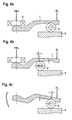
- the rocker arm actuator according to the invention as used for example as part of a clutch actuator or also be used in a transmission brake is installed in the preferred embodiment shown in Figures 1 and 2 such that a clutch (not shown) is pressed by means of an actuating lever 1 ,
- the actuating force or engaging force FE is shown in the form of an arrow on the left end of the actuating lever 1.
- the coupling is constructed in such a way that, when the electric motor (not shown) is not supplied with power, which is intended to drive a support roller 2, the clutch opens automatically and the actuating lever 1 pivots in the direction of the arrow FE.
- This so-called emergency strategy which opens the clutch in the event of a power failure, is designed to break the flow of power from an internal combustion engine through the clutch and a transmission to the drive wheels.
- this Kupplungsaktorik is also provided with a non-self-locking gear, which means that when a non-energization of the electric motor, the support roller. 2 as a result of a suitably designed rocking cam contour 4 moves into an exactly defined reference position.
- the electric motor is provided to drive the support roller 2 according to the embodiment in Figures 1 and 2 such that it is displaced from right to left and thus the fulcrum H is displaced accordingly.
- the support roller 2 is supported on a base plate 3 from.
- a load spring which introduces a spring force FL in the actuating lever 1 at the right end of the actuating lever 1, generates at the left end of the actuating lever 1 a lever force defined by the two lever arms, each with the longitudinal extension between H and FL and between H and FE the engagement force FE counteracts.
- the clutch is closed. Since the introduced spring force FL is constant, the leverage is changed by displacement of the fulcrum and the support roller 2 in height by the leverage is changed or the Hebelarmin be changed.
- the electric motor thus drives the support roller 2 from the position shown in Figure 2 and displaces the support roller 2, which may also consist of a double role or more roles, to the left in the figures.
- the ratio (length) of the two lever arms on the operating lever 1 is changed.
- the operating position of the clutch is shown.
- the introduced spring force FL is sufficiently large by means of the leverage to overcome the engagement force FE and close the clutch.
- the fulcrum is then H.
- the rocking cam contour 4 is selected so that a small restoring force or roller return force FR acts on the support roller 2 when the electric motor is not energized and due to the engagement force FE, which moves this support roller 2 to the right into a reference position.
- the rocking contour 4 must be designed so that in the reference position a stable contact of the support roller 2 is achieved. This situation is indicated in Figure 2 by the two arrows at H. At the two arrows, the surfaces of the Wippkurvenkontur 4 tangent to the surface of the support roller 2 in the respective point of contact. An equilibrium of forces occurs which positions and supports the support roller 2 at this position.
- the amount of the return force FR can be adjusted. In the region of the reference position, it is desirable for the return force FR to be slightly greater than in the remaining travel range of the support roller 2 in order to ensure a secure and permanently repeatable positioning in the reference or zero point.
- a flat rocking cam contour 4 has the advantage that a small restoring force FR is generated and thus a lower load on the electric motor is associated with an active driving of the support roller 2 against the rocking cam contour 4.
- the electric motor can therefore be designed weaker, smaller and cheaper.
- For the normal actuator operation only one direction of movement is actively used, ie. h., That a coupling between the electric motor and the support roller 2 and a displacement unit of the support rollers is loaded only in one direction of force. Accordingly, this coupling can be formed as a simple pluggable connection. A simple installation of such a pluggable connection is the positive result.
- a support roller 2 is provided to form the fulcrum H of the operating lever 1.
- multiple roles or equivalent devices may be provided instead of the support roller 2.
- the inventive type of referencing is simple in construction and easy to control. Both the targeted power cut on the electric motor and the non-energization of the electric motor in exceptional cases causes the rocker arm actuator automatically moves into the reference position and in a subsequent commissioning or recommissioning of the clutch actuator is a referencing or a zero point adjustment.
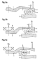
- FIG. 4 shows the functional principle of a rocking lever actuator, wherein a preloaded load spring acts on an actuating lever 1 and generates the force FL there.
- a support roller 2 results in a translation (lever lengths left and right of the fulcrum), which causes an associated force FKu on an engagement bearing 5 of the clutch. This situation is shown in FIG. 4a).
- the support roller 2 can move between the positions shown in Figures 4a) and 4b).
- rocking lever actuator is not designed to be self-locking, then the roller system may inadvertently move into the corresponding end position. If now an uncontrolled movement of the support rollers 2 occurs (not self-locking), so a high speed and consequently a significant shock in the final position of the actuator drive is to be feared.
- the unintentional displacement of the roller system 6 or the support roller 2 can be prevented automatically and with different embodiments according to the invention.
- FIG 5 such an embodiment is shown.
- FIG. 5 a the actuating lever 1 is locked by means of a catch 7 in such a way that pivoting about the fulcrum defined by the point of contact between the supporting roller 2 and the rocking cam is no longer possible.
- FIG. 5b the state is shown when the lock 7 is open and the operating lever 1 is in the installed position and is loaded by the engagement bearing 5 of the clutch (not shown) with the coupling reaction force FKu.
- FIG. 5c) shows a state analogous to FIG. 5b), wherein the support roller 2 or the roller system 6 is displaced to the left along the rocking curve. In all states, the spring force FL of the load spring on the right end of the actuating lever. 1
- the operation lever 1 pivots to the position shown in Fig. 5a).
- the spring force FL of the load spring pushes down the operating lever 1 on the right side of the fulcrum. Since the rocking curve then has a contour rising to the left (indicated by the angle arrows), the roller system 6 or the support roller 2 would run to the left without a safety device. This is prevented by the transport and / or assembly securing device according to the invention, which is designed in the form of a lock 7 in the present embodiment.
- the lock 7 locks the right end of the operating lever 1 with the roller system 6 such that movement of the roller system 6 and thus the support roller 2 is prevented.
- the roller system 6 runs on the base plate. 3
- the rocking curve on the actuating lever 1 is designed in such a way that the roller system 6 is loaded to the right, that is, a return force FR acting on the support roller (s) 2 in the entire working or swiveling range of the actuating lever 1 acts.
- a lock 7 is provided between the operating lever 1 and a cross member of the roller system 6 of the support roller 2. There are no additional components required, provided a hook-shaped engagement is guaranteed.
- a locking mechanism (not shown) can also be located on the base plate 3, which is actuated by the actuating lever 1.
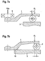
- FIG. 6a A further embodiment of the transport and / or assembly securing device according to the invention is shown in FIG.
- a stop 8 is provided as a backup, which prevents (further) pivoting of the actuating lever 1 in the direction of the arrow (left) in the figure 6a).
- the general structure of the Wipphebelaktors is identical to that of the figure 5.
- the transport or assembly position is shown, d. h., Without an effective coupling counterforce FKu, since the engagement bearing 5 is not yet applied against the left end of the actuating lever 1 and presses.
- the operating lever 1 Due to the spring force FL by the load spring (not shown), the operating lever 1 is pressed down on the right side of the fulcrum and comes with a nose-shaped extension, the stop 8 on the base plate 3, which may have a certain increase in this area to rest.
- a return force FR which loads the roller system 6 and the support roller 2 to the right, so that a stable position is formed, which prevents pivoting of the actuating lever 1.
- the stopper is formed at the rear, right end.
- this stop mechanism can also provide in the front region of the actuating lever 1, in which case a reverse force direction must be supported (on the other side of the fulcrum).
- An advantage of this alternative is that under certain circumstances no extension of the actuating lever 1 behind or above the reference position (zero point position of the drive) is required, so that a space savings results. Furthermore, by the occurring in the front region of the actuating lever larger ways when panning a lower tolerance sensitivity of the lever lock to record.
- FIG. 7a Another embodiment according to the present invention is shown in FIG. In Figure 7a), the operating position of the actuating lever 1 is shown, wherein a engagement bearing 5 of a clutch applies a coupling counterforce FKu on the left end of the actuating lever 1, while acting on the right end of the actuating lever 1, the spring force FL of the load spring.
- the support roller 2 is movable on the base plate 3 along the rocking curve in the working area; in FIG. 7 a), the position on the rightmost possible position along the rocking curve in the working area is shown.
- the rocking curve is designed such that a return force FR acts on the support roller (s) 2 in the entire working or travel range of the support roller 2, which causes a shift to the right.
- the support roller 2 by means of an electric motor drive (not shown) are moved to the left and thereby pivot the operating lever 1 in a clockwise direction about the also displaced to the left fulcrum to open the clutch, for example.
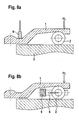
- FIG. 9 A further embodiment of the transport and / or assembly securing device according to the invention is shown in FIG.
- an additional locking element 9 is preferably used, which prevents pivoting of the actuating lever 1, provided that it is in the transport position.
- this blocking element 9 is inserted or installed against the actuating lever 1, so that the spring force FL acting on the right end of the actuating lever 1 can not pivot the actuating lever 1 further, despite the absence of coupling reaction force.
- the locking element 9 causes the load of the actuating lever 1 with a force FSperre. A movement of the support roller 2 and the traverse of the roller system is then excluded. After assembly of the coupling, the locking element 9 can be taken out or disassembled and the operating lever 1 can be pivoted in the work area.
- this blocking element 9 is used to act against the traverse of the roller system 6 of the support roller 2, so that the method of the support roller 2 is reliably prevented in any position of the actuating lever 1. After mounting the clutch, this locking element 9 can be removed. Also in the case of the embodiment according to FIG 8b) pivoting of the actuating lever 1 is prevented without acting counter-coupling force but with acting spring force FL of the load spring.
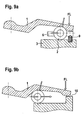
- FIG. 9 shows two further alternative embodiments according to the present invention.
- FIG. 9 a shows a blocking element 9 in the form of a spring-loaded detent ball, which engages in a corresponding depression on the traverse of the roller system 6.
- the support roller 2 In any (pivot) position of the actuating lever 1 and an applied spring force FL of the load spring, but missing coupling counterforce, the support roller 2 is fixed so that the spring force FL the operating lever 1 charged so that a stable mounting or transport position is taken. Only when a certain propulsion force (see arrow) by the electric motor drive (not shown), which acts on the support roller 2, is exceeded, the detent ball of the locking element 9 snaps out of the depression on the traverse and the support roller 2 can move in the work area.
Landscapes
- Engineering & Computer Science (AREA)
- General Engineering & Computer Science (AREA)
- Mechanical Engineering (AREA)
- Transmission Devices (AREA)
- Valve Device For Special Equipments (AREA)
- Mechanical Operated Clutches (AREA)
- Lock And Its Accessories (AREA)
Applications Claiming Priority (1)
| Application Number | Priority Date | Filing Date | Title |
|---|---|---|---|
| DE102005019792 | 2005-04-28 |
Publications (2)
| Publication Number | Publication Date |
|---|---|
| EP1744076A1 true EP1744076A1 (fr) | 2007-01-17 |
| EP1744076B1 EP1744076B1 (fr) | 2009-12-16 |
Family
ID=37311393
Family Applications (1)
| Application Number | Title | Priority Date | Filing Date |
|---|---|---|---|
| EP06007187A Expired - Lifetime EP1744076B1 (fr) | 2005-04-28 | 2006-04-05 | Dispositif de commande avec un levier balancant, en particulier pour un embrayage |
Country Status (3)
| Country | Link |
|---|---|
| EP (1) | EP1744076B1 (fr) |
| AT (1) | ATE452301T1 (fr) |
| DE (1) | DE502006005639D1 (fr) |
Cited By (3)
| Publication number | Priority date | Publication date | Assignee | Title |
|---|---|---|---|---|
| WO2011050768A1 (fr) * | 2009-10-26 | 2011-05-05 | Schaeffler Technologies Gmbh & Co. Kg | Dispositif d'actionnement pour embrayages |
| CN101581341B (zh) * | 2008-03-06 | 2012-08-08 | 格特拉格传动机构和齿轮工厂赫尔曼·哈根迈尔有限公司&两合公司 | 用于接合和脱开分离式离合器的具有可旋转凸轮部件的致动机构 |
| CN112443589A (zh) * | 2019-08-30 | 2021-03-05 | 比亚迪股份有限公司 | 离合器控制机构及车辆 |
Citations (4)
| Publication number | Priority date | Publication date | Assignee | Title |
|---|---|---|---|---|
| GB2205369A (en) * | 1987-06-05 | 1988-12-07 | Teves Gmbh Alfred | Braking pressure modulator |
| WO2001044677A1 (fr) * | 1998-12-17 | 2001-06-21 | Wabco Gmbh | Dispositif appliquant une force et frein pourvu de ce dispositif |
| WO2003016745A2 (fr) * | 2001-08-16 | 2003-02-27 | Wabco Gmbh & Co.Ohg | Dispositif de serrage d'un frein |
| EP1455106A1 (fr) * | 2003-03-03 | 2004-09-08 | LuK Lamellen und Kupplungsbau Beteiligungs KG | Systéme de débrayage |
-
2006
- 2006-04-05 AT AT06007187T patent/ATE452301T1/de active
- 2006-04-05 EP EP06007187A patent/EP1744076B1/fr not_active Expired - Lifetime
- 2006-04-05 DE DE502006005639T patent/DE502006005639D1/de not_active Expired - Lifetime
Patent Citations (5)
| Publication number | Priority date | Publication date | Assignee | Title |
|---|---|---|---|---|
| GB2205369A (en) * | 1987-06-05 | 1988-12-07 | Teves Gmbh Alfred | Braking pressure modulator |
| WO2001044677A1 (fr) * | 1998-12-17 | 2001-06-21 | Wabco Gmbh | Dispositif appliquant une force et frein pourvu de ce dispositif |
| WO2003016745A2 (fr) * | 2001-08-16 | 2003-02-27 | Wabco Gmbh & Co.Ohg | Dispositif de serrage d'un frein |
| EP1455106A1 (fr) * | 2003-03-03 | 2004-09-08 | LuK Lamellen und Kupplungsbau Beteiligungs KG | Systéme de débrayage |
| DE102004009832A1 (de) | 2003-03-03 | 2004-09-16 | Luk Lamellen Und Kupplungsbau Beteiligungs Kg | Ausrücksysteme |
Cited By (3)
| Publication number | Priority date | Publication date | Assignee | Title |
|---|---|---|---|---|
| CN101581341B (zh) * | 2008-03-06 | 2012-08-08 | 格特拉格传动机构和齿轮工厂赫尔曼·哈根迈尔有限公司&两合公司 | 用于接合和脱开分离式离合器的具有可旋转凸轮部件的致动机构 |
| WO2011050768A1 (fr) * | 2009-10-26 | 2011-05-05 | Schaeffler Technologies Gmbh & Co. Kg | Dispositif d'actionnement pour embrayages |
| CN112443589A (zh) * | 2019-08-30 | 2021-03-05 | 比亚迪股份有限公司 | 离合器控制机构及车辆 |
Also Published As
| Publication number | Publication date |
|---|---|
| EP1744076B1 (fr) | 2009-12-16 |
| DE502006005639D1 (de) | 2010-01-28 |
| ATE452301T1 (de) | 2010-01-15 |
Similar Documents
| Publication | Publication Date | Title |
|---|---|---|
| EP3691943B1 (fr) | Actionneur de frein mechanique | |
| DE102016207237B4 (de) | Aktuator zur Betätigung einer Kupplung eines Fahrzeugs | |
| DE102011014815A1 (de) | Kraftfahrzeugparksperrenvorrichtung mit zumindest einer Spindel | |
| EP2284345A1 (fr) | Dispositif de freinage pour un dispositif d'entraînement destiné au déplacement d'une porte et dispositif d'entraînement en étant équipé | |
| DE102015110186A1 (de) | Stellantrieb für eine Kupplung, insbesondere eines Kraftfahrzeugs | |
| DE69904110T2 (de) | Elektromagnetische Betätigungseinrichtung mit Gewindespindelantrieb | |
| EP3067591B1 (fr) | Ensemble de verrouillage de stationnement pour boîte de vitesses de véhicule automobile | |
| EP2005022B1 (fr) | Dispositif de freinage comprenant un accumulateur d'énergie élastique | |
| WO2011003877A1 (fr) | Servofrein électromécanique et système de freinage | |
| EP3077691B1 (fr) | Organe de commande pour actionner un actionneur hydraulique d'embrayage et embrayage à commande électrique | |
| DE102014223037A1 (de) | Parksperrenaktuator für eine Parksperre eines Kraftfahrzeug-Automatgetriebes | |
| DE202018106497U1 (de) | Parksperreneinheit | |
| EP3698071A1 (fr) | Dispositif d'actionnement d'un frein de stationnement d'un véhicule automobile | |
| EP3165419B1 (fr) | Frein d`inertie pour remorque | |
| EP2022688A2 (fr) | Système de freinage supplémentaire et dispositif de déclenchement pour systèmes de freinage supplémentaires pour l'actionnement de freins de remorques à inertie | |
| EP1744076B1 (fr) | Dispositif de commande avec un levier balancant, en particulier pour un embrayage | |
| DE102013214188B4 (de) | Vorrichtung zum Betätigen eines Verriegelungsmechanismus, insbesondere zum Betätigen einer Parksperreneinrichtung | |
| EP1952043B1 (fr) | Frein electromecanique sans jeu | |
| EP3077690A1 (fr) | Dispositif pour actionner un vérin hydraulique d'un embrayage à commande électrique de véhicule à moteur | |
| DE102019207075B3 (de) | Parksperrensystem | |
| WO2011003873A1 (fr) | Amplificateur de force de freinage électromécanique et système de freinage | |
| WO2012016639A1 (fr) | Servofrein électromécanique et système de freinage | |
| DE102008028265B4 (de) | Nachstellvorrichtung für eine Scheibenbremse | |
| DE102006015885A1 (de) | Wipphebelaktor, insbesondere zur Betätigung einer Kupplung | |
| EP1771325B1 (fr) | Dispositif de réglage pour un frein de stationnement |
Legal Events
| Date | Code | Title | Description |
|---|---|---|---|
| PUAI | Public reference made under article 153(3) epc to a published international application that has entered the european phase |
Free format text: ORIGINAL CODE: 0009012 |
|
| AK | Designated contracting states |
Kind code of ref document: A1 Designated state(s): AT BE BG CH CY CZ DE DK EE ES FI FR GB GR HU IE IS IT LI LT LU LV MC NL PL PT RO SE SI SK TR |
|
| AX | Request for extension of the european patent |
Extension state: AL BA HR MK YU |
|
| 17P | Request for examination filed |
Effective date: 20070717 |
|
| 17Q | First examination report despatched |
Effective date: 20070817 |
|
| AKX | Designation fees paid |
Designated state(s): AT BE BG CH CY CZ DE DK EE ES FI FR GB GR HU IE IS IT LI LT LU LV MC NL PL PT RO SE SI SK TR |
|
| GRAP | Despatch of communication of intention to grant a patent |
Free format text: ORIGINAL CODE: EPIDOSNIGR1 |
|
| GRAS | Grant fee paid |
Free format text: ORIGINAL CODE: EPIDOSNIGR3 |
|
| GRAA | (expected) grant |
Free format text: ORIGINAL CODE: 0009210 |
|
| AK | Designated contracting states |
Kind code of ref document: B1 Designated state(s): AT BE BG CH CY CZ DE DK EE ES FI FR GB GR HU IE IS IT LI LT LU LV MC NL PL PT RO SE SI SK TR |
|
| REG | Reference to a national code |
Ref country code: GB Ref legal event code: FG4D Free format text: NOT ENGLISH |
|
| REG | Reference to a national code |
Ref country code: CH Ref legal event code: EP |
|
| REG | Reference to a national code |
Ref country code: IE Ref legal event code: FG4D |
|
| REF | Corresponds to: |
Ref document number: 502006005639 Country of ref document: DE Date of ref document: 20100128 Kind code of ref document: P |
|
| REG | Reference to a national code |
Ref country code: NL Ref legal event code: VDEP Effective date: 20091216 |
|
| PG25 | Lapsed in a contracting state [announced via postgrant information from national office to epo] |
Ref country code: FI Free format text: LAPSE BECAUSE OF FAILURE TO SUBMIT A TRANSLATION OF THE DESCRIPTION OR TO PAY THE FEE WITHIN THE PRESCRIBED TIME-LIMIT Effective date: 20091216 Ref country code: LT Free format text: LAPSE BECAUSE OF FAILURE TO SUBMIT A TRANSLATION OF THE DESCRIPTION OR TO PAY THE FEE WITHIN THE PRESCRIBED TIME-LIMIT Effective date: 20091216 Ref country code: SE Free format text: LAPSE BECAUSE OF FAILURE TO SUBMIT A TRANSLATION OF THE DESCRIPTION OR TO PAY THE FEE WITHIN THE PRESCRIBED TIME-LIMIT Effective date: 20091216 |
|
| LTIE | Lt: invalidation of european patent or patent extension |
Effective date: 20091216 |
|
| PG25 | Lapsed in a contracting state [announced via postgrant information from national office to epo] |
Ref country code: SI Free format text: LAPSE BECAUSE OF FAILURE TO SUBMIT A TRANSLATION OF THE DESCRIPTION OR TO PAY THE FEE WITHIN THE PRESCRIBED TIME-LIMIT Effective date: 20091216 Ref country code: PL Free format text: LAPSE BECAUSE OF FAILURE TO SUBMIT A TRANSLATION OF THE DESCRIPTION OR TO PAY THE FEE WITHIN THE PRESCRIBED TIME-LIMIT Effective date: 20091216 Ref country code: LV Free format text: LAPSE BECAUSE OF FAILURE TO SUBMIT A TRANSLATION OF THE DESCRIPTION OR TO PAY THE FEE WITHIN THE PRESCRIBED TIME-LIMIT Effective date: 20091216 |
|
| REG | Reference to a national code |
Ref country code: IE Ref legal event code: FD4D |
|
| PG25 | Lapsed in a contracting state [announced via postgrant information from national office to epo] |
Ref country code: EE Free format text: LAPSE BECAUSE OF FAILURE TO SUBMIT A TRANSLATION OF THE DESCRIPTION OR TO PAY THE FEE WITHIN THE PRESCRIBED TIME-LIMIT Effective date: 20091216 Ref country code: IE Free format text: LAPSE BECAUSE OF FAILURE TO SUBMIT A TRANSLATION OF THE DESCRIPTION OR TO PAY THE FEE WITHIN THE PRESCRIBED TIME-LIMIT Effective date: 20091216 Ref country code: IS Free format text: LAPSE BECAUSE OF FAILURE TO SUBMIT A TRANSLATION OF THE DESCRIPTION OR TO PAY THE FEE WITHIN THE PRESCRIBED TIME-LIMIT Effective date: 20100416 Ref country code: RO Free format text: LAPSE BECAUSE OF FAILURE TO SUBMIT A TRANSLATION OF THE DESCRIPTION OR TO PAY THE FEE WITHIN THE PRESCRIBED TIME-LIMIT Effective date: 20091216 Ref country code: BG Free format text: LAPSE BECAUSE OF FAILURE TO SUBMIT A TRANSLATION OF THE DESCRIPTION OR TO PAY THE FEE WITHIN THE PRESCRIBED TIME-LIMIT Effective date: 20100316 Ref country code: ES Free format text: LAPSE BECAUSE OF FAILURE TO SUBMIT A TRANSLATION OF THE DESCRIPTION OR TO PAY THE FEE WITHIN THE PRESCRIBED TIME-LIMIT Effective date: 20100327 Ref country code: PT Free format text: LAPSE BECAUSE OF FAILURE TO SUBMIT A TRANSLATION OF THE DESCRIPTION OR TO PAY THE FEE WITHIN THE PRESCRIBED TIME-LIMIT Effective date: 20100416 Ref country code: NL Free format text: LAPSE BECAUSE OF FAILURE TO SUBMIT A TRANSLATION OF THE DESCRIPTION OR TO PAY THE FEE WITHIN THE PRESCRIBED TIME-LIMIT Effective date: 20091216 |
|
| PG25 | Lapsed in a contracting state [announced via postgrant information from national office to epo] |
Ref country code: SK Free format text: LAPSE BECAUSE OF FAILURE TO SUBMIT A TRANSLATION OF THE DESCRIPTION OR TO PAY THE FEE WITHIN THE PRESCRIBED TIME-LIMIT Effective date: 20091216 Ref country code: CZ Free format text: LAPSE BECAUSE OF FAILURE TO SUBMIT A TRANSLATION OF THE DESCRIPTION OR TO PAY THE FEE WITHIN THE PRESCRIBED TIME-LIMIT Effective date: 20091216 |
|
| RAP2 | Party data changed (patent owner data changed or rights of a patent transferred) |
Owner name: SCHAEFFLER TECHNOLOGIES GMBH & CO. KG |
|
| PLBE | No opposition filed within time limit |
Free format text: ORIGINAL CODE: 0009261 |
|
| STAA | Information on the status of an ep patent application or granted ep patent |
Free format text: STATUS: NO OPPOSITION FILED WITHIN TIME LIMIT |
|
| PG25 | Lapsed in a contracting state [announced via postgrant information from national office to epo] |
Ref country code: GR Free format text: LAPSE BECAUSE OF FAILURE TO SUBMIT A TRANSLATION OF THE DESCRIPTION OR TO PAY THE FEE WITHIN THE PRESCRIBED TIME-LIMIT Effective date: 20100317 Ref country code: CY Free format text: LAPSE BECAUSE OF FAILURE TO SUBMIT A TRANSLATION OF THE DESCRIPTION OR TO PAY THE FEE WITHIN THE PRESCRIBED TIME-LIMIT Effective date: 20091216 |
|
| BERE | Be: lapsed |
Owner name: LUK LAMELLEN UND KUPPLUNGSBAU BETEILIGUNGS K.G. Effective date: 20100430 |
|
| 26N | No opposition filed |
Effective date: 20100917 |
|
| PG25 | Lapsed in a contracting state [announced via postgrant information from national office to epo] |
Ref country code: MC Free format text: LAPSE BECAUSE OF NON-PAYMENT OF DUE FEES Effective date: 20100430 |
|
| REG | Reference to a national code |
Ref country code: CH Ref legal event code: PL |
|
| GBPC | Gb: european patent ceased through non-payment of renewal fee |
Effective date: 20100405 |
|
| PG25 | Lapsed in a contracting state [announced via postgrant information from national office to epo] |
Ref country code: DK Free format text: LAPSE BECAUSE OF FAILURE TO SUBMIT A TRANSLATION OF THE DESCRIPTION OR TO PAY THE FEE WITHIN THE PRESCRIBED TIME-LIMIT Effective date: 20091216 |
|
| PG25 | Lapsed in a contracting state [announced via postgrant information from national office to epo] |
Ref country code: CH Free format text: LAPSE BECAUSE OF NON-PAYMENT OF DUE FEES Effective date: 20100430 Ref country code: LI Free format text: LAPSE BECAUSE OF NON-PAYMENT OF DUE FEES Effective date: 20100430 |
|
| PG25 | Lapsed in a contracting state [announced via postgrant information from national office to epo] |
Ref country code: GB Free format text: LAPSE BECAUSE OF NON-PAYMENT OF DUE FEES Effective date: 20100405 Ref country code: BE Free format text: LAPSE BECAUSE OF NON-PAYMENT OF DUE FEES Effective date: 20100430 Ref country code: IT Free format text: LAPSE BECAUSE OF FAILURE TO SUBMIT A TRANSLATION OF THE DESCRIPTION OR TO PAY THE FEE WITHIN THE PRESCRIBED TIME-LIMIT Effective date: 20091216 |
|
| PG25 | Lapsed in a contracting state [announced via postgrant information from national office to epo] |
Ref country code: HU Free format text: LAPSE BECAUSE OF FAILURE TO SUBMIT A TRANSLATION OF THE DESCRIPTION OR TO PAY THE FEE WITHIN THE PRESCRIBED TIME-LIMIT Effective date: 20100617 Ref country code: LU Free format text: LAPSE BECAUSE OF NON-PAYMENT OF DUE FEES Effective date: 20100405 |
|
| REG | Reference to a national code |
Ref country code: DE Ref legal event code: R081 Ref document number: 502006005639 Country of ref document: DE Owner name: SCHAEFFLER TECHNOLOGIES AG & CO. KG, DE Free format text: FORMER OWNER: SCHAEFFLER TECHNOLOGIES GMBH & CO. KG, 91074 HERZOGENAURACH, DE Effective date: 20120828 Ref country code: DE Ref legal event code: R081 Ref document number: 502006005639 Country of ref document: DE Owner name: SCHAEFFLER TECHNOLOGIES GMBH & CO. KG, DE Free format text: FORMER OWNER: SCHAEFFLER TECHNOLOGIES GMBH & CO. KG, 91074 HERZOGENAURACH, DE Effective date: 20120828 |
|
| PG25 | Lapsed in a contracting state [announced via postgrant information from national office to epo] |
Ref country code: TR Free format text: LAPSE BECAUSE OF FAILURE TO SUBMIT A TRANSLATION OF THE DESCRIPTION OR TO PAY THE FEE WITHIN THE PRESCRIBED TIME-LIMIT Effective date: 20091216 |
|
| REG | Reference to a national code |
Ref country code: AT Ref legal event code: MM01 Ref document number: 452301 Country of ref document: AT Kind code of ref document: T Effective date: 20110405 |
|
| PG25 | Lapsed in a contracting state [announced via postgrant information from national office to epo] |
Ref country code: AT Free format text: LAPSE BECAUSE OF NON-PAYMENT OF DUE FEES Effective date: 20110405 |
|
| REG | Reference to a national code |
Ref country code: DE Ref legal event code: R081 Ref document number: 502006005639 Country of ref document: DE Owner name: SCHAEFFLER TECHNOLOGIES AG & CO. KG, DE Free format text: FORMER OWNER: SCHAEFFLER TECHNOLOGIES AG & CO. KG, 91074 HERZOGENAURACH, DE Effective date: 20140218 Ref country code: DE Ref legal event code: R081 Ref document number: 502006005639 Country of ref document: DE Owner name: SCHAEFFLER TECHNOLOGIES GMBH & CO. KG, DE Free format text: FORMER OWNER: SCHAEFFLER TECHNOLOGIES AG & CO. KG, 91074 HERZOGENAURACH, DE Effective date: 20140218 |
|
| REG | Reference to a national code |
Ref country code: DE Ref legal event code: R081 Ref document number: 502006005639 Country of ref document: DE Owner name: SCHAEFFLER TECHNOLOGIES AG & CO. KG, DE Free format text: FORMER OWNER: SCHAEFFLER TECHNOLOGIES GMBH & CO. KG, 91074 HERZOGENAURACH, DE Effective date: 20150213 |
|
| REG | Reference to a national code |
Ref country code: FR Ref legal event code: PLFP Year of fee payment: 11 |
|
| REG | Reference to a national code |
Ref country code: FR Ref legal event code: PLFP Year of fee payment: 12 |
|
| PGFP | Annual fee paid to national office [announced via postgrant information from national office to epo] |
Ref country code: DE Payment date: 20170630 Year of fee payment: 12 |
|
| REG | Reference to a national code |
Ref country code: FR Ref legal event code: PLFP Year of fee payment: 13 |
|
| PGFP | Annual fee paid to national office [announced via postgrant information from national office to epo] |
Ref country code: FR Payment date: 20180502 Year of fee payment: 13 |
|
| REG | Reference to a national code |
Ref country code: DE Ref legal event code: R119 Ref document number: 502006005639 Country of ref document: DE |
|
| PG25 | Lapsed in a contracting state [announced via postgrant information from national office to epo] |
Ref country code: DE Free format text: LAPSE BECAUSE OF NON-PAYMENT OF DUE FEES Effective date: 20181101 |
|
| PG25 | Lapsed in a contracting state [announced via postgrant information from national office to epo] |
Ref country code: FR Free format text: LAPSE BECAUSE OF NON-PAYMENT OF DUE FEES Effective date: 20190430 |
|
| P01 | Opt-out of the competence of the unified patent court (upc) registered |
Effective date: 20230523 |