EP1744100A2 - Chambre de combustion pour un brûleur à évaporation - Google Patents
Chambre de combustion pour un brûleur à évaporation Download PDFInfo
- Publication number
- EP1744100A2 EP1744100A2 EP06010694A EP06010694A EP1744100A2 EP 1744100 A2 EP1744100 A2 EP 1744100A2 EP 06010694 A EP06010694 A EP 06010694A EP 06010694 A EP06010694 A EP 06010694A EP 1744100 A2 EP1744100 A2 EP 1744100A2
- Authority
- EP
- European Patent Office
- Prior art keywords
- shell
- combustion chamber
- support
- peripheral wall
- porous evaporator
- Prior art date
- Legal status (The legal status is an assumption and is not a legal conclusion. Google has not performed a legal analysis and makes no representation as to the accuracy of the status listed.)
- Granted
Links
Images
Classifications
-
- F—MECHANICAL ENGINEERING; LIGHTING; HEATING; WEAPONS; BLASTING
- F23—COMBUSTION APPARATUS; COMBUSTION PROCESSES
- F23D—BURNERS
- F23D3/00—Burners using capillary action
- F23D3/40—Burners using capillary action the capillary action taking place in one or more rigid porous bodies
Definitions
- the present invention relates to a combustor assembly for an evaporator burner, particularly for a vehicle heater, comprising a combustor shell having a bottom assembly carried on a housing member, the bottom assembly having a shell-like support for porous evaporator media disposed therein, the porous evaporator media covering a bottom portion of the shell-like support and extends into the region of a peripheral wall of the cup-like carrier.
- the liquid to be vaporized and via the porous evaporator medium is generally supplied by means of a fuel feed line, which opens into an opening region of the shell-like carrier and thus feeds the fuel into the region of the porous evaporator medium located there.
- a combustion chamber assembly for an evaporator burner in particular for a vehicle heater, comprising a combustion chamber housing with a floor assembly carried on a housing part, the floor assembly having a shell-like support for porous evaporator medium disposed therein porous evaporator medium covers a bottom region of the shell-like support and extends into the region of a peripheral wall of the shell-like support, wherein the shell-like support is supported in the region of its peripheral wall with respect to the housing part, wherein on the housing part, the peripheral wall of the shell-like support axially - with respect to a Longitudinal center axis of the combustion chamber housing - supporting, provided radially inwardly extending projection region and wherein between the projection region and the porous evaporator medium a is arranged on the outer edge region of the porous evaporator medium covering cover made of absorbent material.
- the liquid fuel leakage outer peripheral portion of the porous evaporator medium or the abutment portion thereof is covered with the peripheral wall of the cup-like carrier by the absorbent member cover member. This means that in the event that in This outer edge region or adjacent to the inside of the peripheral wall of the shell-like carrier liquid fuel will accumulate, this is absorbed by the absorbent cover and thus the risk of direct entry of the liquid fuel can be avoided in a combustion chamber.
- the covering element should also be of annular design.
- an absorbent material for such a cover is for example nonwoven material, preferably ceramic nonwoven or metal nonwoven, since such material has a certain deformability and thus can be inserted very easily and the occurrence of gaps between the projecting area and the porous evaporator medium.
- a combustion chamber assembly for a An evaporator burner in particular for a vehicle heater, comprising a combustion chamber housing with a bottom assembly carried on a housing part, the bottom assembly comprising a shell-like support for porous evaporator medium disposed therein, the porous evaporator medium covering a bottom region of the shell-like support and extending into the region of a peripheral wall the shell-like support extends, wherein the shell-like support is supported in the region of its peripheral wall with respect to the housing part, wherein the porous evaporator medium in adaptation to the shape of the shell-like carrier has a shell-like shape with a bottom region of the shell-like carrier covering the bottom region and one inside of the peripheral wall the shell-like carrier overlapping peripheral wall.
- the porous evaporator medium Since, of course, the porous evaporator medium is absorbent in these areas, it can absorb more fuel there and thus prevent the risk of leakage of fuel in liquid form in the direction of the combustion chamber. However, since the thickness especially of the bottom portion of the porous evaporator medium can be maintained within a common range, the area effective for receiving and passing liquid fuel through capillary action is not excessively increased, so that the combustor assembly is very fast both in the startup phase and shutdown on changed conditions at the Fuel supply reacts.
- peripheral wall of the porous evaporator medium substantially completely covers the inside of the peripheral wall of the shell-like carrier.
- porous evaporator medium with its circumferential wall and its bottom area is provided by a part.
- an ignition element is carried on the combustion chamber assembly, which at least partially into one of the shell-like carrier and the porous Evaporator medium bounded space engages.
- the combustion chamber assembly according to the invention of the two above-indicated design variants can furthermore be characterized by a fuel feed line, which opens offset into the shell-like support with respect to a longitudinal center axis of the combustion chamber housing.
- the housing part carries a circumferential wall of the combustion chamber housing.
- An electrically energizable heating element may be provided on the rear side of the shell-type carrier facing away from the porous evaporator medium in order to be able to heat the porous evaporator medium, in particular during the start phase, and thus to be able to obtain enhanced fuel evaporation.
- the present invention further relates to an evaporator burner with a combustion chamber assembly according to the invention.
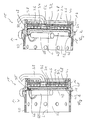
- a combustor assembly to be used in an evaporative burner of a vehicle heater is generally indicated at 10.
- This combustion chamber assembly 10 has a combustion chamber housing 14 with a substantially ring-like housing part 16.
- this housing part 16 carries a peripheral wall 20, which essentially surrounds a combustion chamber 22, by means of a ring-like and axially extending projection 18.
- the housing part 16 carries a generally designated 24 base assembly.
- This base assembly 24 comprises a shell-like carrier 26, which is formed, for example, from sheet material and has a substantially planar bottom region 28 and a circumferential wall 30.
- a heating element 32 designed as a heating spiral or spiral is provided on a rear side of the shell-like carrier 26 facing away from the combustion chamber 22 its back in turn is covered by an insulating layer 34 and a back plate 36.
- a fuel supply line 38 passes through the rear plate 36 and the insulating layer 34 and opens into a region of the shell-like carrier 26 that is offset with respect to a longitudinal center axis L.
- a porous evaporator medium 40th arranged in the cup-like carrier 26 .
- This has a planar, plate-like shape and is arranged and dimensioned so that it covers the bottom portion 28 of the shell-like carrier 26 substantially completely.
- the porous evaporator medium which may be made of nonwoven material, woven fabric, knitted fabric, foamed ceramic of the like, may be inserted into the shell-like support 26, but may also be sintered therein or have a solid bond to the bottom region 28.
- the porous evaporator medium 40 extends radially outward - with respect to the longitudinal center axis L - close to or directly to the peripheral wall 30, so that here either a contact contact is formed or possibly a small gap exists.
- FIG. 1 shows a cover element 46, which is preferably designed in the manner of a ring and completely encircling it. It lies between the projection area 42 and the outer edge area 48 of the porous evaporator medium 40.
- the annular cover element 46 is still located inside the shell-like support 26, ie it is preferably under pressure on the inside of the peripheral wall 30 thereof and thus extends between the outer edge region 48 of the porous evaporator medium 40 and the circumferential wall 30 existing space beyond the radially outer edge portion 48 of the porous evaporator medium 40 radially outward.
- the abutment area of the porous evaporator medium 40 is against the peripheral wall 30 of the shell-like carrier 26 covered by the cover 46.
- the circumferential wall 30 of the shell-like carrier 26 is dimensioned somewhat shorter so that it ends approximately flush with the surface of the porous evaporator medium 40 lying toward the combustion chamber 22.
- the annular cover member 46 is not only located between the projection portion 42 and this surface of the porous evaporator medium 40, but also the axial end face of the peripheral wall 30 and the projection portion 42. That is, there is no direct abutting contact between the peripheral wall 30 and the projection portion 42.
- the shell-like carrier 26 is supported in the radial direction by the peripheral wall 30 resting radially outward on the housing part 16.
- the peripheral wall 30 may be slightly conical, so that only a line contact with the housing part 16 is out.
- the cover element 46 of the combustion chamber assembly 10 shown in FIG. 1 is made of absorbent material, that is, for example, nonwoven material. It thus not only covers the outer edge region 48 of the porous evaporator medium 40, but also provides a suction effect in this region. Liquid fuel, which has moved due to the capillary action of the porous evaporator medium 40 and also under the influence of gravity in this outer edge region 48, thus can not escape via the possibly existing to the peripheral wall 30 intermediate space in the direction of the combustion chamber 22. Rather, by the suction effect of the cover 46 also such liquid fuel is sucked up again.
- the cover element 46 is held under pressure between the porous evaporator medium 40 and the projection region 42, so that both adjacent to the porous evaporator medium 40 and in abutment with the projection region 42 Intermediate spaces can be avoided.
- Fig. 1 further on the peripheral wall 20 and possibly also the housing part 16 of the combustion chamber housing 14 worn and approximately radially extending ignition device 50, such as Glühzündux.
- This elongate ignition device 50 is located at a small distance and preferably parallel to the surface of the porous evaporator medium 40 and serves to provide locally high enough temperatures in the starting phase to start the combustion.
- FIG. 2 an alternative embodiment of a combustion chamber assembly 10 according to the invention is shown. It can be seen here that in adaptation to the shell-like shape of the carrier 26 and the porous evaporator medium 40 is provided with such a shell shape. It has a bottom area 52 which substantially completely covers the bottom area 28 of the shell-like carrier 26 and a peripheral wall 54 which adjoins it radially and thus forms an inner wall of the peripheral wall 30 of the cup-like carrier 26 and is dimensioned such that it essentially ends flush with this one.
- the porous evaporator medium 40 is already provided with such a shell shape and is inserted into the shell-like carrier 26. Also, a substantially planar element can be fitted and thereby deformed accordingly. Of course, the sintering of such a porous evaporator medium 40 in the shell-like carrier 26 is possible.
- the adjoining area between the porous evaporator medium 40 and the circumferential wall 30 of the shell-like carrier 26 in the direction of the longitudinal center axis L is designed significantly longer than in the embodiment described above, in particular significantly longer than the axial thickness of the Bottom region 52 of the porous evaporator medium 40.
- Liquid fuel, possibly in the radially outer edge region 48 of the porous evaporator medium 40 accumulates increasingly, a significantly longer axial distance along the boundary region between the peripheral wall 44 of the porous evaporator medium 40 and the peripheral wall 30 of the shell-like carrier 26 must flow to move in the direction of the combustion chamber 22. Due to the suction effect of the porous evaporator medium 40, however, such fuel is sucked or held therein, so that the risk of leakage of liquid fuel in the direction of the combustion chamber 22 is virtually eliminated.
- porous evaporator medium 40 especially in the region of its peripheral wall 54, bears firmly against the inside of the circumferential wall 30 of the shell-like carrier 26, preferably fixed thereto, for example, by sintering or sintering.
- the ignition element 50 carried on the circumferential wall 20 or the housing part 16 is positioned such that it passes through a corresponding recess in the circumferential wall 30 of the shell-like support 26 and the peripheral wall 54 of the porous evaporator medium 40. engages in this and thus at least with a portion of its in the ignition chamber 22 extending portion in the bounded by the shell-like support 26 and the correspondingly shaped porous evaporator medium 40 space region, which of course provides a portion of the combustion chamber 22.
- fuel vapor will be increasingly present in the starting phase, which then can easily ignite after mixing with combustion air.
- the peripheral wall 20 could be connected to the housing part 16 be designed integrally.
- the basic structure of the base assembly with the heating element 32, the insulation 34 and the back plate 36 could be different.
- the fuel supply line could also open at a different position in the shell-like carrier, for example, also centrally to the longitudinal center axis L, or it could open several sections of the fuel supply 38 at different areas in the shell-like carrier 26.
Landscapes
- Engineering & Computer Science (AREA)
- Chemical & Material Sciences (AREA)
- Combustion & Propulsion (AREA)
- Mechanical Engineering (AREA)
- General Engineering & Computer Science (AREA)
- Wick-Type Burners And Burners With Porous Materials (AREA)
- Air-Conditioning For Vehicles (AREA)
Priority Applications (1)
| Application Number | Priority Date | Filing Date | Title |
|---|---|---|---|
| PL06010694T PL1744100T3 (pl) | 2005-07-14 | 2006-05-23 | Zespół komory spalania dla palnika odparowania |
Applications Claiming Priority (1)
| Application Number | Priority Date | Filing Date | Title |
|---|---|---|---|
| DE102005032980A DE102005032980B4 (de) | 2005-07-14 | 2005-07-14 | Brennkammerbaugruppe für einen Verdampferbrenner |
Publications (3)
| Publication Number | Publication Date |
|---|---|
| EP1744100A2 true EP1744100A2 (fr) | 2007-01-17 |
| EP1744100A3 EP1744100A3 (fr) | 2008-10-22 |
| EP1744100B1 EP1744100B1 (fr) | 2014-03-19 |
Family
ID=37036997
Family Applications (1)
| Application Number | Title | Priority Date | Filing Date |
|---|---|---|---|
| EP06010694.5A Active EP1744100B1 (fr) | 2005-07-14 | 2006-05-23 | Chambre de combustion pour un brûleur à évaporation |
Country Status (3)
| Country | Link |
|---|---|
| EP (1) | EP1744100B1 (fr) |
| DE (1) | DE102005032980B4 (fr) |
| PL (1) | PL1744100T3 (fr) |
Cited By (7)
| Publication number | Priority date | Publication date | Assignee | Title |
|---|---|---|---|---|
| EP2009352A3 (fr) * | 2007-06-25 | 2011-03-30 | J. Eberspächer GmbH & Co. KG | Composant d'évaporateur, en particulier pour un appareil de chauffage de véhicule |
| WO2013127390A3 (fr) * | 2012-02-27 | 2014-01-23 | Webasto SE | Brûleur à vaporisation avec élément de recouvrement pour appareil de chauffage mobile |
| US20150102115A1 (en) * | 2013-10-14 | 2015-04-16 | Eberspächer Climate Control Systems GmbH & Co. KG | Bottom assembly unit for a combustion chamber assembly unit of a vaporizing burner |
| US20150102116A1 (en) * | 2013-10-14 | 2015-04-16 | Eberspächer Climate Control Systems GmbH & Co. KG | Bottom assembly unit for a combustion chamber assembly unit of a vaporizing burner |
| US20180066841A1 (en) * | 2016-09-07 | 2018-03-08 | Eberspächer Climate Control Systems GmbH & Co. KG | Combustion chamber assembly unit for a vaporizing burner |
| US20180094806A1 (en) * | 2015-06-02 | 2018-04-05 | Sango Co., Ltd. | Evaporation type burner |
| US11198347B2 (en) * | 2017-12-22 | 2021-12-14 | Webasto SE | Evaporator unit for a fuel-operated vehicle heater |
Families Citing this family (6)
| Publication number | Priority date | Publication date | Assignee | Title |
|---|---|---|---|---|
| DE102009025593B4 (de) | 2009-06-19 | 2016-12-08 | Eberspächer Climate Control Systems GmbH & Co. KG | Verdampferbaugruppe für einen Verdampferbrenner, insbesondere eines Fahrzeugheizgerätes |
| DE102012211932B3 (de) * | 2012-07-09 | 2013-10-31 | Eberspächer Climate Control Systems GmbH & Co. KG | Brennkammerbaugruppe, insbesondere für ein Fahrzeugheizgerät |
| DE102013220652B4 (de) | 2013-10-14 | 2015-07-02 | Eberspächer Climate Control Systems GmbH & Co. KG | Brennkammerbaugruppe, insbesondere für einen Verdampferbrenner, insbesondere für ein Fahrzeugheizgerät |
| DE102013220653B4 (de) * | 2013-10-14 | 2019-12-05 | Eberspächer Climate Control Systems GmbH & Co. KG | Brennkammerbaugruppe, insbesondere für einen Verdampferbrenner |
| DE102020100403B4 (de) | 2020-01-10 | 2021-07-22 | Webasto SE | Brenner, mobile Heizvorrichtung und Verfahren |
| DE102020100402B4 (de) | 2020-01-10 | 2021-07-22 | Webasto SE | Brenner, mobile Heizvorrichtung und Verfahren zum Herstellen eines Brenners |
Citations (4)
| Publication number | Priority date | Publication date | Assignee | Title |
|---|---|---|---|---|
| DE3722093A1 (de) | 1986-07-08 | 1988-01-21 | Isuzu Motors Ltd | Brenner |
| DE4243712C1 (de) | 1991-12-14 | 1994-06-16 | Eberspaecher J | Heizgerät für Fahrzeuge, das mit flüssigem Brennstoff unabhängig von dem Motor des Fahrzeuges betreibbar ist |
| DE19546130A1 (de) | 1995-12-11 | 1997-06-12 | Webasto Thermosysteme Gmbh | Verdampfungsbrenner eines motorunabhängigen Fahrzeugheizgeräts |
| DE10252888B3 (de) | 2002-11-12 | 2004-01-29 | Webasto Thermosysteme International Gmbh | Verdampfungsbrenner für ein mit flüssigem Brennstoff betriebenes Heizgerät |
Family Cites Families (7)
| Publication number | Priority date | Publication date | Assignee | Title |
|---|---|---|---|---|
| DE3607574A1 (de) * | 1986-03-07 | 1987-09-10 | Rudolf Schreiner | Startvorrichtung fuer zusatzheizungen mit dochtbrennern |
| DE4134449A1 (de) * | 1990-10-23 | 1992-04-30 | Gerd Waschkuttis | Kaltstartbrenner |
| DE4118581A1 (de) * | 1991-06-06 | 1992-12-10 | Webasto Ag Fahrzeugtechnik | Heizgeraet, insbesondere fahrzeug-zusatzheizgeraet |
| DE4401799C1 (de) * | 1994-01-22 | 1995-06-14 | Webasto Thermosysteme Gmbh | Verdampfungsbrenner für ein Heizgerät |
| DE19507556B4 (de) * | 1994-10-20 | 2004-12-30 | J. Eberspächer GmbH & Co. KG | Verfahren zum Starten eines Brenners für ein Fahrzeugheizgerät oder einen Partikelfilter-Regenerator |
| DE10251438C5 (de) * | 2002-11-05 | 2009-06-18 | J. Eberspächer GmbH & Co. KG | Verdampferbrenner, insbesondere für ein Heizgerät |
| DE10343282B3 (de) * | 2003-09-18 | 2005-04-21 | J. Eberspächer GmbH & Co. KG | Brenneranordnung, insbesondere für ein Fahrzeugheizgerät |
-
2005
- 2005-07-14 DE DE102005032980A patent/DE102005032980B4/de not_active Expired - Fee Related
-
2006
- 2006-05-23 EP EP06010694.5A patent/EP1744100B1/fr active Active
- 2006-05-23 PL PL06010694T patent/PL1744100T3/pl unknown
Patent Citations (4)
| Publication number | Priority date | Publication date | Assignee | Title |
|---|---|---|---|---|
| DE3722093A1 (de) | 1986-07-08 | 1988-01-21 | Isuzu Motors Ltd | Brenner |
| DE4243712C1 (de) | 1991-12-14 | 1994-06-16 | Eberspaecher J | Heizgerät für Fahrzeuge, das mit flüssigem Brennstoff unabhängig von dem Motor des Fahrzeuges betreibbar ist |
| DE19546130A1 (de) | 1995-12-11 | 1997-06-12 | Webasto Thermosysteme Gmbh | Verdampfungsbrenner eines motorunabhängigen Fahrzeugheizgeräts |
| DE10252888B3 (de) | 2002-11-12 | 2004-01-29 | Webasto Thermosysteme International Gmbh | Verdampfungsbrenner für ein mit flüssigem Brennstoff betriebenes Heizgerät |
Cited By (12)
| Publication number | Priority date | Publication date | Assignee | Title |
|---|---|---|---|---|
| EP2009352A3 (fr) * | 2007-06-25 | 2011-03-30 | J. Eberspächer GmbH & Co. KG | Composant d'évaporateur, en particulier pour un appareil de chauffage de véhicule |
| WO2013127390A3 (fr) * | 2012-02-27 | 2014-01-23 | Webasto SE | Brûleur à vaporisation avec élément de recouvrement pour appareil de chauffage mobile |
| US20150102115A1 (en) * | 2013-10-14 | 2015-04-16 | Eberspächer Climate Control Systems GmbH & Co. KG | Bottom assembly unit for a combustion chamber assembly unit of a vaporizing burner |
| US20150102116A1 (en) * | 2013-10-14 | 2015-04-16 | Eberspächer Climate Control Systems GmbH & Co. KG | Bottom assembly unit for a combustion chamber assembly unit of a vaporizing burner |
| CN104566360A (zh) * | 2013-10-14 | 2015-04-29 | 埃贝斯佩歇气候控制系统有限责任两合公司 | 用于蒸发器燃烧炉的燃烧室组件的底板组件 |
| CN104566360B (zh) * | 2013-10-14 | 2017-08-29 | 埃贝斯佩歇气候控制系统有限责任两合公司 | 用于蒸发器燃烧炉的燃烧室组件的底板组件 |
| US9857081B2 (en) | 2013-10-14 | 2018-01-02 | Eberspächer Climate Control Systems GmbH & Co. KG | Bottom assembly unit for a combustion chamber assembly unit of a vaporizing burner |
| US9863640B2 (en) * | 2013-10-14 | 2018-01-09 | Eberspächer Climate Control Systems GmbH & Co. KG | Bottom assembly unit for a combustion chamber assembly unit of a vaporizing burner |
| US20180094806A1 (en) * | 2015-06-02 | 2018-04-05 | Sango Co., Ltd. | Evaporation type burner |
| US20180066841A1 (en) * | 2016-09-07 | 2018-03-08 | Eberspächer Climate Control Systems GmbH & Co. KG | Combustion chamber assembly unit for a vaporizing burner |
| US10571119B2 (en) * | 2016-09-07 | 2020-02-25 | Eberspächer Climate Control Systems GmbH & Co. KG | Combustion chamber assembly unit for a vaporizing burner |
| US11198347B2 (en) * | 2017-12-22 | 2021-12-14 | Webasto SE | Evaporator unit for a fuel-operated vehicle heater |
Also Published As
| Publication number | Publication date |
|---|---|
| DE102005032980A1 (de) | 2007-01-25 |
| EP1744100A3 (fr) | 2008-10-22 |
| PL1744100T3 (pl) | 2014-08-29 |
| EP1744100B1 (fr) | 2014-03-19 |
| DE102005032980B4 (de) | 2008-04-24 |
Similar Documents
| Publication | Publication Date | Title |
|---|---|---|
| EP1744100B1 (fr) | Chambre de combustion pour un brûleur à évaporation | |
| DE102013220655B4 (de) | Bodenbaugruppe für eine Brennkammerbaugruppe eines Verdampferbrenners | |
| DE102013220654B4 (de) | Brennkammerbaugruppe für einen Verdampferbrenner | |
| EP2607757B1 (fr) | Bague d'étanchéité glissante | |
| EP3296632B1 (fr) | Composant de chambre de combustion pour un appareil de chauffage à combustible pour un véhicule | |
| WO2001057446A1 (fr) | Appareil de chauffage, notamment systeme de chauffage de vehicule independant du moteur | |
| EP1574782A2 (fr) | Brûleur à évaporation, en particulier pour un dispositif de chauffage de voiture | |
| DE2361370A1 (de) | Vorrichtung zum abdaempfen von kompressor- oder turbinenschaufeln | |
| DE102008031083B4 (de) | Verdampferbaugruppe für einen Verdampferbrenner eines Heizgerätes, insbesondere für ein Fahrzeug | |
| DE10343282B3 (de) | Brenneranordnung, insbesondere für ein Fahrzeugheizgerät | |
| DE10325574A1 (de) | Brennkammeranordnung für einen Verdampferbrenner, insbesondere für ein Fahrzeugheizgerät | |
| DE10164225B4 (de) | Verdampfungsbrenner | |
| DE102009025593B4 (de) | Verdampferbaugruppe für einen Verdampferbrenner, insbesondere eines Fahrzeugheizgerätes | |
| DE3521058C2 (fr) | ||
| EP1464893B1 (fr) | Dispositif de brûleur pour un appareil de chauffe et appareil de chauffe, en particulier appareil de chauffe de véhicule | |
| EP1557611B1 (fr) | Joint d'étanchéité, revêtement et chambre de combustion | |
| EP1788305A1 (fr) | Ensemble de chambre de combustion pour un brûleur à évaporation | |
| DE102007030606A1 (de) | Fahrzeugheizgerät | |
| EP1342949A1 (fr) | Elément d'évaporateur d'un brûleur à vaporisation | |
| EP4431804B1 (fr) | Ensemble chambre de combustion pour brûleur à vaporisation | |
| EP1717517A2 (fr) | Evaporateur, en particulier pour un dispositif de chauffage de voiture ou pour un réformeur | |
| DE2407263A1 (de) | Einrichtung zur katalytischen abgasreinigung | |
| EP1927488B2 (fr) | Appareil de chauffage pour véhicule | |
| DE10323899B3 (de) | Brennkammeranordnung | |
| DE102011051044B3 (de) | Brennkammeranordnung |
Legal Events
| Date | Code | Title | Description |
|---|---|---|---|
| PUAI | Public reference made under article 153(3) epc to a published international application that has entered the european phase |
Free format text: ORIGINAL CODE: 0009012 |
|
| AK | Designated contracting states |
Kind code of ref document: A2 Designated state(s): AT BE BG CH CY CZ DE DK EE ES FI FR GB GR HU IE IS IT LI LT LU LV MC NL PL PT RO SE SI SK TR |
|
| AX | Request for extension of the european patent |
Extension state: AL BA HR MK YU |
|
| PUAL | Search report despatched |
Free format text: ORIGINAL CODE: 0009013 |
|
| AK | Designated contracting states |
Kind code of ref document: A3 Designated state(s): AT BE BG CH CY CZ DE DK EE ES FI FR GB GR HU IE IS IT LI LT LU LV MC NL PL PT RO SE SI SK TR |
|
| AX | Request for extension of the european patent |
Extension state: AL BA HR MK YU |
|
| 17P | Request for examination filed |
Effective date: 20090422 |
|
| AKX | Designation fees paid |
Designated state(s): CZ DE PL SE |
|
| 17Q | First examination report despatched |
Effective date: 20090529 |
|
| RAP1 | Party data changed (applicant data changed or rights of an application transferred) |
Owner name: EBERSPAECHER CLIMATE CONTROL SYSTEMS GMBH & CO. KG |
|
| GRAP | Despatch of communication of intention to grant a patent |
Free format text: ORIGINAL CODE: EPIDOSNIGR1 |
|
| INTG | Intention to grant announced |
Effective date: 20131219 |
|
| GRAS | Grant fee paid |
Free format text: ORIGINAL CODE: EPIDOSNIGR3 |
|
| GRAA | (expected) grant |
Free format text: ORIGINAL CODE: 0009210 |
|
| AK | Designated contracting states |
Kind code of ref document: B1 Designated state(s): CZ DE PL SE |
|
| REG | Reference to a national code |
Ref country code: DE Ref legal event code: R096 Ref document number: 502006013603 Country of ref document: DE Effective date: 20140430 |
|
| REG | Reference to a national code |
Ref country code: SE Ref legal event code: TRGR |
|
| REG | Reference to a national code |
Ref country code: PL Ref legal event code: T3 |
|
| REG | Reference to a national code |
Ref country code: DE Ref legal event code: R082 Ref document number: 502006013603 Country of ref document: DE Representative=s name: RUTTENSPERGER LACHNIT TROSSIN GOMOLL PATENT- U, DE Ref country code: DE Ref legal event code: R082 Ref document number: 502006013603 Country of ref document: DE Representative=s name: RUTTENSPERGER LACHNIT TROSSIN GOMOLL, PATENT- , DE |
|
| REG | Reference to a national code |
Ref country code: DE Ref legal event code: R097 Ref document number: 502006013603 Country of ref document: DE |
|
| PLBE | No opposition filed within time limit |
Free format text: ORIGINAL CODE: 0009261 |
|
| STAA | Information on the status of an ep patent application or granted ep patent |
Free format text: STATUS: NO OPPOSITION FILED WITHIN TIME LIMIT |
|
| 26N | No opposition filed |
Effective date: 20141222 |
|
| REG | Reference to a national code |
Ref country code: DE Ref legal event code: R097 Ref document number: 502006013603 Country of ref document: DE Effective date: 20141222 |
|
| REG | Reference to a national code |
Ref country code: DE Ref legal event code: R082 Ref document number: 502006013603 Country of ref document: DE Representative=s name: RUTTENSPERGER LACHNIT TROSSIN GOMOLL, PATENT- , DE Ref country code: DE Ref legal event code: R081 Ref document number: 502006013603 Country of ref document: DE Owner name: EBERSPAECHER CLIMATE CONTROL SYSTEMS GMBH, DE Free format text: FORMER OWNER: EBERSPAECHER CLIMATE CONTROL SYSTEMS GMBH & CO. KG, 73730 ESSLINGEN, DE |
|
| PGFP | Annual fee paid to national office [announced via postgrant information from national office to epo] |
Ref country code: PL Payment date: 20250509 Year of fee payment: 20 Ref country code: DE Payment date: 20250531 Year of fee payment: 20 |
|
| PGFP | Annual fee paid to national office [announced via postgrant information from national office to epo] |
Ref country code: CZ Payment date: 20250509 Year of fee payment: 20 |
|
| PGFP | Annual fee paid to national office [announced via postgrant information from national office to epo] |
Ref country code: SE Payment date: 20250522 Year of fee payment: 20 |