EP1744170A1 - Kaltmassestruktur mit geringem Feldverlust für supraleitende Magneten - Google Patents
Kaltmassestruktur mit geringem Feldverlust für supraleitende Magneten Download PDFInfo
- Publication number
- EP1744170A1 EP1744170A1 EP06253559A EP06253559A EP1744170A1 EP 1744170 A1 EP1744170 A1 EP 1744170A1 EP 06253559 A EP06253559 A EP 06253559A EP 06253559 A EP06253559 A EP 06253559A EP 1744170 A1 EP1744170 A1 EP 1744170A1
- Authority
- EP
- European Patent Office
- Prior art keywords
- thermally conductive
- coil
- superconducting
- composite bobbin
- electrically resistive
- Prior art date
- Legal status (The legal status is an assumption and is not a legal conclusion. Google has not performed a legal analysis and makes no representation as to the accuracy of the status listed.)
- Ceased
Links
- 239000002131 composite material Substances 0.000 claims abstract description 74
- 239000012530 fluid Substances 0.000 claims abstract description 5
- 238000000034 method Methods 0.000 claims description 14
- 238000003384 imaging method Methods 0.000 claims description 7
- 239000011152 fibreglass Substances 0.000 claims description 5
- 238000004519 manufacturing process Methods 0.000 claims description 5
- 239000011810 insulating material Substances 0.000 claims description 2
- 238000004804 winding Methods 0.000 claims 1
- 238000002595 magnetic resonance imaging Methods 0.000 description 8
- 229910052751 metal Inorganic materials 0.000 description 8
- 239000002184 metal Substances 0.000 description 8
- 229910052734 helium Inorganic materials 0.000 description 6
- 239000001307 helium Substances 0.000 description 6
- SWQJXJOGLNCZEY-UHFFFAOYSA-N helium atom Chemical compound [He] SWQJXJOGLNCZEY-UHFFFAOYSA-N 0.000 description 6
- 239000000463 material Substances 0.000 description 5
- 238000001816 cooling Methods 0.000 description 4
- 239000004033 plastic Substances 0.000 description 4
- 238000004611 spectroscopical analysis Methods 0.000 description 4
- 229910052782 aluminium Inorganic materials 0.000 description 3
- XAGFODPZIPBFFR-UHFFFAOYSA-N aluminium Chemical compound [Al] XAGFODPZIPBFFR-UHFFFAOYSA-N 0.000 description 3
- 230000008878 coupling Effects 0.000 description 3
- 238000010168 coupling process Methods 0.000 description 3
- 238000005859 coupling reaction Methods 0.000 description 3
- 239000010935 stainless steel Substances 0.000 description 3
- 229910001220 stainless steel Inorganic materials 0.000 description 3
- 229910000975 Carbon steel Inorganic materials 0.000 description 2
- 239000004593 Epoxy Substances 0.000 description 2
- 239000010962 carbon steel Substances 0.000 description 2
- 239000000919 ceramic Substances 0.000 description 2
- 230000005669 field effect Effects 0.000 description 2
- 239000007788 liquid Substances 0.000 description 2
- 150000002739 metals Chemical class 0.000 description 2
- 238000004382 potting Methods 0.000 description 2
- RYGMFSIKBFXOCR-UHFFFAOYSA-N Copper Chemical compound [Cu] RYGMFSIKBFXOCR-UHFFFAOYSA-N 0.000 description 1
- 229910001275 Niobium-titanium Inorganic materials 0.000 description 1
- 238000007792 addition Methods 0.000 description 1
- WYTGDNHDOZPMIW-RCBQFDQVSA-N alstonine Natural products C1=CC2=C3C=CC=CC3=NC2=C2N1C[C@H]1[C@H](C)OC=C(C(=O)OC)[C@H]1C2 WYTGDNHDOZPMIW-RCBQFDQVSA-N 0.000 description 1
- 230000000712 assembly Effects 0.000 description 1
- 238000000429 assembly Methods 0.000 description 1
- 229910010293 ceramic material Inorganic materials 0.000 description 1
- 239000004020 conductor Substances 0.000 description 1
- 229910052802 copper Inorganic materials 0.000 description 1
- 239000010949 copper Substances 0.000 description 1
- 239000012777 electrically insulating material Substances 0.000 description 1
- 238000004146 energy storage Methods 0.000 description 1
- 239000000835 fiber Substances 0.000 description 1
- 239000002657 fibrous material Substances 0.000 description 1
- 238000002955 isolation Methods 0.000 description 1
- 238000012986 modification Methods 0.000 description 1
- 230000004048 modification Effects 0.000 description 1
- RJSRQTFBFAJJIL-UHFFFAOYSA-N niobium titanium Chemical compound [Ti].[Nb] RJSRQTFBFAJJIL-UHFFFAOYSA-N 0.000 description 1
- 238000005057 refrigeration Methods 0.000 description 1
- 238000003466 welding Methods 0.000 description 1
Images




Classifications
-
- H—ELECTRICITY
- H01—ELECTRIC ELEMENTS
- H01F—MAGNETS; INDUCTANCES; TRANSFORMERS; SELECTION OF MATERIALS FOR THEIR MAGNETIC PROPERTIES
- H01F6/00—Superconducting magnets; Superconducting coils
- H01F6/04—Cooling
-
- G—PHYSICS
- G01—MEASURING; TESTING
- G01R—MEASURING ELECTRIC VARIABLES; MEASURING MAGNETIC VARIABLES
- G01R33/00—Arrangements or instruments for measuring magnetic variables
- G01R33/20—Arrangements or instruments for measuring magnetic variables involving magnetic resonance
- G01R33/28—Details of apparatus provided for in groups G01R33/44 - G01R33/64
- G01R33/38—Systems for generation, homogenisation or stabilisation of the main or gradient magnetic field
- G01R33/381—Systems for generation, homogenisation or stabilisation of the main or gradient magnetic field using electromagnets
- G01R33/3815—Systems for generation, homogenisation or stabilisation of the main or gradient magnetic field using electromagnets with superconducting coils, e.g. power supply therefor
-
- H—ELECTRICITY
- H01—ELECTRIC ELEMENTS
- H01F—MAGNETS; INDUCTANCES; TRANSFORMERS; SELECTION OF MATERIALS FOR THEIR MAGNETIC PROPERTIES
- H01F5/00—Coils
- H01F5/04—Arrangements of electric connections to coils, e.g. leads
-
- H—ELECTRICITY
- H01—ELECTRIC ELEMENTS
- H01F—MAGNETS; INDUCTANCES; TRANSFORMERS; SELECTION OF MATERIALS FOR THEIR MAGNETIC PROPERTIES
- H01F27/00—Details of transformers or inductances, in general
- H01F27/08—Cooling; Ventilating
- H01F27/22—Cooling by heat conduction through solid or powdered fillings
-
- H—ELECTRICITY
- H01—ELECTRIC ELEMENTS
- H01F—MAGNETS; INDUCTANCES; TRANSFORMERS; SELECTION OF MATERIALS FOR THEIR MAGNETIC PROPERTIES
- H01F27/00—Details of transformers or inductances, in general
- H01F27/28—Coils; Windings; Conductive connections
- H01F27/2876—Cooling
-
- H—ELECTRICITY
- H01—ELECTRIC ELEMENTS
- H01F—MAGNETS; INDUCTANCES; TRANSFORMERS; SELECTION OF MATERIALS FOR THEIR MAGNETIC PROPERTIES
- H01F6/00—Superconducting magnets; Superconducting coils
Definitions
- the invention relates generally to superconducting magnets, and more particularly to a low-AC loss cold mass structure for superconducting magnets and a process for manufacturing the cold mass structure.
- MRI magnetic resonance imaging
- magnetic gradient coils and radio-frequency transmit and receive coils then influence gyromagnetic materials in the subject to provoke signals that can be used to form useful images.
- Other systems that use such coils include spectroscopy systems, magnetic energy storage systems, and superconducting generators.
- a superconducting magnet is disposed in a vacuum vessel that insulates the magnet from the environment during operation.
- the vacuum vessel of MRI and similar magnets is generally made of components that are welded together during assembly of the magnet to form a pressure boundary.
- the function of the vacuum vessel of an MRI magnet is to provide a reliable pressure boundary for maintaining proper vacuum operation.
- Vacuum vessels known in the art are usually made of metals such as stainless steel, carbon steel and aluminum. Although, metal vacuum vessels are strong enough to resist vacuum forces, they generate eddy currents and unwanted field distortions in the imaging volume when exposed to an AC field.
- the cold mass of a conventional superconducting magnet consists of one or several superconducting coils, a coil support structure and a helium vessel.
- the helium vessel is a pressure vessel located within the vacuum vessel for thermal isolation.
- liquid helium in the helium vessel provides cooling for the coils and maintains the cold mass at a temperature of around 4.2 Kelvin, for superconducting operation.
- the coils themselves are wrapped around the coil support structure.
- a structure for superconducting magnets includes a thermally conductive electrically resistive composite bobbin, a superconducting coil disposed around the thermally conductive electrically resistive composite bobbin for conducting current in a superconductive state.
- the structure also includes an electrically open cryogenic coil disposed on the thermally conductive composite electrically resistive bobbin, which can receive a flow of cryogenic fluid to maintain the superconducting coil in the superconductive state by transfer of heat from the superconducting coil to the electrically open cryogenic coil through the thermally conductive electrically resistive composite bobbin.
- a method for manufacturing the structure for superconducting magnets is also provided. Additionally, a system for reducing eddy current losses in a magnetic resonance (MR) system is also provided.
- MR magnetic resonance
- the magnet assembly 10 includes an outer shell (vessel) 12 surrounding a bore 14.
- the outer shell 12 includes an outer lining 16, an inner lining 18, and two annular end lining flanges 20 and 22.
- the outer lining 16, inner lining 18, and the two annular end lining flanges 20 and 22 together form a closed composite structure that encloses an evacuated volume as described below.
- the magnet assembly 10 includes the outer shell 12 surrounding the bore 14.
- the outer shell 12 is constructed to enclose a vacuum volume or a vacuum cavity 24.
- a superconducting magnet assembly 26 is disposed within the vacuum cavity 24.
- the outer shell 12 is constructed by disposing a composite outer cylinder 28 over a composite inner cylinder 30 in a concentric fashion.
- the composite outer cylinder 28 and the composite inner cylinder 30 are closed via two annular flanges 32 and 34, to form a closed composite structure.
- the composite outer cylinder 28, the composite inner cylinder 30, and the two flanges 32 and 34 may be made of a plastic or fiber material, such as but not limited to, a fiberglass material, a ceramic material, or a synthetic plastic material. Therefore, the two flanges 32 and 34 may be either thermally fused together or even separably joined with the composite outer cylinder 28 and the composite inner cylinder 30 at corners shown generally by reference numeral 36.
- the closed composite structure thus formed is then surrounded and sealed by thin metallic sheets that form an external lining over the closed composite structure.
- An outer metallic lining 16 is disposed proximate to the composite outer cylinder 28, while an inner metallic lining 18 is disposed proximate to the composite inner cylinder 30.
- Two annular end linings 20 and 22 are disposed proximate to the flanges 32 and 34, respectively.
- the outer metallic lining 16, the inner metallic lining 18, and the two annular end linings 20 and 22 may be made of metal, such as stainless steel, carbon steel, or aluminum. These components 16, 18, 20, and 22 may be welded together at the edges, as designated generally by reference numeral 38.
- the outer shell 12 is a sealed vacuum vessel enclosing the vacuum volume 24, which withstands vacuum forces shown generally by arrows 40.
- the magnetic field of MR magnet assembly 10, particularly important within bore 14, is not influenced to a large extent by metallic lining at the outer periphery 16. Therefore, the outer metallic lining 16 may be thicker than the inner metallic lining 18. This is because the superconducting magnet assembly 26 provides a magnetic field that is directed into the bore 14.
- the superconducting magnet assembly 26 is disposed within the outer shell 12 in the vacuum volume 24 via mechanically support structures that are not shown for clarity.
- the superconducting magnet assembly 26 includes a composite bobbin-shaped structure 42, which includes a plurality of recesses 44.
- the composite bobbin 42 may be made of thermally conductive strands, such as copper, that may be co-wound, intertwined, with fiberglass strands and reinforced with, for example, epoxy to form a composite body.
- a superconducting coil 46 which may be made of a coil of metallic or ceramic wires, such as of Niobium-Titanium wires.
- the superconducting coil 46 wound in each recess 44 may be interlinked with that disposed in another proximate recess 44, via electrical couplers or jumpers.
- a cryogenic coil 48 is wound or disposed over the composite bobbin 42, such that the cryogenic coil 48 is proximate to the composite bobbin 42 in locations not including the recesses 44.
- the superconducting coil 46 is wound in the recesses 44 of the composite bobbin 42.
- Each segment of the superconducting coil 46 disposed in each recess 44 may be disposed over an insulating liner 50 that prevents the superconducting coil 46 to be electrically coupled to the composite bobbin 42.
- the insulating liner 50 may be an epoxy liner, or other electrically insulating material.
- the wires of the superconducting coil 46 may also be coated with an insulating material. The structure thus formed is coated with a potting material 52 that forms a uniform overlayer.
- Leads of the superconducting coil 46, shown generally by reference numeral 54, and conduits of the cryogenic coil 48, shown generally by reference numeral 56, may be conducted out of the potting 52 for electrical coupling with magnet operation control circuitry and cryogen feed mechanism (not shown), respectively.
- the outer shell 12 includes a composite outer cylinder 28 and a composite inner cylinder 30 that are arranged concentric to each other with respect to their central axes.
- Two annular flanges 32 and 34 are also arranged axially to the composite cylinders 28 and 30, such that the annular flanges 32 and 34 and the composite cylinders 28 and 30 together form the closed composite structure enveloping an annular inner volume.
- the diameter of the composite outer cylinder 28, and the outer diameters of the annular flanges 32 and 34 are the same.
- the diameter of the composite inner cylinder 30, and the inner diameters of the annular flanges 32 and 34 are the same.
- a thin outer metallic lining 16 having diameter substantially equal to the outer diameter of the composite outer cylinder 28 is arranged radially over the composite outer cylinder 28.
- Another thin inner metallic lining 18 having diameter substantially equal to the inner diameter of the composite inner cylinder 30 is also arranged radially within the composite inner cylinder 30.
- These metallic linings 16 and 18 are then welded together with two annular end linings 20 and 22, which are also arranged axially to the metallic linings 16 and 18.
- the outer metallic lining 16 may be thicker than the inner metallic lining 18.
- welding of these metallic sheets 16, 18, 20, and 22 ensures the outer shell thus formed to be vacuum-sealed.
- the underlying composite material provides the necessary strength.
- the lining provides an airtight boundary to prevent leakage into the vessel through the composite material.
- FIG. 4 is a cross-sectional view of an alternative embodiment of an outer shell 58 for use in the magnet assembly of FIG. 1.
- the outer shell 58 includes a composite inner cylinder 30, and an outer metallic cylinder 60.
- the composite inner cylinder 30 and the outer metallic cylinder 60 are joined using annular flanges 32 and 34.
- An inner lining 18, two annular metallic linings 20 and 22 are then welded together at the joints or corners 38.
- the outer shell thus formed includes a bore 14, as shown.
- the outer cylinder 60 is made of a metal, the metal cylinder does not interfere with the strong magnetic field generated by the superconducting magnet assembly 26 that is disposed within the vacuum cavity 24. This is because the subject to be scanned or imaged is located within the bore 14, and the magnetic field is directed towards the centre into the bore.
- the outer cylinder 60 is thus relatively spaced from the more important portion of the field.
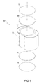
- FIG. 5 an exploded view of an alternative embodiment of an outer shell 62 for use in a magnet assembly is shown.
- the outer shell 62 is constructed using a composite cylinder 64, which is joined together via two flanges, an upper composite flange 66, and a lower composite flange 68.
- the composite cylinder 64 and the composite flanges 66 and 68 may be made of a fiber or plastic material, such as fiberglass, ceramic, or plastic. These components 64, 66, and 68 may be thermally fused or joined to form a closed pancake-shaped structure.
- a thin metallic outer lining 70 having an inner diameter substantially equal to the outer diameter of the composite cylinder 64 is then welded with two metallic discs, an upper metallic lining 72 and a lower metallic lining 74.
- the outer shell 62 thus formed includes a vacuum volume or a vacuum cavity, within which is disposed a superconducting magnet assembly.
- Such a magnet assembly may be utilized for an open MR system, such as an open MRI or open magnetic resonance
- FIG. 6 is a diagrammatic view of a superconducting magnet that may be disposed horizontally within an outer shell of a magnet assembly in an MR system.
- the composite bobbin 42 of the superconducting magnet assembly 26 includes recesses 44. Although only two recesses 44 are shown, the composite bobbin 42 may include more recesses.
- the recesses 44 are wound with a superconducting coil 46.
- the superconducting coil 46 in the two recesses 44 are joined together via jumpers or electrical coupling that runs over the composite bobbin 42. Leads 54 of the superconducting coil 46 are conducted to electrical coupling with a magnet operation control circuitry.
- a cryogen coil 76 is arranged over the composite bobbin 42 in an anti-vapor-locking configuration, as shown.
- the cryogen coil 76 may be disposed in a commonly known refrigerator cooling coil configuration.
- This refrigerator cooling coil configuration in the horizontally-oriented superconducting magnet structure 26 prevents vapor-locking of the cryogen, as will be appreciated by those skilled in the art.
- the cryogen feed mechanism feeds liquid helium, or other cryogen known in the art, into the cryogen coil 76 in a direction shown generally by reference numeral 78.
- the cryogen flows down into the bottom 80 of the cryogen coil 76.
- the cryogen vaporizes and passes through the serpentine cryogen coil 76, without any cryogen vapor being locked in the cryogen coil 76.
- the vaporized cryogen escapes into the cryogen feed mechanism in the direction generally shown by reference numeral 82.
- the composite bobbin 42 made of thermally conductive material, as described previously helps in conducting heat away from the superconducting coils thus maintaining superconducting operation. The generated heat is conducted away towards the cryogenic coil 48. The thermally conductive composite bobbin 42 therefore reduces the thermal gradient between the superconducting coil 46 and the cryogenic coil 48.
- FIG. 7 is a diagrammatic view of a superconducting magnet that may be disposed vertically within an outer shell of a magnet assembly in an MR system.
- FIG. 7 shows the composite bobbin 42 of the superconducting magnet assembly 26 including the recesses 44.
- cryogen coil 84 is arranged over the composite bobbin 42 in an anti-vapor-locking configuration.
- the cryogen coil 84 is disposed in a helical configuration. Again, this helical configuration in the vertically-oriented superconducting magnet structure 26 prevents vapor-locking of the cryogen.
- the cryogen feed mechanism feeds cryogen into the cryogen coil 84 in a direction shown generally by reference numeral 86.
- the cryogen cools the superconducting magnet 26 and vaporizes through the spiral cryogen coil 84.
- the vaporized cryogen escapes into the cryogen feed mechanism in the direction generally shown by reference numeral 88.
- a magnetic resonance (MR) system 90 such as for a magnetic resonance imaging or magnetic resonance spectroscopy application, is shown in which the forgoing structures are incorporated.
- the MR system 90 shows a closed MR system, having a bore 92 for receiving a subject 94.
- Subject 94 may lie over a patient table 96 that may be introduced into the bore 92.
- a magnet assembly 10 including a superconducting magnet assembly 26 made via the techniques discussed above may be utilized to generate the magnetic field for the MR system 90.
- the superconducting operation may be controlled via an imaging control circuitry 98.
- the magnetic field for the open MR system 100 may be generated by a magnet assembly 10.
- the magnet assembly 10 may include an outer shell 62, constructed in accordance with the teachings of FIG. 5.
- a superconducting magnet assembly 26 may be disposed, which may have a thick disc shape without a bore. Again, the superconducting operation may be controlled via an imaging control circuitry 98.
- the magnet assembly 10 including the outer shell 12 that encloses the superconducting magnet assembly 26, may be constructed in a conventional patient bore configuration, an open MRI configuration, a long-U configuration, among others.
Landscapes
- Physics & Mathematics (AREA)
- Engineering & Computer Science (AREA)
- Power Engineering (AREA)
- Electromagnetism (AREA)
- Condensed Matter Physics & Semiconductors (AREA)
- General Physics & Mathematics (AREA)
- Magnetic Resonance Imaging Apparatus (AREA)
- Containers, Films, And Cooling For Superconductive Devices (AREA)
Applications Claiming Priority (1)
| Application Number | Priority Date | Filing Date | Title |
|---|---|---|---|
| US11/182,622 US7053740B1 (en) | 2005-07-15 | 2005-07-15 | Low field loss cold mass structure for superconducting magnets |
Publications (1)
| Publication Number | Publication Date |
|---|---|
| EP1744170A1 true EP1744170A1 (de) | 2007-01-17 |
Family
ID=36462640
Family Applications (1)
| Application Number | Title | Priority Date | Filing Date |
|---|---|---|---|
| EP06253559A Ceased EP1744170A1 (de) | 2005-07-15 | 2006-07-06 | Kaltmassestruktur mit geringem Feldverlust für supraleitende Magneten |
Country Status (3)
| Country | Link |
|---|---|
| US (1) | US7053740B1 (de) |
| EP (1) | EP1744170A1 (de) |
| JP (1) | JP2007027715A (de) |
Cited By (5)
| Publication number | Priority date | Publication date | Assignee | Title |
|---|---|---|---|---|
| GB2432725A (en) * | 2005-11-28 | 2007-05-30 | Gen Electric | A cooling system with a discrete thermally conductive path between a superconductive coil and a cryogenic circuit |
| US7626477B2 (en) | 2005-11-28 | 2009-12-01 | General Electric Company | Cold mass cryogenic cooling circuit inlet path avoidance of direct conductive thermal engagement with substantially conductive coupler for superconducting magnet |
| US8188742B2 (en) | 2009-07-31 | 2012-05-29 | General Electric Company | System and method for thermo-electric cooling of RF coils in an MR imaging system |
| CN107991635A (zh) * | 2017-11-24 | 2018-05-04 | 上海联影医疗科技有限公司 | 一种用于磁共振系统的冷却组件及磁共振系统 |
| US11187381B2 (en) | 2017-09-29 | 2021-11-30 | Shanghai United Imaging Healthcare Co., Ltd. | Cryostat devices for magnetic resonance imaging and methods for making |
Families Citing this family (21)
| Publication number | Priority date | Publication date | Assignee | Title |
|---|---|---|---|---|
| DE102004043987B3 (de) * | 2004-09-11 | 2006-05-11 | Bruker Biospin Gmbh | Supraleitfähige Magnetspulenanordnung |
| US7421162B2 (en) * | 2005-03-22 | 2008-09-02 | General Electric Company | Fiber optic sensing device and method of making and operating the same |
| US7705701B2 (en) * | 2005-07-15 | 2010-04-27 | General Electric Company | Thin metal layer vacuum vessels with composite structural support |
| GB2437114B (en) * | 2006-04-13 | 2008-12-17 | Siemens Magnet Technology Ltd | Method Of Manufacturing A Solenoidal Magnet |
| US7718897B2 (en) * | 2006-05-19 | 2010-05-18 | General Electric Company | Low AC loss superconductor for a superconducting magnet and method of making same |
| US7838774B2 (en) * | 2006-05-19 | 2010-11-23 | General Electric Company | Low AC loss single-filament superconductor for a superconducting magnet and method of making same |
| US7518370B2 (en) * | 2006-11-30 | 2009-04-14 | General Electric Company | Low eddy current vacuum vessel and method of making same |
| US20080209919A1 (en) * | 2007-03-01 | 2008-09-04 | Philips Medical Systems Mr, Inc. | System including a heat exchanger with different cryogenic fluids therein and method of using the same |
| US7449889B1 (en) * | 2007-06-25 | 2008-11-11 | General Electric Company | Heat pipe cooled superconducting magnets with ceramic coil forms |
| US7498814B1 (en) * | 2007-10-31 | 2009-03-03 | General Electric Company | Magnet assembly for magnetic resonance imaging system |
| GB2456159A (en) * | 2008-01-04 | 2009-07-08 | Siemens Magnet Technology Ltd | Magnetic Coil Former |
| CN102148083B (zh) * | 2010-02-09 | 2013-04-03 | 通用电气公司 | 超导磁体 |
| CN102403081B (zh) | 2010-09-17 | 2015-02-11 | 通用电气公司 | 磁体组件及其制造方法 |
| US8374663B2 (en) * | 2011-01-31 | 2013-02-12 | General Electric Company | Cooling system and method for cooling superconducting magnet devices |
| GB2490478B (en) * | 2011-04-20 | 2014-04-23 | Siemens Plc | Superconducting magnets with thermal radiation shields |
| KR101486778B1 (ko) | 2013-07-03 | 2015-01-28 | 삼성전자주식회사 | 간접 냉각 방식의 초전도 자석 장치 |
| JP6139784B2 (ja) | 2013-07-26 | 2017-05-31 | コーニンクレッカ フィリップス エヌ ヴェKoninklijke Philips N.V. | 磁場に応答して超電導磁石システムのための冷却ループを制御する方法及び装置 |
| EP2849188B1 (de) | 2013-09-17 | 2019-04-03 | Samsung Electronics Co., Ltd | Kältemittelrekondensierungssystem und supraleitende Magnetvorrichtung damit |
| GB2532314B (en) * | 2014-10-27 | 2018-05-02 | Siemens Healthcare Ltd | Support of superconducting coils for MRI systems |
| US20180151280A1 (en) * | 2016-11-25 | 2018-05-31 | Shahin Pourrahimi | Pre-cooling and increasing thermal heat capacity of cryogen-free magnets |
| KR102705150B1 (ko) | 2019-07-09 | 2024-09-09 | 제네럴 일렉트릭 컴퍼니 | 자성 재료로 형성된 진공 용기를 포함하는 초전도 발전기 |
Citations (6)
| Publication number | Priority date | Publication date | Assignee | Title |
|---|---|---|---|---|
| EP0151719A2 (de) * | 1983-12-06 | 1985-08-21 | BBC Aktiengesellschaft Brown, Boveri & Cie. | Magnetsystem für einen Kernspintomograph |
| JPS6213010A (ja) * | 1985-07-11 | 1987-01-21 | Toshiba Corp | 超電導電磁石 |
| US4726199A (en) * | 1984-09-17 | 1988-02-23 | Kabushiki Kaisha Toshiba | Superconducting apparatus |
| WO2003098645A1 (de) * | 2002-05-15 | 2003-11-27 | Siemens Aktiengesellschaft | Einrichtung der supraleitungstechnik mit einem supraleitenden magneten und einer kälteeinheit |
| US20040119472A1 (en) * | 2002-12-23 | 2004-06-24 | General Electric Company | Conduction cooled passively-shielded mri magnet |
| EP1533625A1 (de) * | 2003-11-19 | 2005-05-25 | General Electric Company | Kühlmittel-Kreislauf mit wenig Wirbelströmen für supraleitende Magneten |
Family Cites Families (8)
| Publication number | Priority date | Publication date | Assignee | Title |
|---|---|---|---|---|
| JPS57177509A (en) * | 1981-04-24 | 1982-11-01 | Mitsubishi Electric Corp | Superconducting coil device |
| JPH0727814B2 (ja) * | 1985-02-05 | 1995-03-29 | 株式会社日立製作所 | 強制冷却超電導コイル装置 |
| JPH01259511A (ja) * | 1988-04-08 | 1989-10-17 | Mitsubishi Electric Corp | 超電導コイル |
| JPH0738339B2 (ja) * | 1991-10-18 | 1995-04-26 | 株式会社東芝 | 超電導装置 |
| US5410286A (en) * | 1994-02-25 | 1995-04-25 | General Electric Company | Quench-protected, refrigerated superconducting magnet |
| JPH11233334A (ja) * | 1998-02-18 | 1999-08-27 | Hitachi Ltd | 伝導冷却式超電導磁石装置 |
| JP2001307915A (ja) * | 2000-04-20 | 2001-11-02 | Toyobo Co Ltd | 伝導冷却式超電導マグネット用複合材料強化繊維 |
| JP2003179277A (ja) * | 2001-12-11 | 2003-06-27 | Hitachi Ltd | 超電導量子干渉デバイス格納用極低温容器 |
-
2005
- 2005-07-15 US US11/182,622 patent/US7053740B1/en not_active Expired - Lifetime
-
2006
- 2006-07-06 EP EP06253559A patent/EP1744170A1/de not_active Ceased
- 2006-07-07 JP JP2006187423A patent/JP2007027715A/ja active Pending
Patent Citations (6)
| Publication number | Priority date | Publication date | Assignee | Title |
|---|---|---|---|---|
| EP0151719A2 (de) * | 1983-12-06 | 1985-08-21 | BBC Aktiengesellschaft Brown, Boveri & Cie. | Magnetsystem für einen Kernspintomograph |
| US4726199A (en) * | 1984-09-17 | 1988-02-23 | Kabushiki Kaisha Toshiba | Superconducting apparatus |
| JPS6213010A (ja) * | 1985-07-11 | 1987-01-21 | Toshiba Corp | 超電導電磁石 |
| WO2003098645A1 (de) * | 2002-05-15 | 2003-11-27 | Siemens Aktiengesellschaft | Einrichtung der supraleitungstechnik mit einem supraleitenden magneten und einer kälteeinheit |
| US20040119472A1 (en) * | 2002-12-23 | 2004-06-24 | General Electric Company | Conduction cooled passively-shielded mri magnet |
| EP1533625A1 (de) * | 2003-11-19 | 2005-05-25 | General Electric Company | Kühlmittel-Kreislauf mit wenig Wirbelströmen für supraleitende Magneten |
Non-Patent Citations (2)
| Title |
|---|
| GREEN M A: "HELIUM COOLING SYSTEMS FOR LARGE SUPERCONDUCTING PHYSICS DETECTOR MAGNETS", CRYOGENICS, ELSEVIER, KIDLINGTON, GB, vol. 32, January 1992 (1992-01-01), pages 126 - 129, XP000321177, ISSN: 0011-2275 * |
| PATENT ABSTRACTS OF JAPAN vol. 011, no. 182 (E - 515) 11 June 1987 (1987-06-11) * |
Cited By (8)
| Publication number | Priority date | Publication date | Assignee | Title |
|---|---|---|---|---|
| GB2432725A (en) * | 2005-11-28 | 2007-05-30 | Gen Electric | A cooling system with a discrete thermally conductive path between a superconductive coil and a cryogenic circuit |
| US7319329B2 (en) | 2005-11-28 | 2008-01-15 | General Electric Company | Cold mass with discrete path substantially conductive coupler for superconducting magnet and cryogenic cooling circuit |
| GB2432725B (en) * | 2005-11-28 | 2009-10-21 | Gen Electric | Cold mass with discrete path substantially conductive coupler for superconducting magnet and cryogenic cooling circuit |
| US7626477B2 (en) | 2005-11-28 | 2009-12-01 | General Electric Company | Cold mass cryogenic cooling circuit inlet path avoidance of direct conductive thermal engagement with substantially conductive coupler for superconducting magnet |
| US8188742B2 (en) | 2009-07-31 | 2012-05-29 | General Electric Company | System and method for thermo-electric cooling of RF coils in an MR imaging system |
| US11187381B2 (en) | 2017-09-29 | 2021-11-30 | Shanghai United Imaging Healthcare Co., Ltd. | Cryostat devices for magnetic resonance imaging and methods for making |
| US12129971B2 (en) | 2017-09-29 | 2024-10-29 | Shanghai United Imaging Healthcare Co., Ltd. | Cryostat devices for magnetic resonance imaging and methods for making |
| CN107991635A (zh) * | 2017-11-24 | 2018-05-04 | 上海联影医疗科技有限公司 | 一种用于磁共振系统的冷却组件及磁共振系统 |
Also Published As
| Publication number | Publication date |
|---|---|
| US7053740B1 (en) | 2006-05-30 |
| JP2007027715A (ja) | 2007-02-01 |
Similar Documents
| Publication | Publication Date | Title |
|---|---|---|
| US7053740B1 (en) | Low field loss cold mass structure for superconducting magnets | |
| US7705701B2 (en) | Thin metal layer vacuum vessels with composite structural support | |
| US6783059B2 (en) | Conduction cooled passively-shielded MRI magnet | |
| US8033121B2 (en) | Low eddy current cryogen circuit for superconducting magnets | |
| EP2075805B1 (de) | Spule mit supraleitenden Windungen mit Kühlung ohne kryogenische Flüssigkeiten | |
| EP0773565B1 (de) | Offener kryogengekühlter supraleitender Magnet für die Bilderzeugung durch magnetische Resonanz | |
| US5677630A (en) | Planar superconducting MRI magnet | |
| US4935714A (en) | Low thermal conductance support for a radiation shield in a MR magnet | |
| US4902995A (en) | Cable suspension system for cylindrical cryogenic vessels | |
| US5442928A (en) | Hybrid cooling system for a superconducting magnet | |
| EP0350267A1 (de) | Supraleitender Magnetresonanz-Magnet | |
| US7498814B1 (en) | Magnet assembly for magnetic resonance imaging system | |
| CN106098290B (zh) | 超导磁体 | |
| JPH0335815B2 (de) | ||
| US5179338A (en) | Refrigerated superconducting MR magnet with integrated gradient coils | |
| US5381122A (en) | Open MRI magnet having a support structure | |
| JPH04225503A (ja) | 冷凍剤不要の能動遮蔽型磁気共鳴磁石 | |
| JPH01501211A (ja) | シールドされた磁気共鳴磁石を製造する方法 | |
| US6323749B1 (en) | MRI with superconducting coil | |
| JPH09120912A (ja) | 開構造伝導冷却型磁気共鳴作像マグネット | |
| US5225782A (en) | Eddy current free MRI magnet with integrated gradient coils | |
| EP0460601B1 (de) | Supraleitende Magnetanordnung mit Kühlmittelkreislauf | |
| CN117406151A (zh) | 用于磁共振成像装置的热总线结构件 | |
| CN119852051A (zh) | 用于将用于磁共振成像系统的超导磁体的氦浴槽冷却系统转换为密封深冷系统的系统和方法 |
Legal Events
| Date | Code | Title | Description |
|---|---|---|---|
| PUAI | Public reference made under article 153(3) epc to a published international application that has entered the european phase |
Free format text: ORIGINAL CODE: 0009012 |
|
| AK | Designated contracting states |
Kind code of ref document: A1 Designated state(s): AT BE BG CH CY CZ DE DK EE ES FI FR GB GR HU IE IS IT LI LT LU LV MC NL PL PT RO SE SI SK TR |
|
| AX | Request for extension of the european patent |
Extension state: AL BA HR MK YU |
|
| 17P | Request for examination filed |
Effective date: 20070717 |
|
| 17Q | First examination report despatched |
Effective date: 20070817 |
|
| AKX | Designation fees paid |
Designated state(s): DE GB NL |
|
| APBN | Date of receipt of notice of appeal recorded |
Free format text: ORIGINAL CODE: EPIDOSNNOA2E |
|
| APAF | Appeal reference modified |
Free format text: ORIGINAL CODE: EPIDOSCREFNE |
|
| APBT | Appeal procedure closed |
Free format text: ORIGINAL CODE: EPIDOSNNOA9E |
|
| STAA | Information on the status of an ep patent application or granted ep patent |
Free format text: STATUS: THE APPLICATION HAS BEEN REFUSED |
|
| 18R | Application refused |
Effective date: 20090525 |