EP1744401A1 - Boîtier de connexion - Google Patents
Boîtier de connexion Download PDFInfo
- Publication number
- EP1744401A1 EP1744401A1 EP05022336A EP05022336A EP1744401A1 EP 1744401 A1 EP1744401 A1 EP 1744401A1 EP 05022336 A EP05022336 A EP 05022336A EP 05022336 A EP05022336 A EP 05022336A EP 1744401 A1 EP1744401 A1 EP 1744401A1
- Authority
- EP
- European Patent Office
- Prior art keywords
- cables
- connector
- box
- notches
- connectors
- Prior art date
- Legal status (The legal status is an assumption and is not a legal conclusion. Google has not performed a legal analysis and makes no representation as to the accuracy of the status listed.)
- Withdrawn
Links
- 238000009434 installation Methods 0.000 claims description 3
- 238000004519 manufacturing process Methods 0.000 description 5
- 239000004020 conductor Substances 0.000 description 4
- 230000037431 insertion Effects 0.000 description 4
- 238000003780 insertion Methods 0.000 description 4
- 230000000295 complement effect Effects 0.000 description 2
- 230000008878 coupling Effects 0.000 description 2
- 238000010168 coupling process Methods 0.000 description 2
- 238000005859 coupling reaction Methods 0.000 description 2
- 239000002184 metal Substances 0.000 description 2
- 238000009413 insulation Methods 0.000 description 1
- 239000000463 material Substances 0.000 description 1
Images
Classifications
-
- H—ELECTRICITY
- H01—ELECTRIC ELEMENTS
- H01R—ELECTRICALLY-CONDUCTIVE CONNECTIONS; STRUCTURAL ASSOCIATIONS OF A PLURALITY OF MUTUALLY-INSULATED ELECTRICAL CONNECTING ELEMENTS; COUPLING DEVICES; CURRENT COLLECTORS
- H01R4/00—Electrically-conductive connections between two or more conductive members in direct contact, i.e. touching one another; Means for effecting or maintaining such contact; Electrically-conductive connections having two or more spaced connecting locations for conductors and using contact members penetrating insulation
- H01R4/24—Connections using contact members penetrating or cutting insulation or cable strands
- H01R4/2416—Connections using contact members penetrating or cutting insulation or cable strands the contact members having insulation-cutting edges, e.g. of tuning fork type
- H01R4/2445—Connections using contact members penetrating or cutting insulation or cable strands the contact members having insulation-cutting edges, e.g. of tuning fork type the contact members having additional means acting on the insulation or the wire, e.g. additional insulation penetrating means, strain relief means or wire cutting knives
- H01R4/245—Connections using contact members penetrating or cutting insulation or cable strands the contact members having insulation-cutting edges, e.g. of tuning fork type the contact members having additional means acting on the insulation or the wire, e.g. additional insulation penetrating means, strain relief means or wire cutting knives the additional means having two or more slotted flat portions
-
- H—ELECTRICITY
- H01—ELECTRIC ELEMENTS
- H01R—ELECTRICALLY-CONDUCTIVE CONNECTIONS; STRUCTURAL ASSOCIATIONS OF A PLURALITY OF MUTUALLY-INSULATED ELECTRICAL CONNECTING ELEMENTS; COUPLING DEVICES; CURRENT COLLECTORS
- H01R4/00—Electrically-conductive connections between two or more conductive members in direct contact, i.e. touching one another; Means for effecting or maintaining such contact; Electrically-conductive connections having two or more spaced connecting locations for conductors and using contact members penetrating insulation
- H01R4/24—Connections using contact members penetrating or cutting insulation or cable strands
- H01R4/2416—Connections using contact members penetrating or cutting insulation or cable strands the contact members having insulation-cutting edges, e.g. of tuning fork type
- H01R4/242—Connections using contact members penetrating or cutting insulation or cable strands the contact members having insulation-cutting edges, e.g. of tuning fork type the contact members being plates having a single slot
- H01R4/2425—Flat plates, e.g. multi-layered flat plates
- H01R4/2429—Flat plates, e.g. multi-layered flat plates mounted in an insulating base
- H01R4/2433—Flat plates, e.g. multi-layered flat plates mounted in an insulating base one part of the base being movable to push the cable into the slot
-
- H—ELECTRICITY
- H01—ELECTRIC ELEMENTS
- H01R—ELECTRICALLY-CONDUCTIVE CONNECTIONS; STRUCTURAL ASSOCIATIONS OF A PLURALITY OF MUTUALLY-INSULATED ELECTRICAL CONNECTING ELEMENTS; COUPLING DEVICES; CURRENT COLLECTORS
- H01R12/00—Structural associations of a plurality of mutually-insulated electrical connecting elements, specially adapted for printed circuits, e.g. printed circuit boards [PCB], flat or ribbon cables, or like generally planar structures, e.g. terminal strips, terminal blocks; Coupling devices specially adapted for printed circuits, flat or ribbon cables, or like generally planar structures; Terminals specially adapted for contact with, or insertion into, printed circuits, flat or ribbon cables, or like generally planar structures
- H01R12/50—Fixed connections
- H01R12/59—Fixed connections for flexible printed circuits, flat or ribbon cables or like structures
- H01R12/61—Fixed connections for flexible printed circuits, flat or ribbon cables or like structures connecting to flexible printed circuits, flat or ribbon cables or like structures
- H01R12/613—Fixed connections for flexible printed circuits, flat or ribbon cables or like structures connecting to flexible printed circuits, flat or ribbon cables or like structures by means of interconnecting elements
- H01R12/616—Fixed connections for flexible printed circuits, flat or ribbon cables or like structures connecting to flexible printed circuits, flat or ribbon cables or like structures by means of interconnecting elements having contacts penetrating insulation for making contact with conductors, e.g. needle points
-
- H—ELECTRICITY
- H01—ELECTRIC ELEMENTS
- H01R—ELECTRICALLY-CONDUCTIVE CONNECTIONS; STRUCTURAL ASSOCIATIONS OF A PLURALITY OF MUTUALLY-INSULATED ELECTRICAL CONNECTING ELEMENTS; COUPLING DEVICES; CURRENT COLLECTORS
- H01R4/00—Electrically-conductive connections between two or more conductive members in direct contact, i.e. touching one another; Means for effecting or maintaining such contact; Electrically-conductive connections having two or more spaced connecting locations for conductors and using contact members penetrating insulation
- H01R4/24—Connections using contact members penetrating or cutting insulation or cable strands
- H01R4/2416—Connections using contact members penetrating or cutting insulation or cable strands the contact members having insulation-cutting edges, e.g. of tuning fork type
- H01R4/2445—Connections using contact members penetrating or cutting insulation or cable strands the contact members having insulation-cutting edges, e.g. of tuning fork type the contact members having additional means acting on the insulation or the wire, e.g. additional insulation penetrating means, strain relief means or wire cutting knives
- H01R4/245—Connections using contact members penetrating or cutting insulation or cable strands the contact members having insulation-cutting edges, e.g. of tuning fork type the contact members having additional means acting on the insulation or the wire, e.g. additional insulation penetrating means, strain relief means or wire cutting knives the additional means having two or more slotted flat portions
- H01R4/2454—Connections using contact members penetrating or cutting insulation or cable strands the contact members having insulation-cutting edges, e.g. of tuning fork type the contact members having additional means acting on the insulation or the wire, e.g. additional insulation penetrating means, strain relief means or wire cutting knives the additional means having two or more slotted flat portions forming a U-shape with slotted branches
Definitions
- This invention refers to a terminal box, of those used in various installations, to route and bypass cables provided with a core and insulation sheathing.
- a typical case is the box used in the bypass of a multiple cable bundle, which consists of a box with an access cover. Splicing and bypassing is carried out inside the box, either manually or using more or less sophisticated splicing devices.
- the cables to be bypassed must be cut in order to splice them to the same line or to the corresponding bypasses, using terminal strips with bolted mechanical splices or similar.
- connection box of this invention has special technical features that enable electrical cables to be bypassed in a quick, simple and safe manner, without using coupling screws or clamps on the cable or cables to be connected and without the need to strip the cables to be connected.
- connection box of the invention consists of a base or box containing one or more sockets with slots to house separate electrical connectors.
- Each connector consists of an electrically conductive metal plate with at least one notch with cutting edges to tightly insert the cable or cables sideways.
- This notch has a smaller width than the external diameter of the cable and equal or slightly smaller than the diameter of the conductive core, so that when the cable is inserted in the aforementioned notch, the sheathing of the cables to be connected is cut and the core becomes in close contact.
- the connector is made of electrically conductive material, the conductive cores of all cables inserted in the same connector are directly interconnected.
- the cover of the box has projecting parts, which press the connected cables sideways, preventing them from coming out of the corresponding notches.
- the connectors are flat and the notches of each connector are at two levels, in order to place the main cables in one of them and the bypass cables in the other. This means that the insertion position of the main cables and of the bypass cables can be distinguished reducing the risk of error in insertion.
- the connectors can optionally consist of flat parts, folded in a "U”, with the connection notches aligned and shaped in the respective sides of the "U” configuration.
- connection box may have connectors with notches of different widths so that cables with different diameters can be electrically connected in the same box.
- the cover and the base may be joined using complementary press-on elements, threaded tightening elements or any other conventional fastening element, as this does not affect the essence of the invention.
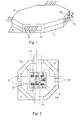
- the box consists of a lower base (1) and a cover (2), which in the assembly position form openings (11), which are longitudinally facing each other for the inlet and outlet of conductor cables (3), and side openings (12) for the outlet of bypass conductor cables (3).
- a socket (13) with slots (14) to insert the electrical connectors (4) is at the bottom of the box (1).
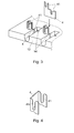
- each electrical connector (4) consists of a flat, electrically conductive metal part, with two notches (41) with cutting edges to insert the cables (3) to be connected.
- the notches in the connector are placed at two different heights, with the upper notch (41) aligned with a castellated shape projecting part to route the main cable (3), and the lower notch (41) aligned with a housing to place the bypass cable (3).
- the width of the notches (41) is smaller than the outer diameter of the cables (3) to be connected, so that when the cables (3) are inserted inside, the cutting edges cut the sheathing of the cables (3), make contact with the core, and therefore the connector (4) ensures the electrical interconnection of the main and bypass cables (3), inserted in the notches (41).
- connectors enable a cable (3) to be bypassed without the need to cut its core nor to strip or remove part of the sheathing, as the sheathing is cut by the cutting edges of the connector when the cable is inserted sideways in the notch of the connector.
- the notch (41) is sufficiently deep to house at least one cable (3), although it has also been planned that two or more cables (3) can be inserted in the same notch (41) of the connector (4), so that they are electrically connected by contact of the corresponding cores with the connector (4).
- the connectors (4) consist of flat parts, folded in a "U”, with cutting-edged notches (41) on the sides, so that the cables (3) to be connected can be inserted sideways.
Landscapes
- Multi-Conductor Connections (AREA)
- Connections By Means Of Piercing Elements, Nuts, Or Screws (AREA)
Applications Claiming Priority (1)
| Application Number | Priority Date | Filing Date | Title |
|---|---|---|---|
| ES200501692A ES2296458B1 (es) | 2005-07-12 | 2005-07-12 | Caja de conexiones. |
Publications (1)
| Publication Number | Publication Date |
|---|---|
| EP1744401A1 true EP1744401A1 (fr) | 2007-01-17 |
Family
ID=37025001
Family Applications (1)
| Application Number | Title | Priority Date | Filing Date |
|---|---|---|---|
| EP05022336A Withdrawn EP1744401A1 (fr) | 2005-07-12 | 2005-10-13 | Boîtier de connexion |
Country Status (2)
| Country | Link |
|---|---|
| EP (1) | EP1744401A1 (fr) |
| ES (1) | ES2296458B1 (fr) |
Citations (5)
| Publication number | Priority date | Publication date | Assignee | Title |
|---|---|---|---|---|
| US4778405A (en) * | 1984-10-05 | 1988-10-18 | Amp Incorporated | T-tap electrical connector having opening for test probe |
| US5199899A (en) * | 1990-09-19 | 1993-04-06 | Societe Labinal | Branch connector for electrically connecting two electrical conductors |
| US5820404A (en) * | 1995-07-10 | 1998-10-13 | Sumitomo Wiring Systems, Ltd. | Terminal and cramping connector |
| US6443755B1 (en) * | 1998-07-02 | 2002-09-03 | Expert Explosives (Proprietary) Limited | Trunk line connector |
| DE10159754A1 (de) * | 2000-12-11 | 2002-09-12 | Sumitomo Wiring Systems | Verbinder und Verfahren zum Verbinden eines Drahtes |
Family Cites Families (3)
| Publication number | Priority date | Publication date | Assignee | Title |
|---|---|---|---|---|
| US4525019A (en) * | 1982-02-23 | 1985-06-25 | Brasky Joseph L | Self-stripping connector for insulated wires |
| FR2665803B1 (fr) * | 1990-08-09 | 1993-06-18 | Labinal | Connecteur de derivation. |
| JP3881857B2 (ja) * | 2001-08-30 | 2007-02-14 | 矢崎総業株式会社 | ジョイントコネクタ |
-
2005
- 2005-07-12 ES ES200501692A patent/ES2296458B1/es not_active Expired - Fee Related
- 2005-10-13 EP EP05022336A patent/EP1744401A1/fr not_active Withdrawn
Patent Citations (5)
| Publication number | Priority date | Publication date | Assignee | Title |
|---|---|---|---|---|
| US4778405A (en) * | 1984-10-05 | 1988-10-18 | Amp Incorporated | T-tap electrical connector having opening for test probe |
| US5199899A (en) * | 1990-09-19 | 1993-04-06 | Societe Labinal | Branch connector for electrically connecting two electrical conductors |
| US5820404A (en) * | 1995-07-10 | 1998-10-13 | Sumitomo Wiring Systems, Ltd. | Terminal and cramping connector |
| US6443755B1 (en) * | 1998-07-02 | 2002-09-03 | Expert Explosives (Proprietary) Limited | Trunk line connector |
| DE10159754A1 (de) * | 2000-12-11 | 2002-09-12 | Sumitomo Wiring Systems | Verbinder und Verfahren zum Verbinden eines Drahtes |
Also Published As
| Publication number | Publication date |
|---|---|
| ES2296458B1 (es) | 2009-03-01 |
| ES2296458A1 (es) | 2008-04-16 |
Similar Documents
| Publication | Publication Date | Title |
|---|---|---|
| US6201187B1 (en) | Pre-wired universal junction block | |
| KR100238930B1 (ko) | 플러그를 끼울수 있는 모듈 스플라이싱 커넥터 및 브리징 어댑터 | |
| US11387591B2 (en) | Plug connector module for an industrial plug connector | |
| US6558190B1 (en) | Method and system of an installer-friendly, modularly adaptable, electrical, outlet gang box | |
| US4386820A (en) | Modular connector for power systems | |
| US6045374A (en) | Electrical wiring system | |
| US6777611B2 (en) | Switch/power drop unit for modular wiring system | |
| US5525754A (en) | Prewired junction box | |
| US5925850A (en) | Electrical outlet, switch and junction boxs | |
| CN104241938B (zh) | 用于混合光纤线缆的过渡连接器 | |
| US6544049B1 (en) | Electrical unit for mating with an electrical box | |
| US6333464B1 (en) | Electric wire splice connector | |
| US7804026B2 (en) | Enclosure for wiring devices | |
| US11670922B2 (en) | Power and/or data connectivity track system | |
| US5669778A (en) | IDC branch connector for large range of wire sizes | |
| US4212507A (en) | Selective interconnection system and connector | |
| EP1744401A1 (fr) | Boîtier de connexion | |
| AU2020289801A1 (en) | Patch panel arrangments, cable terminating devices & methods | |
| JP7843768B2 (ja) | 内部導電素子を有する電気ボックス | |
| US20140027143A1 (en) | Electrical Box Insert Device | |
| CH646820A5 (fr) | Boite a broches electriques et composant correspondant. | |
| US5212346A (en) | Electrical junction box | |
| US20260128546A1 (en) | Electrical connectors for splicing connections | |
| JP3485053B2 (ja) | 連鎖状接続端子、該接続用端子を用いたジョイントコネクタ及び該ジョイントコネクタを備えたワイヤハーネス | |
| EP2187493B2 (fr) | Boîte de jonction pour systèmes électriques et similaire. |
Legal Events
| Date | Code | Title | Description |
|---|---|---|---|
| PUAI | Public reference made under article 153(3) epc to a published international application that has entered the european phase |
Free format text: ORIGINAL CODE: 0009012 |
|
| AK | Designated contracting states |
Kind code of ref document: A1 Designated state(s): AT BE BG CH CY CZ DE DK EE ES FI FR GB GR HU IE IS IT LI LT LU LV MC NL PL PT RO SE SI SK TR |
|
| AX | Request for extension of the european patent |
Extension state: AL BA HR MK YU |
|
| AKX | Designation fees paid |
Designated state(s): AT BE BG CH CY CZ DE DK EE ES FI FR GB GR HU IE IS IT LI LT LU LV MC NL PL PT RO SE SI SK TR |
|
| AXX | Extension fees paid |
Extension state: YU Payment date: 20051013 Extension state: MK Payment date: 20051013 Extension state: HR Payment date: 20051013 Extension state: BA Payment date: 20051013 Extension state: AL Payment date: 20051013 |
|
| STAA | Information on the status of an ep patent application or granted ep patent |
Free format text: STATUS: THE APPLICATION IS DEEMED TO BE WITHDRAWN |
|
| 18D | Application deemed to be withdrawn |
Effective date: 20070718 |