EP1744594A2 - Corps de chauffe - Google Patents
Corps de chauffe Download PDFInfo
- Publication number
- EP1744594A2 EP1744594A2 EP06014709A EP06014709A EP1744594A2 EP 1744594 A2 EP1744594 A2 EP 1744594A2 EP 06014709 A EP06014709 A EP 06014709A EP 06014709 A EP06014709 A EP 06014709A EP 1744594 A2 EP1744594 A2 EP 1744594A2
- Authority
- EP
- European Patent Office
- Prior art keywords
- heating
- tube
- heating member
- supporting unit
- heating body
- Prior art date
- Legal status (The legal status is an assumption and is not a legal conclusion. Google has not performed a legal analysis and makes no representation as to the accuracy of the status listed.)
- Granted
Links
- 238000010438 heat treatment Methods 0.000 title claims abstract description 147
- 229910052751 metal Inorganic materials 0.000 claims description 16
- 239000002184 metal Substances 0.000 claims description 16
- 238000007789 sealing Methods 0.000 claims description 11
- 239000010453 quartz Substances 0.000 description 15
- VYPSYNLAJGMNEJ-UHFFFAOYSA-N silicon dioxide Inorganic materials O=[Si]=O VYPSYNLAJGMNEJ-UHFFFAOYSA-N 0.000 description 15
- 238000009413 insulation Methods 0.000 description 10
- WABPQHHGFIMREM-UHFFFAOYSA-N lead(0) Chemical compound [Pb] WABPQHHGFIMREM-UHFFFAOYSA-N 0.000 description 10
- OKTJSMMVPCPJKN-UHFFFAOYSA-N Carbon Chemical compound [C] OKTJSMMVPCPJKN-UHFFFAOYSA-N 0.000 description 8
- 229910052799 carbon Inorganic materials 0.000 description 8
- 239000011261 inert gas Substances 0.000 description 4
- 239000000463 material Substances 0.000 description 3
- PXHVJJICTQNCMI-UHFFFAOYSA-N Nickel Chemical compound [Ni] PXHVJJICTQNCMI-UHFFFAOYSA-N 0.000 description 2
- 239000003575 carbonaceous material Substances 0.000 description 2
- 239000007789 gas Substances 0.000 description 2
- 230000004048 modification Effects 0.000 description 2
- 238000012986 modification Methods 0.000 description 2
- VYZAMTAEIAYCRO-UHFFFAOYSA-N Chromium Chemical compound [Cr] VYZAMTAEIAYCRO-UHFFFAOYSA-N 0.000 description 1
- 239000000956 alloy Substances 0.000 description 1
- 229910045601 alloy Inorganic materials 0.000 description 1
- 229910052736 halogen Inorganic materials 0.000 description 1
- 150000002367 halogens Chemical class 0.000 description 1
- 229910052759 nickel Inorganic materials 0.000 description 1
- 230000000704 physical effect Effects 0.000 description 1
- 239000000126 substance Substances 0.000 description 1
- WFKWXMTUELFFGS-UHFFFAOYSA-N tungsten Chemical compound [W] WFKWXMTUELFFGS-UHFFFAOYSA-N 0.000 description 1
- 229910052721 tungsten Inorganic materials 0.000 description 1
- 239000010937 tungsten Substances 0.000 description 1
Images



Classifications
-
- H—ELECTRICITY
- H05—ELECTRIC TECHNIQUES NOT OTHERWISE PROVIDED FOR
- H05B—ELECTRIC HEATING; ELECTRIC LIGHT SOURCES NOT OTHERWISE PROVIDED FOR; CIRCUIT ARRANGEMENTS FOR ELECTRIC LIGHT SOURCES, IN GENERAL
- H05B3/00—Ohmic-resistance heating
- H05B3/02—Details
- H05B3/04—Waterproof or air-tight seals for heaters
-
- H—ELECTRICITY
- H05—ELECTRIC TECHNIQUES NOT OTHERWISE PROVIDED FOR
- H05B—ELECTRIC HEATING; ELECTRIC LIGHT SOURCES NOT OTHERWISE PROVIDED FOR; CIRCUIT ARRANGEMENTS FOR ELECTRIC LIGHT SOURCES, IN GENERAL
- H05B3/00—Ohmic-resistance heating
- H05B3/40—Heating elements having the shape of rods or tubes
- H05B3/42—Heating elements having the shape of rods or tubes non-flexible
- H05B3/44—Heating elements having the shape of rods or tubes non-flexible heating conductor arranged within rods or tubes of insulating material
Definitions
- the present invention relates to a heating body, and more particularly, to a heating body that can emit heat by converting predetermined energy into heat energy.
- a heating body is a device for converting electric energy into heat energy.
- a conventional heating body includes a filament that is a heating element, a quartz tube in which the filament is inserted, and a connection unit for connecting the filament to an external power source.
- the filament formed of a carbon material is inserted in the quartz tube and the quartz tube is sealed.
- the filament is connected to the external power source by the connection unit.
- the quartz tube is filled with inert gas such as vacuum gas or halogen gas so as to prevent the filament from be oxidized when the filament emits high temperature heat and thus increase the service life of the heating body.
- the carbon filament is formed in a spiral shape, a plate shape, a linear shape, or the like.
- the carbon filament may be connected an electrode by a clip or a spring providing a tension. Therefore, the filament is disposed in the quartz tube without contacting an inner surface of the quartz tube.
- the quartz tube is molten or broken at a temperature above 800°C. Therefore, when the carbon filament emitting heat contacts the inner surface of the quartz tube, the quartz tube may be damaged and thus the service life of the heating body is reduced. Therefore, the carbon filament is supported in the quartz tube by the clip or spring without directly contacting the inner surface of the quartz tube.
- the carbon filament in the conventional heat body, the carbon filament is tensioned by outer force not to contact the inner surface of the quartz tube.
- the carbon filament when the carbon filament emits high temperature heat, the carbon filament expands according to its thermal expansion coefficient. When the carbon filament expands, it may physically contact the inner surface of the quartz tube, thereby damaging the quartz tube and reducing the service life of the heating body.
- the present invention is directed to a heating body that substantially obviates one or more problems due to limitations and disadvantages of the related art.
- An object of the present invention is to provide a heating body that can prevent a heating member from contacting a tube enclosing the heating member.
- a heating body including: a tube; a heating member disposed in the tube; and a supporting unit disposed along a length of the tube to maintain a predetermined space between the tube and the heating member.
- a heating body including: a tube; a heating member disposed in the tube; and a supporting unit supporting the heating member along a length of the heating member to maintain a space between the tube and the heating member.
- a heating body including: a tube; a heating member disposed in the tube; a supporting unit disposed across the tube to maintain a space between the tube and the heating member; and a sealing member formed on an end of the tube to fix an end of the supporting unit.
- the heating member is supported by the heating unit, the contact of the heating member with the tube can be prevented even when the heating member droops due to the thermal expansion during the heat emission. As a result, the damage of the heating member and the tube can be prevented, thereby increasing the life cycle of the heating body.
- Fig. 1 is a perspective view of a heating body according to an embodiment of the present invention
- Fig. 2 is a sectional view taken along line I-I' of Fig. 1;
- Fig. 3 is an enlarged view of a portion A of Fig. 2;
- Fig. 4 is an enlarged view of a portion B of Fig. 2;
- Fig. 5 is a sectional view taken along line II-II' of Fig. 1;
- Fig. 6 is a perspective view of a heating body according to another embodiment of the present invention.
- Fig. 7 is a sectional view taken along line III-III' of Fig. 6.
- Fig. 1 is a perspective view of a heating body according to an embodiment of the present invention.
- a heating body 100 includes a tube 110 defining a space for receiving internal parts and a heating member 200 disposed in the tube to emit heat.
- the heating body 100 includes a lead rod 150 supporting the heating member 200 without allowing the heat member 200 to contact an inner surface of the tube 110 and a connection member 160 for connecting the lead rod 150 to the heating member 200.
- the heating body 100 further includes a metal member 140 connected to a portion of the lead rod 150 to allow an electric conduction between an external power source and the heating member 200 and an insulation member 130 for insulating the metal member 200 from an external side.
- the heating body 100 further includes a sealing member 120 partly enclosing and supporting the metal member 140, insulation member 130 and tube 110.
- the heating body 100 further includes a supporting unit 300, which prevents the heating member 200 from contacting the inner surface of the tube 110 when the heating member 200 emits heat and thus expands.
- the supporting unit 300 includes a first supporting member 310 and a second supporting member 320. The supporting unit 300 will be described later.
- the tube 110 functions to not only define the space for receiving the internal parts but also to protect the internal parts. Since the heating body 100 emits heat above hundreds °C, the tube 110 must be formed of a material having a sufficient rigidity and a sufficient heat-resistance. For example, the tube 110 may be formed of quartz. In addition, the tube 110 must be sealed to isolate the heating member 200 from the external side. Inert gas may be filled in the tube 110 to prevent the heating member 200 from changing in the chemical or physical property.
- the heat member 200 emits heat using electric energy applied.
- the heating member 200 may be formed of a material selected from the group consisting of a carbon-based material, a tungsten-based material, and a nickel/chrome-based alloy.
- connection member 160 includes a plurality of sections connected to opposite ends of the heating member 200. Therefore, the connection member 160 is connected to the lead rod 150 by the connection member 160. Then, the heating member 200 is tensioned not to maintain a state where it does not contact the inner surface of the tube 100. As a result, the heating member 200 can stably emit heat without contacting the tube 100.
- the lead rod 150 extends up to an external side of the tube 110. Therefore, the sealing state of the tube 110 is maintained and the heating member 200 can be connected to the external power source.
- the metal member 140 is connected to the end of the lead rod 150 extending out of the tube 110 to transmit electric energy from the external power source to the heating member 200 via the lead rod 150. Then, the heating member 20 receiving the electric energy emits the heat.
- the insulation member 130 insulates an exposed portion of the metal member 140 to an external side to prevent the electric leakage of the metal member 140.
- the insulation member 130 is designed to be fitted in a product where the heating body 100 will be installed.
- the sealing member 120 protects the end portion of the lead rod 150 and the connection portion of the metal member 140 from external impact.
- the sealing member 120 is assembled with the insulation member 130 and the tube 110 to maintain a predetermined shape of the heating body 100.
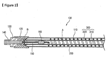
- Fig. 2 is a sectional view taken along line I-I' of Fig. 1.
- the heating body 100 includes the tube 110, the heating member 200 disposed in the tube 110, and the connection member 160, the lead rod 150 and metal member 140 that are consecutively connected to the heating member 200.
- the metal member 140 is insulated by the insulation member 130 and the insulation member 130 and the tube 110 are partly enclosed and supported by the sealing member 120.
- the heating member 200 is coiled by the predetermined number of turns.
- the supporting unit 300 is arranged extending in a longitudinal direction of the heating member 200.
- the supporting unit 300 is inserted in the heating member 200 such that it faces the heating member 200 in the longitudinal direction of the heating member 200.
- the supporting unit 300 supports the heating member 200 with respect to the overall length of the heating member 200.
- the heating member 200 droops due to its thermal expansion, it still maintains the supporting state by contacting the supporting unit 300.
- the heating member 200 emits the heat, the contact of the heating member 200 with the tube 110 can be prevented.
- the supporting unit 300 includes the first and second supporting members 310 and 320.
- the first and second supporting members 310 and 320 are symmetrically disposed with respect to the center of the heating member 200. Therefore, even when the heating member 200 thermal-expands, it can be supported by the first and/or second supporting member 310 and/or 320. Therefore, regardless of the drooping direction of the heating member 300, the heating member 300 can be reliably supported by the supporting members 310 and 320. As a result, when the heating member 300 emits the heat, the contact of the heating member 200 with the tube 110 can be more reliably prevented.
- the supporting unit 300 includes the two supporting members 310 and 320 in this embodiment, the present invention is not limited to this case. That is, the supporting unit 300 may two or more supporting members to more reliably supporting the heating member 200.
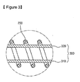
- Fig. 3 is an enlarged view of a portion A of Fig. 2.
- the supporting unit 300 and the heating member 200 are spaced apart from each through the overall length of the heating member 200. Therefore, the deformation of the supporting unit 300, which may be caused by an elastic force applied from the heating member 200 to the supporting unit, can be prevented by an elastic force that may be applied to the supporting unit 300, can be prevented. That is, when the supporting unit 300 is deformed by the elastic force, the supporting force of the supporting unit 300 for the heating member 200 may be reduced. However, by the above-described supporting structure, the reduction in the supporting force of the supporting unit 300 can be prevented. Even when the heating member 200 droops by the thermal expansion and thus contacts the supporting unit 300, the elastic force of the heating member 200 is reduced. Thus, the deformation of the supporting unit 300 is very small and the supporting reliability of the supporting unit 300 for the heating member 200 can be enhanced.
- Fig. 4 is an enlarged view of a portion B of Fig. 2.
- a distance d1 is defined between the supporting unit 300 and the metal member 140. Then, since the supporting unit 300 cannot contact the metal member 140 to maintain insulation between them. Therefore, the electric leakage to the heating member 200 by the metal member 140 can be prevented.
- An end of the supporting unit 300 passes through the tube 110 and is fixed on the sealing member 120, by which the supporting unit 300 has a predetermined supporting force to reliably support the heating member 200.
- the supporting unit 300 can also be fixed on an inner wall of the tube 110. In this case, the supporting force of the supporting unit 300 can be further enhanced to more reliably support the heating member 200.
- the supporting member 300 and the tube 110 are preferably sealed together. Then, the leakage of the inert gas filled in the tube 110 can be prevented. In order to more reliably prevent the leakage of the inert gas, it will be more preferable that the supporting member 300 and the sealing member 120 are sealed together.
- FIG. 5 is a sectional view taken along line II-II'.
- the heating member 200 is coiled by a predetermined number of turns and the supporting member 300 is inserted in the heat member 200.
- the supporting member 300 is spaced apart from the heating member 200 by a predetermined distance d2.
- a heating body according to another embodiment of the present invention will now be described. In this embodiment, the same parts as the foregoing embodiment will not be described.
- Fig. 6 is a perspective view of a heating body according to another embodiment of the present invention.
- a heating body 100 of this embodiment includes a tube 110 and a heating member 201 disposed in the tube 110.
- the heating member 201 is supportably connected to a lead rod 150 by a connection member 160.
- a side of the heating member 201 is connected to a metal member 140 for the electric connection with an external power source and enclosed by an insulation member 130.
- the metal member 140, the insulation member 130 and the tub 110 are partly enclosed and supported by a sealing member 120.
- the heating member 201 thermally expands during the heat emission. At this point, the contact of the heating member 201 with the tube 110 can be prevented by a supporting unit 300.
- the heating member 201 is formed in a weaved-shape.
- the supporting unit 300 is coupled to the heating member 201 along a length of the heating member 201 to support the heating member 201. This will be described in more detail later.
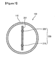
- Fig. 7 is a sectional view taken along line III-III' of Fig. 6.
- the heating member 201 is weaved in a plate shape.
- First and second supporting members 310 and 320 of the supporting unit 300 are coupled to the heating member 201. That is, the first and second supporting members 310 and 320 are spaced apart from each other and inserted in the heating member 201.
- the heating member 201 can be supported by the supporting unit 300. Therefore, the contact of the heating member 201 with the tube 110 can be prevented during the heat emission.
- the heating member is supported by the heating unit, the contact of the heating member with the tube can be prevented even when the heating member droops due to the thermal expansion during the heat emission. As a result, the damage of the heating member and the tube can be prevented, thereby increasing the life cycle of the heating body.
- the supporting unit includes two or more supporting members, the supporting force supporting the heating member can be enhanced, thereby more reliably supporting the heating member.
Landscapes
- Resistance Heating (AREA)
- Pipe Accessories (AREA)
- Surface Heating Bodies (AREA)
Applications Claiming Priority (1)
| Application Number | Priority Date | Filing Date | Title |
|---|---|---|---|
| KR1020050063729A KR100751111B1 (ko) | 2005-07-14 | 2005-07-14 | 발열체의 구조 |
Publications (3)
| Publication Number | Publication Date |
|---|---|
| EP1744594A2 true EP1744594A2 (fr) | 2007-01-17 |
| EP1744594A3 EP1744594A3 (fr) | 2008-08-20 |
| EP1744594B1 EP1744594B1 (fr) | 2012-05-23 |
Family
ID=37309457
Family Applications (1)
| Application Number | Title | Priority Date | Filing Date |
|---|---|---|---|
| EP06014709A Ceased EP1744594B1 (fr) | 2005-07-14 | 2006-07-14 | Corps de chauffe |
Country Status (5)
| Country | Link |
|---|---|
| US (1) | US7626147B2 (fr) |
| EP (1) | EP1744594B1 (fr) |
| JP (1) | JP5032066B2 (fr) |
| KR (1) | KR100751111B1 (fr) |
| CN (1) | CN1897770B (fr) |
Families Citing this family (8)
| Publication number | Priority date | Publication date | Assignee | Title |
|---|---|---|---|---|
| US20130315575A1 (en) * | 2012-05-23 | 2013-11-28 | Osram Sylvania Inc. | Concentric coil infrared emitter lamp |
| US10264629B2 (en) * | 2013-05-30 | 2019-04-16 | Osram Sylvania Inc. | Infrared heat lamp assembly |
| KR101480395B1 (ko) * | 2013-06-17 | 2015-01-09 | 원광대학교산학협력단 | 대기중에서 사용가능한 초고온 발열 장치 |
| KR102137032B1 (ko) | 2017-05-10 | 2020-07-23 | 엘지전자 주식회사 | 탄소 복합체 조성물 및 이를 이용하여 제조되는 탄소 히터 |
| US20180338350A1 (en) * | 2017-05-19 | 2018-11-22 | Lg Electronics Inc. | Carbon heater |
| KR102004035B1 (ko) * | 2017-05-26 | 2019-07-25 | 엘지전자 주식회사 | 탄소 발열체 |
| CN109618424A (zh) * | 2018-11-12 | 2019-04-12 | 东台中玻特种玻璃有限公司 | 退火窑电加热手 |
| KR102819223B1 (ko) * | 2020-11-23 | 2025-06-11 | 주식회사 원익아이피에스 | 히터 및 이를 포함하는 기판처리장치 |
Citations (1)
| Publication number | Priority date | Publication date | Assignee | Title |
|---|---|---|---|---|
| DE1615498A1 (de) | 1967-11-16 | 1970-07-30 | Vvb Tech Glas | Stabfoermiger,elektrischer Tauchheizkoerper |
Family Cites Families (8)
| Publication number | Priority date | Publication date | Assignee | Title |
|---|---|---|---|---|
| JPS4859242U (fr) * | 1971-11-06 | 1973-07-27 | ||
| US4041438A (en) * | 1976-02-17 | 1977-08-09 | Odette Landeroin Duvernois | Electric heating device |
| DE10029437B4 (de) * | 2000-06-21 | 2005-11-17 | Heraeus Noblelight Gmbh | Infrarotstrahler und Verfahren zum Betreiben eines solchen Infrarotstrahlers |
| JP3834475B2 (ja) * | 2000-12-25 | 2006-10-18 | ソーラム株式会社 | ヒータ |
| US6856078B2 (en) * | 2001-06-27 | 2005-02-15 | Asm America, Inc. | Lamp filament design |
| JP2003200261A (ja) * | 2001-12-28 | 2003-07-15 | Marcom:Kk | 加熱ユニットおよび静止型リフロー装置 |
| JP3836829B2 (ja) * | 2003-03-21 | 2006-10-25 | ジーエスシーオー インク. | カーボン糸から織成されたランプヒーター |
| CN2710302Y (zh) | 2004-07-05 | 2005-07-13 | 先锋电器集团有限公司 | 带芯棒的石英管发热件 |
-
2005
- 2005-07-14 KR KR1020050063729A patent/KR100751111B1/ko not_active Expired - Fee Related
-
2006
- 2006-07-13 US US11/457,296 patent/US7626147B2/en active Active
- 2006-07-14 JP JP2006194800A patent/JP5032066B2/ja not_active Expired - Fee Related
- 2006-07-14 EP EP06014709A patent/EP1744594B1/fr not_active Ceased
- 2006-07-14 CN CN2006101063605A patent/CN1897770B/zh not_active Expired - Fee Related
Patent Citations (1)
| Publication number | Priority date | Publication date | Assignee | Title |
|---|---|---|---|---|
| DE1615498A1 (de) | 1967-11-16 | 1970-07-30 | Vvb Tech Glas | Stabfoermiger,elektrischer Tauchheizkoerper |
Also Published As
| Publication number | Publication date |
|---|---|
| JP5032066B2 (ja) | 2012-09-26 |
| CN1897770A (zh) | 2007-01-17 |
| EP1744594B1 (fr) | 2012-05-23 |
| CN1897770B (zh) | 2010-09-15 |
| KR20070009824A (ko) | 2007-01-19 |
| JP2007027123A (ja) | 2007-02-01 |
| US20070034620A1 (en) | 2007-02-15 |
| KR100751111B1 (ko) | 2007-08-22 |
| EP1744594A3 (fr) | 2008-08-20 |
| US7626147B2 (en) | 2009-12-01 |
Similar Documents
| Publication | Publication Date | Title |
|---|---|---|
| US6713945B2 (en) | Coolable infrared radiator element of quartz glass | |
| EP1622423B1 (fr) | Elément chauffant en carbone | |
| US7626147B2 (en) | Heating body | |
| CN101689470A (zh) | 带有外部灯泡的紧凑型荧光灯 | |
| EP1744593B1 (fr) | Corps de chauffe | |
| JP3562247B2 (ja) | 赤外線電球 | |
| KR100900001B1 (ko) | 금속관 히터를 이용하는 전열 장치 | |
| KR100805430B1 (ko) | 발열체의 구조 및 그 제조 방법 | |
| US7439472B2 (en) | Heating body | |
| KR100751110B1 (ko) | 발열체의 구조 | |
| KR101089996B1 (ko) | 탄소섬유를 이용한 튜브 전구 발열체 | |
| AU2006202961A1 (en) | Heating body | |
| JP2007234566A (ja) | ヒーターランプ | |
| CN217240968U (zh) | 一种引出电极及电热管 | |
| JP3589117B2 (ja) | ランプ | |
| JP2013196928A (ja) | フィラメントランプおよび加熱装置 | |
| JP2018092745A (ja) | ランプ | |
| KR101246414B1 (ko) | 발열 램프 | |
| JP2007335386A (ja) | ヒーターランプの端子 | |
| JP3554562B2 (ja) | 除霜用ヒータおよび除霜用ヒータを備えた冷蔵庫 | |
| JP2004172139A (ja) | 赤外線電球及びその赤外線電球を使用した加熱/暖房装置 | |
| JP5127575B2 (ja) | パッキン及び照明器具 | |
| JP2007200798A (ja) | 発熱構成体、発熱ユニット及び加熱装置 | |
| WO2004055457A1 (fr) | Degivreur et dispositif de refroidissement utilisant ce degivreur | |
| UA49977C2 (uk) | Катодний вузол безпосереднього розжарювання для електронно-променевих приладів |
Legal Events
| Date | Code | Title | Description |
|---|---|---|---|
| PUAI | Public reference made under article 153(3) epc to a published international application that has entered the european phase |
Free format text: ORIGINAL CODE: 0009012 |
|
| 17P | Request for examination filed |
Effective date: 20060814 |
|
| AK | Designated contracting states |
Kind code of ref document: A2 Designated state(s): AT BE BG CH CY CZ DE DK EE ES FI FR GB GR HU IE IS IT LI LT LU LV MC NL PL PT RO SE SI SK TR |
|
| AX | Request for extension of the european patent |
Extension state: AL BA HR MK YU |
|
| PUAL | Search report despatched |
Free format text: ORIGINAL CODE: 0009013 |
|
| AK | Designated contracting states |
Kind code of ref document: A3 Designated state(s): AT BE BG CH CY CZ DE DK EE ES FI FR GB GR HU IE IS IT LI LT LU LV MC NL PL PT RO SE SI SK TR |
|
| AX | Request for extension of the european patent |
Extension state: AL BA HR MK RS |
|
| RIC1 | Information provided on ipc code assigned before grant |
Ipc: H05B 3/04 20060101ALI20080717BHEP Ipc: H05B 3/44 20060101AFI20061114BHEP |
|
| AKX | Designation fees paid |
Designated state(s): DE FR GB IT |
|
| GRAP | Despatch of communication of intention to grant a patent |
Free format text: ORIGINAL CODE: EPIDOSNIGR1 |
|
| GRAS | Grant fee paid |
Free format text: ORIGINAL CODE: EPIDOSNIGR3 |
|
| GRAA | (expected) grant |
Free format text: ORIGINAL CODE: 0009210 |
|
| AK | Designated contracting states |
Kind code of ref document: B1 Designated state(s): DE FR GB IT |
|
| REG | Reference to a national code |
Ref country code: GB Ref legal event code: FG4D |
|
| REG | Reference to a national code |
Ref country code: DE Ref legal event code: R096 Ref document number: 602006029614 Country of ref document: DE Effective date: 20120719 |
|
| PLBE | No opposition filed within time limit |
Free format text: ORIGINAL CODE: 0009261 |
|
| STAA | Information on the status of an ep patent application or granted ep patent |
Free format text: STATUS: NO OPPOSITION FILED WITHIN TIME LIMIT |
|
| 26N | No opposition filed |
Effective date: 20130226 |
|
| REG | Reference to a national code |
Ref country code: DE Ref legal event code: R097 Ref document number: 602006029614 Country of ref document: DE Effective date: 20130226 |
|
| REG | Reference to a national code |
Ref country code: FR Ref legal event code: PLFP Year of fee payment: 10 |
|
| REG | Reference to a national code |
Ref country code: FR Ref legal event code: PLFP Year of fee payment: 11 |
|
| REG | Reference to a national code |
Ref country code: FR Ref legal event code: PLFP Year of fee payment: 12 |
|
| REG | Reference to a national code |
Ref country code: FR Ref legal event code: PLFP Year of fee payment: 13 |
|
| PGFP | Annual fee paid to national office [announced via postgrant information from national office to epo] |
Ref country code: FR Payment date: 20190605 Year of fee payment: 14 |
|
| PGFP | Annual fee paid to national office [announced via postgrant information from national office to epo] |
Ref country code: GB Payment date: 20190605 Year of fee payment: 14 Ref country code: IT Payment date: 20190723 Year of fee payment: 14 Ref country code: DE Payment date: 20190604 Year of fee payment: 14 |
|
| REG | Reference to a national code |
Ref country code: DE Ref legal event code: R119 Ref document number: 602006029614 Country of ref document: DE |
|
| GBPC | Gb: european patent ceased through non-payment of renewal fee |
Effective date: 20200714 |
|
| PG25 | Lapsed in a contracting state [announced via postgrant information from national office to epo] |
Ref country code: FR Free format text: LAPSE BECAUSE OF NON-PAYMENT OF DUE FEES Effective date: 20200731 Ref country code: GB Free format text: LAPSE BECAUSE OF NON-PAYMENT OF DUE FEES Effective date: 20200714 |
|
| PG25 | Lapsed in a contracting state [announced via postgrant information from national office to epo] |
Ref country code: DE Free format text: LAPSE BECAUSE OF NON-PAYMENT OF DUE FEES Effective date: 20210202 |
|
| PG25 | Lapsed in a contracting state [announced via postgrant information from national office to epo] |
Ref country code: IT Free format text: LAPSE BECAUSE OF NON-PAYMENT OF DUE FEES Effective date: 20200714 |