EP1745183B1 - Dispositif de maintien d'un faux plafond ou faux plancher - Google Patents
Dispositif de maintien d'un faux plafond ou faux plancher Download PDFInfo
- Publication number
- EP1745183B1 EP1745183B1 EP05762464A EP05762464A EP1745183B1 EP 1745183 B1 EP1745183 B1 EP 1745183B1 EP 05762464 A EP05762464 A EP 05762464A EP 05762464 A EP05762464 A EP 05762464A EP 1745183 B1 EP1745183 B1 EP 1745183B1
- Authority
- EP
- European Patent Office
- Prior art keywords
- bar
- wall
- profile
- flange
- profile bar
- Prior art date
- Legal status (The legal status is an assumption and is not a legal conclusion. Google has not performed a legal analysis and makes no representation as to the accuracy of the status listed.)
- Expired - Lifetime
Links
Images


Classifications
-
- E—FIXED CONSTRUCTIONS
- E04—BUILDING
- E04B—GENERAL BUILDING CONSTRUCTIONS; WALLS, e.g. PARTITIONS; ROOFS; FLOORS; CEILINGS; INSULATION OR OTHER PROTECTION OF BUILDINGS
- E04B9/00—Ceilings; Construction of ceilings, e.g. false ceilings; Ceiling construction with regard to insulation
- E04B9/30—Ceilings; Construction of ceilings, e.g. false ceilings; Ceiling construction with regard to insulation characterised by edge details of the ceiling; e.g. securing to an adjacent wall
- E04B9/303—Ceilings; Construction of ceilings, e.g. false ceilings; Ceiling construction with regard to insulation characterised by edge details of the ceiling; e.g. securing to an adjacent wall for flexible tensioned membranes
-
- E—FIXED CONSTRUCTIONS
- E04—BUILDING
- E04B—GENERAL BUILDING CONSTRUCTIONS; WALLS, e.g. PARTITIONS; ROOFS; FLOORS; CEILINGS; INSULATION OR OTHER PROTECTION OF BUILDINGS
- E04B9/00—Ceilings; Construction of ceilings, e.g. false ceilings; Ceiling construction with regard to insulation
- E04B9/02—Ceilings; Construction of ceilings, e.g. false ceilings; Ceiling construction with regard to insulation having means for ventilation or vapour discharge
-
- E—FIXED CONSTRUCTIONS
- E04—BUILDING
- E04F—FINISHING WORK ON BUILDINGS, e.g. STAIRS, FLOORS
- E04F15/00—Flooring
- E04F15/02—Flooring or floor layers composed of a number of similar elements
- E04F15/024—Sectional false floors, e.g. computer floors
- E04F15/02447—Supporting structures
-
- E—FIXED CONSTRUCTIONS
- E04—BUILDING
- E04F—FINISHING WORK ON BUILDINGS, e.g. STAIRS, FLOORS
- E04F19/00—Other details of constructional parts for finishing work on buildings
- E04F19/02—Borders; Finishing strips, e.g. beadings; Light coves
- E04F19/04—Borders; Finishing strips, e.g. beadings; Light coves for use between floor or ceiling and wall, e.g. skirtings
- E04F19/0436—Borders; Finishing strips, e.g. beadings; Light coves for use between floor or ceiling and wall, e.g. skirtings between ceiling and wall
-
- F—MECHANICAL ENGINEERING; LIGHTING; HEATING; WEAPONS; BLASTING
- F16—ENGINEERING ELEMENTS AND UNITS; GENERAL MEASURES FOR PRODUCING AND MAINTAINING EFFECTIVE FUNCTIONING OF MACHINES OR INSTALLATIONS; THERMAL INSULATION IN GENERAL
- F16B—DEVICES FOR FASTENING OR SECURING CONSTRUCTIONAL ELEMENTS OR MACHINE PARTS TOGETHER, e.g. NAILS, BOLTS, CIRCLIPS, CLAMPS, CLIPS OR WEDGES; JOINTS OR JOINTING
- F16B2200/00—Constructional details of connections not covered for in other groups of this subclass
- F16B2200/50—Flanged connections
- F16B2200/503—Flanged connections the flange being separate from the elements to be connected
-
- F—MECHANICAL ENGINEERING; LIGHTING; HEATING; WEAPONS; BLASTING
- F24—HEATING; RANGES; VENTILATING
- F24F—AIR-CONDITIONING; AIR-HUMIDIFICATION; VENTILATION; USE OF AIR CURRENTS FOR SCREENING
- F24F2221/00—Details or features not otherwise provided for
- F24F2221/40—HVAC with raised floors
Definitions
- the invention relates to a device for maintaining a false ceiling or false floor on a ceiling, floor or walls of a room. More specifically, the invention relates to such a device for maintaining a false ceiling or false floor to provide a space between the walls of the room and the fixing device, so as to allow an air passage between a volume of the room and a volume between the ceiling and the false ceiling, or between the floor and the false floor.
- the invention relates more specifically to means for maintaining a space, or constant spacing between the walls and the device for maintaining the false ceiling or false floor, so as to have the necessary distance to a desired airflow along the walls. walls.
- the invention relates to such a device for maintaining a false ceiling or false floor provided with means for a variable closure of the space between the wall and the fixing device.
- the present invention is particularly applicable in the field of air conditioning or ventilation of premises.
- the ventilation devices, air conditioning, air filtration are generally arranged in the volume created between the ceiling and the false ceiling, the air must be able to flow along the walls.
- space-based heating and air-conditioning systems comprising elements housed between the floor and a raised floor.
- a spacer disposed between the walls of the room and the device for maintaining the false ceiling .
- the spacers are arranged in a regular manner, to ensure the maintenance of a constant distance between the wall and the holding device. These spacers thus reserve a space for the diffusion, over the entire periphery of the room, an air for example treated and / or tempered after its passage in the volume between the false ceiling and the ceiling.
- the spacers are fixed for example by means of screws on the walls or on the device for holding the false ceiling.
- the spacers are spaced apart on the walls of the room at a specific height from the ceiling to create the desired volume between the false ceiling and the ceiling. So that the spacers are all at the same level, it is necessary to affix a visual cue on the walls, around the entire periphery of the room, indicating where to fix the spacers.
- the spacers Once the spacers are fixed, it brings the false ceiling holding device abuts against these spacers, then we proceed to fix the device for holding the false ceiling on the wall or ceiling.
- the device for holding the false ceiling attached to the wall, or ceiling it brings the false ceiling that is secured to the device for maintaining the false ceiling.
- the spacers are not fixed to the wall but to the device for holding the false ceiling, it is necessary, prior to fixing the device for holding the false ceiling on the walls or the ceiling, to fix the spacers on the wall.
- holding device in a regularly spaced manner. The holding device is then fixed on the walls or ceiling of the room.
- a device for maintaining a false ceiling or false floor such as a desired constant distance between the walls and the floor.
- holding device is obtained through the holding device itself.
- provided means for fixing the device for holding the false ceiling or false floor, on a wall, floor or ceiling means for maintaining the desired constant space between the wall and the holding device.
- the floor or the ceiling is obtained at the same time fixing the holding device, walls, floor or ceiling, and the creation and maintaining the desired distance between the wall and the holding device.
- Fixing the device for maintaining the false ceiling or false floor is directly related to a positioning of the means allowing a constant spacing between the walls and the holding device.
- the fastening means and the means for maintaining the desired spacing between the wall and the device for holding the false ceiling or false floor form a single piece, said part being advantageously obtained by molding a single piece.
- a device for maintaining a false ceiling or false floor such that a constant spacing over the entire periphery of the room between the walls and the device for holding the false ceiling or false floor can be closed scalable.
- the holding device according to the invention and according to claim 1 is provided with a plurality of flaps, which have different blade lengths, arranged, as required, along an outline of the directed holding device. to the walls, so as to close all or part of the space between the walls and the holding device, and to modulate the air flow.
- Such shutters can for example snap non-irreversibly on the holding device, so that it is possible to remove all or part of said shutters as required, and without having to touch the structure of the false ceiling or false floor.
- these flaps can be slidably mounted on the device for holding the false ceiling, so that they can be moved along the holding device.
- the invention therefore relates to a device for maintaining a false ceiling or false floor in a room
- said device for holding the false ceiling or false floor of the invention, said device may comprise according to claim 1. Additional features according to claims 2 to 15.
- FIG 1 we can see an embodiment of a device 1 for maintaining a false ceiling on a ceiling 3 according to a first example of embodiment of the invention.
- FIG 2 we can see another embodiment of a device 1 holding a false ceiling on a wall 2.
- the device 1 comprises means 202 for maintaining a constant spacing between a fixing profile 100 of the holding device 1 and the wall 2 of the room in which the false ceiling must be arranged ( only one way 202 is visible on the figure 1 ). Due to these means 202 for maintaining a constant spacing between the profile 100 and the wall 2, a space 4 is provided between the wall 2 and the profile 100. This space 4 allows air to flow from a space 5 formed between the false ceiling and the ceiling 3 to the interior of the room, and on a whole periphery of said room.
- the fastening profile 100 has a general shape at right angles.
- the profile 100 is provided with an upper flange 120 and a lower flange 121 parallel to each other and to the ceiling 3.
- a space 122 is formed between the two flanges 120 and 121, able to receive an end 12 of a false ceiling 11.
- the profile 100 also comprises two lateral wings respectively outer 123 and internal 124.
- Inner wing 124 means the lateral wing directed towards the space 4, as opposed to the outer wing 123 which is directed towards the local .
- the lateral wings 123 and 124 are mutually parallel, perpendicular to the upper and lower wings 120 121 and extend downwards, parallel to the wall 2. By extending downward, it is intended to extend towards the floor of the local.
- the profile is devoid of the lower flange. In this case, it is possible to house the end of the false ceiling in a space between the two lateral wings of the profile.
- a shim 200 comprises fastening means 201 of the holding device 1 on the wall 2 and the means for maintaining a constant spacing 202.
- the one-piece shim 200 has a general U shape. Various examples of the one-piece piece will be studied subsequently.
- the shutter 700 is integral with a lower end 126 of one of the lateral wings 124.
- the lower end 126 is meant end of the lateral wing 124 directed towards the ground, in opposition to the upper end directed towards the ceiling 3
- the shutter 700 is snapped onto the end 126 via latching means 701.
- a blade 702 of the shutter 700 protrudes with respect to the lateral flange 124, in the direction of the wall 2, so as to close a passage of air at the location of the space 4.
- a length 706 ( figure 4 ) of the shutter 702 completely closes the space 5, so that at the location of the profile 100 where there are flaps 700, the air can not pass from the space 5 formed between the ceiling 3 and the false ceiling 11 to the interior of the room.
- length 706 of the blade 702 is meant the dimension of the blade 702 which extends perpendicular to the wall 2.
- the profile 100 with shutters 700 whose blades 702 have a length 706 such that it only partially obstructs the passage 4, for example to reduce only the flow rate. air at the location of the profile 100 where there are these shutters 700.
- the profile 100 is at least provided with shutters 700 having lengths 706 of blades 702 different.
- the outer lateral wing 123 carries a cornice, or molding 13.
- a high end 14 of the ledge 13 comes into contact with the false suspended ceiling 11.
- high end 13 is meant end of the cornice 13 directed towards the false ceiling 11
- the cornice 13 is fixed by any means to the lateral wing 123.
- the profile 100 is provided with an upper flange 110 extending parallel to the ceiling 3, a lateral flange 111 extending parallel to the wall 2 and substantially perpendicular to the upper flange 110, and a lower flange 112. extending substantially parallel to the ceiling 3 and the upper wing 110.
- the wings 110, 111 and 112 provide a cavity 113, an opening is directed towards the interior of the room. In this space 113 can be housed an outer contour of a false ceiling (not shown).
- the wedge 200 here comprises a fastening device 201, 203, 204 of the profile 100 of the holding device 1 whose shape is such that it allows one hand to secure the profile 100 to the wall 2, and secondly to maintain the desired constant distance between the section 100 and the wall 2.
- a fastening device 201, 203, 204 of the profile 100 of the holding device 1 whose shape is such that it allows one hand to secure the profile 100 to the wall 2, and secondly to maintain the desired constant distance between the section 100 and the wall 2.
- the example of device 1 is provided on the figure 2 two different examples of strands. Of course, only one flap is sufficient to regulate the flow of air at the location of a given section of the profile 100.
- the lateral wing 111 is provided with a slot 114 in which is housed an attachment zone 711 of a flap 710, a blade 712, substantially perpendicular to the attachment zone 711, protrudes from said zone 711, in the direction of the wall 2, so as to reduce a passage 6 through which the air contained in the space 5 formed between the false ceiling and the ceiling 3 can flow towards the room.
- the fixing device 1 represented in FIG. figure 2 has another shutter 720.
- the shutter 720 comprises a blade 721 and a hook 722.
- the blade 721 has an oblong hole for screw passage (not visible on the figure 2 ).
- the shutter 720 is shown in detail on the figure 5 .
- the shutter 720 can be used in different ways to modulate the space between the profile and the wall.
- the shutter 720 is interposed between the upper flange 110 of the profile 100 and the shim 200.
- the oblong orifice of the flap 720 coincides with the orifice of the shim 200 and the orifice of the profile 100.
- the same screw 7 makes it possible to fix the profile 100, the shutter 720 and the shim 200.
- the assembly is such that there is sufficient clearance between the section 100 and the shutter 720 on the one hand and between the shutter 720 and the shim 200 other on the other hand, so that the shutter 720 can be moved on the profile 100, in the direction of the wall 2 or in a direction opposite to the wall 2.
- a length 724 of the oblong hole 723 ( figure 5 ) makes it possible to vary the space between the profile 100 and the wall 2.
- length 724 of the oblong orifice 723, is meant dimension of the orifice 723 in the direction perpendicular to the wall 2.
- the shutter 720 is slidably mounted on the flange 110 of the profile 100, so that it can be moved in a direction perpendicular to the wall and thus modulate the air passage 6.
- the upper flange 120 or 110 of the profile 100 is secured to the fastening means 201 by means of a screw and a nut. It is also possible to secure the wings 120 or 110 and the fastening means 201 by gluing, or by welding, or by any other appropriate known means.
- the fastening means 201 of the profile 100 to the ceiling 3 or the wall 2 of the room as well as the means 202 for maintaining the constant spacing between the profile 100 and the wall 2 are formed by a one-piece spacing shim 200.
- the shim comprises a stop projecting protruding from the profile, in the direction of the wall, so as to form a means for maintaining the constant spacing, the stop being intended to bear against the wall, and means for fixing the wedge on the one hand to the profile and on the other hand to the walls or ceiling of the room.
- the one-piece shim 400 has a generally U-shaped.
- a first branch 401 of the U 400, or lower branch, is intended to be secured to the upper wing 120 or 110 of a section 100, for example through a screw passing through an orifice 403.
- a second branch 402 of the U 400, substantially parallel to the first branch 401, is intended to be secured to the ceiling 3, via a screw, for example, passing through an orifice 404.
- a base 405 of the U extends substantially perpendicularly to the branches 401 and 402.
- a cavity 406, formed between the base 405 and the two branches 401 and 402 of the U 400, is intended to to be directed towards the interior of the premises.
- a lug 407 protrudes from the lower branch 401, in an extension of said branch 401, in a direction opposite to the direction of the branch 401.
- the lug 407 is intended to abut against the wall 2, so as to form a means for maintaining the spacing between the profile 100 and the wall 2 to create the space 4.
- the Wedge 400 thus makes it possible on the one hand to fix the profile, to which it is secured, to the ceiling, and on the other hand to maintain a constant space between the wall and said profile.
- the shim 500 has a general L shape.
- a mast 501 of the L 500 is intended to extend substantially parallel to the ceiling 3.
- the mast 501 can be secured to the upper wing 120 or 110 of the profile 100 via a screw passing through an orifice 504 formed on said mast 501.
- a base 502 of the one-piece block L 500 extends perpendicular to the mast 501, and is intended to be secured to the wall 2.
- a length 503 of the mast 501 is such when the base 502 is contiguous to the wall 2, a space 4 is formed between the profile 100 and said wall 2. For this, the length 503 of the mast 501 is strictly greater than a width of the section 100 to which it is secured.
- width of the profile 100 is meant the dimension of the profile 100 perpendicular to the wall 2.
- the mast 501 is attached to said profile 100 over the entire width of said profile 100 and projects from said profile 100 towards the wall 2, as shown in FIG. is represented on the figure 2 .
- the base 502 of the L 500 can be fixed to the wall 200 by means, for example, of three screws passing respectively through orifices 505, 506 and 507 formed on the branch 502. The multiplication of the number of fixing screws makes it possible, for example, to thwart a leverage effect experienced by the L-shaped shim 500 when the false ceiling is held by the holding device 1.
- the wedge 300 has a generally U-shaped shape.
- a first leg 301 of the U 300, or lower leg, is intended to be secured to an upper flange 120 or 110 of a profile 100.
- a hole 302 for the passage of screws is provided on the leg 301 of the U.
- a base of the U 303 is intended to extend parallel to the wall 2, and extends substantially perpendicularly to the leg 301.
- a second leg 304 of the U 300 extends perpendicular to the base 303 and parallel to the first leg 301.
- the second leg 304, or upper leg is intended to be secured to the ceiling 3. For this, it provides a hole 305 screw passage on the upper branch 304.
- a cavity 306 formed between the branches 301 and 304 and the base 303 of the U 300 is directed towards the wall 2.
- a length 307 of the upper branch 304 of the U 300 is strictly greater than a length 308 of the lower branch 301.
- length 307 or 308 of the branches 304 or 301 of the U 300 is meant the dimension of the branches 301 or 304 perpendicular to the wall plane of the room concerned.
- One end 309 of the tab 304, opposite the end 310 integral with the base 301, is intended to abut against the wall of the room.
- the tab 304 is longer than the tab 301, thus providing a space 4 ( figures 1 and 2 ) between the wall and the profile 100, corresponding to the difference between the length 307 of the tab 304 and the length 308 of the tab 301.
- the wedge 300 thus allows one hand to fix the section, which it is secured, to ceiling, and secondly to maintain a constant space between the wall and said profile.
- a fourth example of a shim 600 is provided with three parts 601, 603 and 604.
- a first portion 601, or lower part extends substantially parallel to the upper flange 120 or 110 of the section 100 to which the lower part 601 is intended to be secured.
- An end 602 of the lower part 601 intended to be directed towards the wall 2 is secured to an intermediate portion 603 which extends perpendicularly to the lower part 601.
- An upper part 604 extends parallel to the lower part 601. but in a direction opposite to the direction of the lower part 601. That is to say that the upper part 604 is intended to extend towards the wall 2.
- An end 605 of the upper part 604, opposite to the end 606 secured to the intermediate portion 603 is intended to abut against the wall 2.
- the space 4 between the profile 100 and the wall 2 is formed through the upper part 604, over any a length 607 of said upper portion 604.
- the shim 600 thus makes it possible firstly to fix the profile, which it is secured to the ceiling, and secondly to maintain a constant space between the wall and said profile.
- the device 1 for maintaining the false ceiling is provided with several removable flaps 700, 710, 720 as shown in particular in FIGS. figures 4 and 5 . According to the invention, these removable flaps have different blade lengths. Such removable flaps 700, 710, 720 may be arranged over a whole length of the device of 1 maintaining a false ceiling, to the extent that a space 4 between the profile 100 and the wall 2 exists.
- the shutter 700 comprises latching means 701 of said shutter 700 on the profile 100.
- the latching means 701 are formed by a slot 705 in which the lower end 126 of the side wing 124 can be housed.
- the slot 705 in which is housed the lower end 126 is such that the flap 700 can slide along the lower end 126 over an entire length of the lateral flange 124 and therefore over a length of the profile 100.
- the profile 100 is the dimension of the profile 100 parallel to the wall 2 and the ceiling 3.
- the blade 702 of the flap 700 projects from an inner face 125 of the lateral flange 124 of the profile 100 directed towards the wall 2, in the direction of the wall 2. On the inner face 125 of the lateral flange 124, one The blade 702 thus makes it possible to modulate the passage through which the air can pass from the space 5 formed between the ceiling 3 and the false ceiling 11 to the room.
- the blade 702 may be a flexible blade ( figure 1 ).
- the length 706 of the blade 702 may vary. Thus, according to the length 706 of the blade 702, it is possible to completely or partially close the space 4. In fact, if the length 706 of the blade 702 is substantially equivalent to the length of the spacer holding means constant 202, the space 4 is completely closed. On the other hand, it is possible to use a flap 700 whose length 706 of the blade 702 is less than the length of the spacer holding means 202. Thus, only the passage 6 through which the air can be reduced is reduced. 'flow out.
- the device according to the invention comprises several flaps having different lengths of blades.
- the shutter 720 comprises a blade 721 and a hook 722.
- the blade 721 comprises an oblong hole 723 for screw threading.
- the shutter 720 shown in figure 5 can be used in different ways to modulate the space between the profile and the wall.
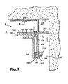
- the shutter 720 is disposed on the profile 100, between two shims 200 (only one visible on the figure 7 ).
- the blade 721 is secured to the profile 100 by means of a screw 9.
- a rod 730 has a first end 731 fixed, for example by means of a screw 10 to the shim 200.
- a second end 732 of the 730 rod bears against the blade 721.
- the second end 732 of the rod 730 can press the shutter 720 against the profile, so that the shutter 720 remains in position on the profile 100.
- provision may be made to replace the rod 730 by a spring screw for fixing the blade 721 to the profile 100.
- the profile 100, or first profile supports a false ceiling, such as a false suspended ceiling, and a second section (not shown), mounted on the first section or on the false ceiling, is provided with shutters 700, 710 or 720.
- the second section can be arranged on any external contour of the false ceiling, or only on a partial outer contour of said false ceiling.
- the profile 100 is provided with another example of a removable flap 740.
- the flap 740 is snapped onto the lower end 126 of a flange 125 of the profile 100, similarly to the flap 700 of the example shown in FIGS. figures 1 and 4 .
- the inner face 741 of the flap 740 directed towards the wall 2 and extending parallel to said wall 2, is provided with a plurality of redents 742, or striations, forming the protuberances extending perpendicular to the wall 2.
- the redents 742 are arranged one below the other.
- the number of teeth 742 may vary from one flap 740 to another, as well as the spacing between two consecutive flutes 742, and their length.
- length of the sheaves 742 is meant the size of said shears in a direction perpendicular to the wall 2.
- the spacing between the sheaves 742, and / or the length of the sheaves 742 can be constant or variable.
- the blade 743 of the flap 740 is flexible and can be partially folded, so that the free end 744 of the blade 743 can be retained by the teeth 742.
- the air passage 6 is more or less reduced.
- superior redent we mean a redent situated above a given redent, and by redent lower, we mean a redent located below the redent considered.
- Retention means that the end 744 of the blade 743 is held in position at the redent 742 considered.
- a gap is provided between two successive redes 742, said gap being able to receive and hold the free end 744 of the blade 743. It is also possible to provide on the teeth 742 and on the free end 744 of the blade 743 mechanical coupling means for securing non-irreversibly said end 744 on a redent 742 desired.
- the number of sheaves 742 can vary according to the flaps 740, and in particular according to the length of the blade 743.
- a flap 740 can thus completely obstruct the passage 6, for example when the free end 744 of the blade 743 is not retained by the teeth 742 and the blade 743 extends towards the wall 2.
- This same flap 740 when the blade 743 is folded, so for example that the free end 744 is housed in a gap formed between two redents 742 consecutive, reduces the width of the passage 6 air.
- the user can easily vary the air passage 6, and therefore the air flow rate, by changing the position of the free end 744 of the blade 743 relative to the teeth 742.
Landscapes
- Engineering & Computer Science (AREA)
- Architecture (AREA)
- Civil Engineering (AREA)
- Structural Engineering (AREA)
- Electromagnetism (AREA)
- Physics & Mathematics (AREA)
- General Engineering & Computer Science (AREA)
- Building Environments (AREA)
- Installation Of Indoor Wiring (AREA)
- Residential Or Office Buildings (AREA)
- Conveying And Assembling Of Building Elements In Situ (AREA)
- Duct Arrangements (AREA)
- Hooks, Suction Cups, And Attachment By Adhesive Means (AREA)
- Vehicle Interior And Exterior Ornaments, Soundproofing, And Insulation (AREA)
- Jib Cranes (AREA)
- Details Or Accessories Of Spraying Plant Or Apparatus (AREA)
- Supports Or Holders For Household Use (AREA)
Priority Applications (3)
| Application Number | Priority Date | Filing Date | Title |
|---|---|---|---|
| SI200531309T SI1745183T1 (sl) | 2004-05-11 | 2005-05-10 | Priprava za drĺ˝anje spuĺ äśenega stropa ali dvignjenega poda |
| PL05762464T PL1745183T3 (pl) | 2004-05-11 | 2005-05-10 | Urządzenie podtrzymujące sufit podwieszany lub podwyższoną podłogę |
| CY20111100580T CY1111635T1 (el) | 2004-05-11 | 2011-06-16 | Συστημα στηριξης ψευδοροφης ή ψευδοπατωματος |
Applications Claiming Priority (2)
| Application Number | Priority Date | Filing Date | Title |
|---|---|---|---|
| FR0450907A FR2870273B1 (fr) | 2004-05-11 | 2004-05-11 | Dispositif de maintien d'un faux plafond ou faux plancher. |
| PCT/FR2005/050308 WO2005113910A2 (fr) | 2004-05-11 | 2005-05-10 | Dispositif de maintien d'un faux plafond ou faux plancher |
Publications (2)
| Publication Number | Publication Date |
|---|---|
| EP1745183A2 EP1745183A2 (fr) | 2007-01-24 |
| EP1745183B1 true EP1745183B1 (fr) | 2011-03-16 |
Family
ID=34947287
Family Applications (1)
| Application Number | Title | Priority Date | Filing Date |
|---|---|---|---|
| EP05762464A Expired - Lifetime EP1745183B1 (fr) | 2004-05-11 | 2005-05-10 | Dispositif de maintien d'un faux plafond ou faux plancher |
Country Status (15)
| Country | Link |
|---|---|
| US (1) | US8146315B2 (pl) |
| EP (1) | EP1745183B1 (pl) |
| AT (1) | ATE502169T1 (pl) |
| CA (1) | CA2566365C (pl) |
| CY (1) | CY1111635T1 (pl) |
| DE (1) | DE602005026930D1 (pl) |
| DK (1) | DK1745183T3 (pl) |
| ES (1) | ES2363731T3 (pl) |
| FR (1) | FR2870273B1 (pl) |
| MA (1) | MA28577B1 (pl) |
| PL (1) | PL1745183T3 (pl) |
| PT (1) | PT1745183E (pl) |
| RU (1) | RU2337217C1 (pl) |
| SI (1) | SI1745183T1 (pl) |
| WO (1) | WO2005113910A2 (pl) |
Cited By (1)
| Publication number | Priority date | Publication date | Assignee | Title |
|---|---|---|---|---|
| EA035162B1 (ru) * | 2016-08-03 | 2020-05-08 | Прогресс Профайлз Спа | Фальшпол, содержащий профилированный элемент |
Families Citing this family (17)
| Publication number | Priority date | Publication date | Assignee | Title |
|---|---|---|---|---|
| EP2599924B1 (en) * | 2010-07-28 | 2016-07-06 | Volvo Construction Equipment AB | Apparatus for fixing the rear glass of an operator cab on construction machinery |
| US8316600B2 (en) | 2010-12-06 | 2012-11-27 | Usg Interiors, Llc | Wall conforming suspended ceiling molding |
| US9353532B2 (en) * | 2013-08-02 | 2016-05-31 | Jpcm Llc | Deck drainage systems |
| US9353534B2 (en) * | 2013-08-02 | 2016-05-31 | Jpcm Llc | Deck drainage systems |
| FR3055342A1 (fr) | 2016-08-24 | 2018-03-02 | Jean Marc Scherrer | Profile d'accroche permettant le passage d'air et ensemble de plafond comprenant un tel profile |
| US10590662B2 (en) | 2016-09-06 | 2020-03-17 | Jim Peterson | Deck drainage systems |
| US20180171645A1 (en) * | 2016-12-15 | 2018-06-21 | Old World Oddities LLC | Modular construction systems |
| FR3062864A1 (fr) * | 2017-02-13 | 2018-08-17 | Cme Dwc | Procede de montage d'un revetement souple tendu sur un cadre de fixation et cadre de fixation pour la mise en oeuvre dudit procede |
| CN107313548B (zh) * | 2017-06-26 | 2022-09-23 | 浙江未来加电子商务有限公司 | 可调式墙挂装置 |
| FR3074822B1 (fr) * | 2017-12-11 | 2020-09-04 | Normalu | Lisse a parties detachables |
| US10876305B2 (en) * | 2019-05-23 | 2020-12-29 | Usg Interiors, Llc | Building perimeter systems |
| US10900243B2 (en) * | 2019-05-24 | 2021-01-26 | Terry Koethe | Two-piece trim assembly for siding on buildings |
| FR3106350B1 (fr) * | 2020-01-22 | 2022-01-28 | Ruhlmann Rene Philippe | Systeme de diffusion d'air parietal |
| RU2742420C1 (ru) * | 2020-08-10 | 2021-02-05 | Сергей Юрьевич ПУГАЧЕВ | Узел стыковки устройства крепления подвесного потолка |
| CN115584838A (zh) * | 2022-07-07 | 2023-01-10 | 宁波弘威电梯有限公司 | 电梯井道框架吊顶的安装结构及安装方法 |
| CN116623874A (zh) * | 2023-06-09 | 2023-08-22 | 中建二局第一建筑工程有限公司 | 一种用于装配式住宅的钢柱安装结构及其安装方法 |
| WO2025048677A1 (ru) * | 2023-08-29 | 2025-03-06 | Сергей Юрьевич Пугачев | Периметральный элемент узла стыковки подвесного потолка |
Family Cites Families (14)
| Publication number | Priority date | Publication date | Assignee | Title |
|---|---|---|---|---|
| US2239508A (en) * | 1938-12-15 | 1941-04-22 | Burgess Battery Co | Air-distributing apparatus for ventilating systems |
| US3319558A (en) * | 1965-01-04 | 1967-05-16 | Sunbeam Lighting Company | Partition wall header with ventilating air divider |
| US3403614A (en) * | 1967-04-28 | 1968-10-01 | Bendix Corp | Environmental enclosure with ceiling air plenum |
| US3543669A (en) * | 1968-11-18 | 1970-12-01 | Baldwin Ehret Hill Inc | Ventilating ceiling construction |
| US3577904A (en) * | 1969-04-14 | 1971-05-11 | Robert R Lambert | Suspended ceiling integrated air distribution system |
| US3894366A (en) * | 1970-11-23 | 1975-07-15 | Robert W Arnett | Drapery pocket |
| US3831506A (en) * | 1972-11-21 | 1974-08-27 | Hunter Douglas International | Composite ventilation member for ceiling coverings |
| CH569163A5 (pl) * | 1973-05-23 | 1975-11-14 | Burgess Architectural Products | |
| US4672887A (en) * | 1983-12-19 | 1987-06-16 | Sproul Sr Fred C | Combination valance and conditioned air admission and return ducts |
| FR2597906A1 (fr) * | 1986-04-25 | 1987-10-30 | Bouttier Dominique | Dispositif d'accrochage pour faux plafond souple tendu |
| DE3933110A1 (de) * | 1989-10-04 | 1991-04-11 | Juergen Schmitt | Vorrichtung zur halterung von deckenplatten an einer wand |
| US5881502A (en) * | 1997-05-23 | 1999-03-16 | Tamlyn; John Thomas | Ventilation strip for veneer finished buildings |
| FR2815112B1 (fr) * | 2000-10-09 | 2004-07-16 | Alain Triboix | Dispositif de climatisation mettant en oeuvre un faux plafond et assurant une diffusion d'air le long des parois |
| RU2181421C1 (ru) * | 2001-05-18 | 2002-04-20 | Торгушников Василий Константинович | Устройство для крепления подвесного потолка |
-
2004
- 2004-05-11 FR FR0450907A patent/FR2870273B1/fr not_active Expired - Fee Related
-
2005
- 2005-05-10 DK DK05762464.5T patent/DK1745183T3/da active
- 2005-05-10 DE DE602005026930T patent/DE602005026930D1/de not_active Expired - Lifetime
- 2005-05-10 US US11/568,642 patent/US8146315B2/en not_active Expired - Fee Related
- 2005-05-10 WO PCT/FR2005/050308 patent/WO2005113910A2/fr not_active Ceased
- 2005-05-10 SI SI200531309T patent/SI1745183T1/sl unknown
- 2005-05-10 CA CA2566365A patent/CA2566365C/en not_active Expired - Fee Related
- 2005-05-10 RU RU2006143640/03A patent/RU2337217C1/ru not_active IP Right Cessation
- 2005-05-10 EP EP05762464A patent/EP1745183B1/fr not_active Expired - Lifetime
- 2005-05-10 PT PT05762464T patent/PT1745183E/pt unknown
- 2005-05-10 ES ES05762464T patent/ES2363731T3/es not_active Expired - Lifetime
- 2005-05-10 AT AT05762464T patent/ATE502169T1/de active
- 2005-05-10 PL PL05762464T patent/PL1745183T3/pl unknown
-
2006
- 2006-11-10 MA MA29445A patent/MA28577B1/fr unknown
-
2011
- 2011-06-16 CY CY20111100580T patent/CY1111635T1/el unknown
Cited By (1)
| Publication number | Priority date | Publication date | Assignee | Title |
|---|---|---|---|---|
| EA035162B1 (ru) * | 2016-08-03 | 2020-05-08 | Прогресс Профайлз Спа | Фальшпол, содержащий профилированный элемент |
Also Published As
| Publication number | Publication date |
|---|---|
| EP1745183A2 (fr) | 2007-01-24 |
| DE602005026930D1 (de) | 2011-04-28 |
| MA28577B1 (fr) | 2007-05-02 |
| FR2870273B1 (fr) | 2008-04-11 |
| CY1111635T1 (el) | 2015-10-07 |
| RU2337217C1 (ru) | 2008-10-27 |
| ATE502169T1 (de) | 2011-04-15 |
| SI1745183T1 (sl) | 2011-08-31 |
| CA2566365C (en) | 2011-04-19 |
| US8146315B2 (en) | 2012-04-03 |
| PT1745183E (pt) | 2011-07-01 |
| US20080127585A1 (en) | 2008-06-05 |
| DK1745183T3 (da) | 2011-07-04 |
| FR2870273A1 (fr) | 2005-11-18 |
| WO2005113910A2 (fr) | 2005-12-01 |
| RU2006143640A (ru) | 2008-06-20 |
| PL1745183T3 (pl) | 2011-10-31 |
| CA2566365A1 (en) | 2005-12-01 |
| WO2005113910A3 (fr) | 2006-04-13 |
| ES2363731T3 (es) | 2011-08-12 |
Similar Documents
| Publication | Publication Date | Title |
|---|---|---|
| EP1745183B1 (fr) | Dispositif de maintien d'un faux plafond ou faux plancher | |
| CA2202205C (fr) | Dispositif de roulement pour ouvrant coulissant de porte, fenetre ou analogue | |
| EP2761110A1 (fr) | Dispositif pour la fixation d'une dalle a une structure, par exemple une structure porteuse ou une structure intermédiaire d'un batiment, et plafond suspendu a une structure | |
| CA2973677A1 (fr) | Dispositif de fixation de panneau solaire | |
| EP3957817B1 (fr) | Structure de volet roulant et méthode de montage | |
| BE512172A (pl) | ||
| EP1031787A1 (fr) | Projecteur à occulteur aéré | |
| EP1741872B1 (fr) | Système de volet roulant encastrable et non apparent | |
| EP2672191A1 (fr) | Bac à condensats et appareil de traitement d'air muni d'un tel bac | |
| EP1336716B1 (fr) | Dispositif de fixation d'une sous-face sur un caisson tunnel de volet roulant | |
| FR3097895A1 (fr) | Patte de positionnement d’un tube de volet roulant, support de volet roulant, sous ensemble de montage comprenant une telle patte de positionnement, installation comprenant un volet roulant et procédé de montage de volet roulant | |
| EP2843314B1 (fr) | Dispositif de circulation d'air notamment pour hotte de cheminée et hotte de cheminée équipée d'un tel dispositif | |
| EP0643192B1 (fr) | Ensemble de caisson de volet roulant | |
| EP2075888A1 (fr) | Support d'appareillages électriques multipostes à montage horizontal et vertical, ensemble comportant un tel support muni d'une entretoise, et appareillage électrique comportant un tel ensemble équipé de mécanismes d'appareillage | |
| EP1059415B1 (fr) | Enrouleur de sangle, mécanisme de manoeuvre d'un volet ou store roulant comprenant un tel enrouleur et procédé de fabrication d'un tel enrouleur | |
| EP2631897A1 (fr) | Dispositif d'affichage à toile tendue | |
| EP4040052B1 (fr) | Système à ensemble de modules chauffants | |
| FR2788555A1 (fr) | Ensemble bloc, porte, fenetre ou analogue-volet roulant | |
| FR2988753A1 (fr) | Dispositif de montage et de fixation de panneaux de revetement | |
| EP2575182A1 (fr) | Dispositif de fixation d'au moins un module photovoltaïque sur une structure porteuse, panneau photovoltaïque et ensemble comprenant au moins deux panneaux photovoltaïques équipés chacun d'un tel dispositif | |
| FR2956151A1 (fr) | Cale de reglage pour la fin de course d'enroulement d'un volet roulant, et installation de volet roulant comportant de telles cales de reglage | |
| BE1005857A3 (fr) | Coffret pour appareils electriques, a habillage exterieur presentant a etancheite au moins une plaque amovible. | |
| WO2018134493A1 (fr) | Dispositif d'obturation d'entree d'air de face avant de vehicule automobile | |
| EP3059376A1 (fr) | Procédé d'assemblage d'une installation de fermeture ou de protection solaire, système de support et installation | |
| FR2667633A1 (fr) | Panneau de cloison et cloison demontable comprenant au moins un tel panneau. |
Legal Events
| Date | Code | Title | Description |
|---|---|---|---|
| PUAI | Public reference made under article 153(3) epc to a published international application that has entered the european phase |
Free format text: ORIGINAL CODE: 0009012 |
|
| 17P | Request for examination filed |
Effective date: 20061102 |
|
| AK | Designated contracting states |
Kind code of ref document: A2 Designated state(s): AT BE BG CH CY CZ DE DK EE ES FI FR GB GR HU IE IS IT LI LT LU MC NL PL PT RO SE SI SK TR |
|
| DAX | Request for extension of the european patent (deleted) | ||
| 17Q | First examination report despatched |
Effective date: 20071214 |
|
| GRAP | Despatch of communication of intention to grant a patent |
Free format text: ORIGINAL CODE: EPIDOSNIGR1 |
|
| GRAS | Grant fee paid |
Free format text: ORIGINAL CODE: EPIDOSNIGR3 |
|
| GRAA | (expected) grant |
Free format text: ORIGINAL CODE: 0009210 |
|
| AK | Designated contracting states |
Kind code of ref document: B1 Designated state(s): AT BE BG CH CY CZ DE DK EE ES FI FR GB GR HU IE IS IT LI LT LU MC NL PL PT RO SE SI SK TR |
|
| REG | Reference to a national code |
Ref country code: GB Ref legal event code: FG4D Free format text: NOT ENGLISH |
|
| REG | Reference to a national code |
Ref country code: CH Ref legal event code: EP |
|
| REG | Reference to a national code |
Ref country code: IE Ref legal event code: FG4D |
|
| REF | Corresponds to: |
Ref document number: 602005026930 Country of ref document: DE Date of ref document: 20110428 Kind code of ref document: P |
|
| REG | Reference to a national code |
Ref country code: DE Ref legal event code: R096 Ref document number: 602005026930 Country of ref document: DE Effective date: 20110428 |
|
| REG | Reference to a national code |
Ref country code: RO Ref legal event code: EPE |
|
| REG | Reference to a national code |
Ref country code: NL Ref legal event code: T3 |
|
| REG | Reference to a national code |
Ref country code: PT Ref legal event code: SC4A Free format text: AVAILABILITY OF NATIONAL TRANSLATION Effective date: 20110616 |
|
| REG | Reference to a national code |
Ref country code: DK Ref legal event code: T3 |
|
| REG | Reference to a national code |
Ref country code: SE Ref legal event code: TRGR |
|
| REG | Reference to a national code |
Ref country code: CH Ref legal event code: NV Representative=s name: ARNOLD & SIEDSMA AG |
|
| REG | Reference to a national code |
Ref country code: ES Ref legal event code: FG2A Ref document number: 2363731 Country of ref document: ES Kind code of ref document: T3 Effective date: 20110812 |
|
| REG | Reference to a national code |
Ref country code: GR Ref legal event code: EP Ref document number: 20110401424 Country of ref document: GR Effective date: 20110714 |
|
| REG | Reference to a national code |
Ref country code: SK Ref legal event code: T3 Ref document number: E 9538 Country of ref document: SK |
|
| REG | Reference to a national code |
Ref country code: PL Ref legal event code: T3 |
|
| REG | Reference to a national code |
Ref country code: HU Ref legal event code: AG4A Ref document number: E011924 Country of ref document: HU |
|
| PLBE | No opposition filed within time limit |
Free format text: ORIGINAL CODE: 0009261 |
|
| STAA | Information on the status of an ep patent application or granted ep patent |
Free format text: STATUS: NO OPPOSITION FILED WITHIN TIME LIMIT |
|
| 26N | No opposition filed |
Effective date: 20111219 |
|
| REG | Reference to a national code |
Ref country code: DE Ref legal event code: R097 Ref document number: 602005026930 Country of ref document: DE Effective date: 20111219 |
|
| PGFP | Annual fee paid to national office [announced via postgrant information from national office to epo] |
Ref country code: GB Payment date: 20140527 Year of fee payment: 10 Ref country code: EE Payment date: 20140423 Year of fee payment: 10 Ref country code: MC Payment date: 20140418 Year of fee payment: 10 Ref country code: LT Payment date: 20140418 Year of fee payment: 10 Ref country code: IE Payment date: 20140527 Year of fee payment: 10 |
|
| PGFP | Annual fee paid to national office [announced via postgrant information from national office to epo] |
Ref country code: SI Payment date: 20140425 Year of fee payment: 10 Ref country code: BG Payment date: 20140528 Year of fee payment: 10 Ref country code: SE Payment date: 20140530 Year of fee payment: 10 Ref country code: PT Payment date: 20140422 Year of fee payment: 10 Ref country code: TR Payment date: 20140424 Year of fee payment: 10 Ref country code: CH Payment date: 20140527 Year of fee payment: 10 Ref country code: DE Payment date: 20140529 Year of fee payment: 10 Ref country code: CZ Payment date: 20140425 Year of fee payment: 10 Ref country code: IT Payment date: 20140522 Year of fee payment: 10 Ref country code: SK Payment date: 20140422 Year of fee payment: 10 Ref country code: LU Payment date: 20140604 Year of fee payment: 10 Ref country code: ES Payment date: 20140526 Year of fee payment: 10 Ref country code: AT Payment date: 20140423 Year of fee payment: 10 Ref country code: IS Payment date: 20140422 Year of fee payment: 10 Ref country code: GR Payment date: 20140529 Year of fee payment: 10 Ref country code: RO Payment date: 20140422 Year of fee payment: 10 Ref country code: NL Payment date: 20140526 Year of fee payment: 10 Ref country code: FI Payment date: 20140529 Year of fee payment: 10 |
|
| PGFP | Annual fee paid to national office [announced via postgrant information from national office to epo] |
Ref country code: BE Payment date: 20140530 Year of fee payment: 10 Ref country code: DK Payment date: 20140602 Year of fee payment: 10 Ref country code: HU Payment date: 20140424 Year of fee payment: 10 Ref country code: PL Payment date: 20140422 Year of fee payment: 10 |
|
| PGFP | Annual fee paid to national office [announced via postgrant information from national office to epo] |
Ref country code: CY Payment date: 20140424 Year of fee payment: 10 |
|
| PGFP | Annual fee paid to national office [announced via postgrant information from national office to epo] |
Ref country code: FR Payment date: 20140530 Year of fee payment: 10 |
|
| REG | Reference to a national code |
Ref country code: PT Ref legal event code: MM4A Free format text: LAPSE DUE TO NON-PAYMENT OF FEES Effective date: 20151110 |
|
| REG | Reference to a national code |
Ref country code: DE Ref legal event code: R119 Ref document number: 602005026930 Country of ref document: DE |
|
| REG | Reference to a national code |
Ref country code: DK Ref legal event code: EBP Effective date: 20150531 |
|
| REG | Reference to a national code |
Ref country code: LT Ref legal event code: MM4D Effective date: 20150510 |
|
| REG | Reference to a national code |
Ref country code: CH Ref legal event code: PL |
|
| REG | Reference to a national code |
Ref country code: AT Ref legal event code: MM01 Ref document number: 502169 Country of ref document: AT Kind code of ref document: T Effective date: 20150510 Ref country code: EE Ref legal event code: MM4A Ref document number: E005756 Country of ref document: EE Effective date: 20150531 |
|
| GBPC | Gb: european patent ceased through non-payment of renewal fee |
Effective date: 20150510 |
|
| PG25 | Lapsed in a contracting state [announced via postgrant information from national office to epo] |
Ref country code: CH Free format text: LAPSE BECAUSE OF NON-PAYMENT OF DUE FEES Effective date: 20150531 Ref country code: LT Free format text: LAPSE BECAUSE OF NON-PAYMENT OF DUE FEES Effective date: 20150510 Ref country code: EE Free format text: LAPSE BECAUSE OF NON-PAYMENT OF DUE FEES Effective date: 20150531 Ref country code: IT Free format text: LAPSE BECAUSE OF NON-PAYMENT OF DUE FEES Effective date: 20150510 Ref country code: LU Free format text: LAPSE BECAUSE OF NON-PAYMENT OF DUE FEES Effective date: 20150510 Ref country code: GR Free format text: LAPSE BECAUSE OF NON-PAYMENT OF DUE FEES Effective date: 20151208 Ref country code: FI Free format text: LAPSE BECAUSE OF NON-PAYMENT OF DUE FEES Effective date: 20150510 Ref country code: LI Free format text: LAPSE BECAUSE OF NON-PAYMENT OF DUE FEES Effective date: 20150531 Ref country code: MC Free format text: LAPSE BECAUSE OF NON-PAYMENT OF DUE FEES Effective date: 20150601 |
|
| REG | Reference to a national code |
Ref country code: SK Ref legal event code: MM4A Ref document number: E 9538 Country of ref document: SK Effective date: 20150510 |
|
| REG | Reference to a national code |
Ref country code: NL Ref legal event code: MM Effective date: 20150601 |
|
| REG | Reference to a national code |
Ref country code: IE Ref legal event code: MM4A |
|
| REG | Reference to a national code |
Ref country code: FR Ref legal event code: ST Effective date: 20160129 |
|
| PG25 | Lapsed in a contracting state [announced via postgrant information from national office to epo] |
Ref country code: IS Free format text: LAPSE BECAUSE OF FAILURE TO SUBMIT A TRANSLATION OF THE DESCRIPTION OR TO PAY THE FEE WITHIN THE PRESCRIBED TIME-LIMIT Effective date: 20151201 Ref country code: CZ Free format text: LAPSE BECAUSE OF NON-PAYMENT OF DUE FEES Effective date: 20150510 Ref country code: SK Free format text: LAPSE BECAUSE OF NON-PAYMENT OF DUE FEES Effective date: 20150510 Ref country code: CY Free format text: LAPSE BECAUSE OF NON-PAYMENT OF DUE FEES Effective date: 20150510 Ref country code: HU Free format text: LAPSE BECAUSE OF NON-PAYMENT OF DUE FEES Effective date: 20150511 Ref country code: SI Free format text: LAPSE BECAUSE OF NON-PAYMENT OF DUE FEES Effective date: 20150511 Ref country code: RO Free format text: LAPSE BECAUSE OF NON-PAYMENT OF DUE FEES Effective date: 20150510 Ref country code: PT Free format text: LAPSE BECAUSE OF NON-PAYMENT OF DUE FEES Effective date: 20151110 Ref country code: SE Free format text: LAPSE BECAUSE OF NON-PAYMENT OF DUE FEES Effective date: 20150511 Ref country code: AT Free format text: LAPSE BECAUSE OF NON-PAYMENT OF DUE FEES Effective date: 20150510 |
|
| REG | Reference to a national code |
Ref country code: SI Ref legal event code: KO00 Effective date: 20160112 |
|
| REG | Reference to a national code |
Ref country code: GR Ref legal event code: ML Ref document number: 20110401424 Country of ref document: GR Effective date: 20151208 |
|
| PG25 | Lapsed in a contracting state [announced via postgrant information from national office to epo] |
Ref country code: BG Free format text: LAPSE BECAUSE OF NON-PAYMENT OF DUE FEES Effective date: 20160331 Ref country code: NL Free format text: LAPSE BECAUSE OF NON-PAYMENT OF DUE FEES Effective date: 20150601 Ref country code: DK Free format text: LAPSE BECAUSE OF NON-PAYMENT OF DUE FEES Effective date: 20150531 Ref country code: IE Free format text: LAPSE BECAUSE OF NON-PAYMENT OF DUE FEES Effective date: 20150510 Ref country code: DE Free format text: LAPSE BECAUSE OF NON-PAYMENT OF DUE FEES Effective date: 20151201 Ref country code: GB Free format text: LAPSE BECAUSE OF NON-PAYMENT OF DUE FEES Effective date: 20150510 |
|
| PG25 | Lapsed in a contracting state [announced via postgrant information from national office to epo] |
Ref country code: FR Free format text: LAPSE BECAUSE OF NON-PAYMENT OF DUE FEES Effective date: 20150601 |
|
| REG | Reference to a national code |
Ref country code: ES Ref legal event code: FD2A Effective date: 20160627 |
|
| PG25 | Lapsed in a contracting state [announced via postgrant information from national office to epo] |
Ref country code: ES Free format text: LAPSE BECAUSE OF NON-PAYMENT OF DUE FEES Effective date: 20150511 |
|
| PG25 | Lapsed in a contracting state [announced via postgrant information from national office to epo] |
Ref country code: PL Free format text: LAPSE BECAUSE OF NON-PAYMENT OF DUE FEES Effective date: 20150510 |
|
| PG25 | Lapsed in a contracting state [announced via postgrant information from national office to epo] |
Ref country code: BE Free format text: LAPSE BECAUSE OF NON-PAYMENT OF DUE FEES Effective date: 20150531 |
|
| PG25 | Lapsed in a contracting state [announced via postgrant information from national office to epo] |
Ref country code: TR Free format text: LAPSE BECAUSE OF NON-PAYMENT OF DUE FEES Effective date: 20150510 |