EP1745217B2 - Unterdruck-haltevorrichtung - Google Patents
Unterdruck-haltevorrichtung Download PDFInfo
- Publication number
- EP1745217B2 EP1745217B2 EP05706754.8A EP05706754A EP1745217B2 EP 1745217 B2 EP1745217 B2 EP 1745217B2 EP 05706754 A EP05706754 A EP 05706754A EP 1745217 B2 EP1745217 B2 EP 1745217B2
- Authority
- EP
- European Patent Office
- Prior art keywords
- suction
- suction base
- holding device
- contact pressure
- type holding
- Prior art date
- Legal status (The legal status is an assumption and is not a legal conclusion. Google has not performed a legal analysis and makes no representation as to the accuracy of the status listed.)
- Expired - Lifetime
Links
Images


Classifications
-
- F—MECHANICAL ENGINEERING; LIGHTING; HEATING; WEAPONS; BLASTING
- F16—ENGINEERING ELEMENTS AND UNITS; GENERAL MEASURES FOR PRODUCING AND MAINTAINING EFFECTIVE FUNCTIONING OF MACHINES OR INSTALLATIONS; THERMAL INSULATION IN GENERAL
- F16B—DEVICES FOR FASTENING OR SECURING CONSTRUCTIONAL ELEMENTS OR MACHINE PARTS TOGETHER, e.g. NAILS, BOLTS, CIRCLIPS, CLAMPS, CLIPS OR WEDGES; JOINTS OR JOINTING
- F16B47/00—Suction cups for attaching purposes; Equivalent means using adhesives
Definitions
- the invention relates to a vacuum holding device for fixing objects on fastening surfaces.
- Vacuum holding devices are known, for example, as squeegee attachments.
- the suction feet of such squeegee attachments are made of an elastic material, such as rubber or plastic.
- the technical effect of such suction feet is that a chamber forms between the hollow interior and the fastening surface to which the suction foot is to be attached.
- the air is pressed out of the chamber by pressing the squeegee onto the mounting surface; it escapes between the sealing edge of the squeegee and the mounting surface.
- the resilient elasticity of the squeegee creates a negative pressure in the chamber, which sucks the squeegee onto the mounting surface.
- the known vacuum holding devices aim for good adhesion to smooth mounting surfaces. Adhesion to less smooth, rough surfaces is a problem. Such less smooth surfaces are, for example, the more or less horizontal top covers of dashboards in motor vehicles, the so-called dashboard.
- a vacuum holding device which has a lid made of a resilient material on a rubber-elastic suction pad.
- the convex lid shape changes into a concave shape.
- the lid returns to its convex shape and thus spaces the center of the suction pad from the contact surface, so that a vacuum is formed between the suction cup and the contact surface.
- Such a vacuum holding device differs from the present invention in that the soft suction pad itself cannot develop any force directed away from the contact surface after the contact pressure has been released. This can be disadvantageous for the adherence of the vacuum holding device, because the extent of the vacuum is determined solely by the restoring force of the cover.
- a vacuum holding device with a bell-shaped suction pad and cover is known, in which differently than after GB 491,991
- the center of the suction pad and the lid are not immovable but are slidably connected to each other.
- a screw shaft sits on a disc-like, stiff metal plate that is inserted into the suction pad.
- the metal plate has holes.
- the center of the suction pad is spaced from the storage surface for generating the vacuum by means of a head with a threaded hole placed on the cover.
- This vacuum holding device also has no stabilizing structure with arms and the rigid metal plate introduced into the suction pad cannot develop any additional restoring force in response to the decreasing contact pressure because it cannot be elastically deformed.
- a vacuum holding device for fixing to fastening surfaces having the features of independent claim 1 and the use according to claim 18.
- the advantage of the invention is that the pressure used for fixing is not only applied from the center piece, but also in a targeted manner via the squeegee wall, and thus a better pushing away of the air from the vacuum chamber is possible. This is particularly important with increasing elasticity / softness of the squeegee. Based on this construction, the adhesion is surprisingly good, even on rough mounting surfaces. After the vacuum holding device has been fixed, the contact pressure transmitters, in cooperation with the central piece and the pressing means, maintain a tension on the central piece away from the fastening surface.
- the contact pressure transmitters are elastically deformable in height and consist, for example, of an annular bead or individual knobs arranged in a ring.
- the pressure medium which presses against the bulge or the knobs, consists of a cover that presses against the outside via the contact pressure transmitters against the wall of the squeegee.
- the bead or the knobs are optionally provided on the outside of the squeegee or on the side of the cover which increases the pressure, and which faces the squeegee. The same pressure transfer is achieved in both cases.
- the contact pressure transmitters are, however, preferably an integral part of the squeegee wall and, moreover, are preferably made of the same material. In the relaxed state, the contact pressure transmitters can only be connected to the pressure medium or only to the squeegee wall. These are preferably in contact with the pressure means and with the squeegee wall even when the vacuum holding device is at rest.
- the contact pressure also has a shape-stabilizing effect the inherently elastic wall of the squeegee.
- the squeegee and preferably also the contact pressure transmitters consist in particular of a material with a Shore hardness less than 18 (Shore A in each case), for example between 10 and 18, preferably in the range from 11 to 14. Shore hardnesses in the vicinity of are particularly favorable 12 (ie +/- 0.5). Shore hardnesses so low ensure that the sealing edge adapts well to unevenness in the fastening surface and accordingly seals well.
- the sealing edge corresponds to the contact surface of the squeegee on the mounting surface.
- Elastic materials such as rubber and in particular thermoplastic elastomers have proven to be particularly suitable materials for the squeegee. Suitable materials are e.g. Styrene block copolymers, styrene block terpolymers (styrene-ethylene-butylene-styrene block polymers) and styrene-diene polymers.
- a very soft material of the squeegee has the disadvantage that the dimensional stability suffers.
- a stabilizing framework for example in the form of a stabilizing spider, is embedded in the material of the squeegee with spider arms extending from a central piece.
- the shape of the stabilizing spider determines the bell shape of the suction cup.
- the stabilization frame is springy.
- the arms of the stabilization scaffold can be angled backwards. If plastic is used, it should be relatively temperature stable. In particular, they are fiber-reinforced polyolefins and in particular glass-fiber-reinforced polypropylene.
- the stabilizing scaffold has arms extending from the central piece, which are possibly connected to one another and cover at least half, preferably at least three quarters, of the radius of the suction cup.
- the spider arms of the stabilization scaffold starting from the central piece are each provided at the top with at least one terminal spacer, which is essentially embedded on all sides in the soft-elastic material with the Shore hardness (according to DIN 53505) less than 18 and approximately the height of the coating has the spider arms.
- the spacers facilitate the injection molding of the squeegee and fix the arms in the injection mold.
- three sealing lips are provided, which are concentric and which are located on the decreasing diameters towards the center piece.
- a lid which is placed over the squeegee and is connected to the central part of the squeegee, serves to depress the bead.
- the pressure means or the cover can also be part of the object to be fastened or its holder, for example a holder for a mobile telephone.
- the lid is made of a non-elastic solid material and is preferably concave, e.g. as a partial surface of a spherical surface, and more preferably by a contact pressure acting centrally on the lid, as exerted by fingers, so deformable that the concave shape flattens out and the lid center strives back into the tension-free, concave original shape with a restoring force.
- the lid can have spacers on the inside at the outer edge in the form of one or more circular or part-circular ribs or punctiform knobs which, when fitted, are supported against the outer suction cup wall and prevent the lid from tipping.
- the cover essentially completely covers the squeegee. Possibly. it may be desirable that the squeegee is not covered at the very edge and forms a joint-like edge along which it can be wiped well.
- the concave cover which has been elastically deformed by the contact pressure, spaces the center piece further under tension with a restoring force from the fastening surface.
- the cover is preferably non-detachably connected to the central piece of the squeegee by a snap connection
- the mounting device for objects to be held has, for example, a central screw connection which connects the cover to the central piece of the suction base and also serves to fasten objects.
- the mounting device in particular the screw connection, preferably has a ball joint to which objects can be attached.
- the ball joint preferably consists of a ball arranged on the screw connection and a ball basket fitting thereon, which carries a fastening piece for objects.
- Ball and ball cage can be fixed against each other by adjusting screws, for example in the form of grub screws. The ball can be easily adjusted to get the best view.
- the screw connection can have a fastening plate with which the cover can be pressed onto the central piece of the suction foot.
- a Velcro fastener not shown, can be provided on the fastening plate, on which the object can be fixed with the counterpart of the Velcro fastener. This is a variant of the ball joint.
- Ball joint and Velcro have another useful purpose, in order to create the possibility in the event of a mounting below the windshield on the upper valve cover that the assembled objects detach themselves from the vacuum holding device in the event of a collision.
- the vacuum holding device can also be provided with a claw washer, possibly with additional mounting devices, screwed onto the cover.
- the cover is essentially round, but has edge zones distributed approximately evenly over the circumference at a smaller distance from the center of the cover and edge zones at a greater distance from the center of the cover.
- the claw washer is placed on the edge zones with a smaller distance from the center of the cover and is fixed by turning in the direction of the edge zones at a greater distance from the center of the cover by engaging claws in the other edge zones of the cover.
- latching devices are provided, via which the claw washer is initially rotatably guided, in order to finally be locked in a rotationally secure manner in the anchoring position.
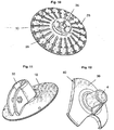
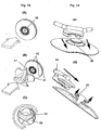
- FIG. 11 is the holder for a rod part of the lid and in Figure 12 Part of a claw plate placed on the lid.
- the Figure 13 illustrates how the claw plate is placed on the vacuum holding device (A) attached to a wall (B) and remains in a suitable position for the two hooks by turning over locking teeth (C).
- the Figure 14 shows how a double hook is placed on a spring clamp shoe and is fixed by means of two lower spring cheeks which snap into the shoe.
- the clamping shoe is rotatably supported by locking holes in the plate and corresponding knobs under the shoe.
- the vacuum holding device 1 has a suction base 2.
- Fig. 1 it can be seen that the squeegee 2 has a mounting device 4 in the center.
- a contact pressure transmitter 8 is provided on the outside 6 of the squeegee wall 7 between the mounting device 4 and the sealing edge 5 of the squeegee 2.
- This contact pressure transducer 8 is shown as an annularly deformable annular bead; it can also consist of individual knobs. The knob version is not shown.
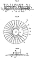
- FIG. 2 shows how Fig. 2 shows, the suction base 2 is hollow on its bottom 9 like a bell. The result is a vacuum chamber 30.
- a stabilizing structure in the form of a stabilizing spider 10 is embedded in the suction foot wall 7.
- the stabilizing spider 10 is in Fig. 4 shown in top view; it is made of plastic or metal. At its center, it consists of a preferably cylindrical central piece 11 and spider arms 13 projecting therefrom towards the spider edge 12.
- the spider arms 13 are separated from one another by means of separating slots 14 which extend from the central piece 11 to the spider edge 12. However, it is also possible to make the separating slots 14 only from about half (14a), starting from a solid piece 15, as in FIG Fig. 4 is indicated for some spider arms.
- Fig. 5 the stabilizing spider 10 is shown in side view. One recognizes the central piece 11 and the spider arms 13. The spider arms 13 can be bent up and down against a restoring force in the direction of the rest position. The stabilizing spider 10 is also in the Fig. 10 shown. In Figure 10 are additional Spacers 26 and a snap-in recess 35 can be seen in the central piece 11.
- the stabilizing spider 10 can be clearly seen inside the squeegee 2, because the parts 11, 13 after Fig. 5 are shown in dashed lines with thicker lines.
- On the underside 9 of the suction base 2 one can see three concentric sealing lips 16 which protrude downwards and which are located in the area of the sealing edge 5.
- the sealing lips 16 run concentrically to the central piece 11 and to smaller diameters towards the central piece.
- the material of the squeegee 2 injected around the stabilizing spider 10 is very soft. Its Shore hardness (type A) is in the range from 10 to 18, preferably 11 to 14, in particular in the vicinity of 12. Thus, the squeegee 2 also sucks very well on rough fastening surfaces 17. The shape stability and the resilient elasticity of the squeegee body is ensured by the injected stabilizing spider 10.
- Fig. 6 shows a cover completely covering the suction base 2 as a pressure means 18.
- a fastening screw 20 is inserted through a central opening 19 in the pressure means 18 Fig. 7 put through.
- This fastening screw 20 consists of a head plate 21 and a screw shaft 22 with an external thread 23.
- An inner bore 24 of the central piece 11 has an internal thread 25.
- the pressure medium 18 is fixed with the fastening screw 20 via the suction base 2 Fig. 2 put up.
- the pressure means 18 is curved upwards and is pressed down by means of the fastening screw 20 so that the screw shaft 22 can be screwed into the internal thread 25 of the inner bore 24 of the central piece 11.
- Fig. 3 it can be seen that the head plate 21 presses the pressure means 18 onto the central piece 11.
- the depressed middle part 28 of the squeegee tends to tip up the edge region 29. But this prevents the bead 8, which holds down the edge region 29.
- the sealing lips 16 are thus pressed securely against the mounting surface 17.
- the vacuum chamber 30 which is formed between the underside 9 of the suction base 2 and the fastening surface 17, a negative pressure has developed, but this is only so high that damage to the fastening surface 17 is avoided.
- the vacuum chamber 30 has a very flat expansion.
- Fig. 9 shows a section through cover 18 and squeegee 2.
- the snap-in recess 35 with abutment 37 for the barb 36, the snap-in flange 34 and the pressure booster 8 can be seen particularly well.
- the locking knobs 38 engage in corresponding recesses in a claw washer 39, not shown, as exemplarily shown in FIG Fig. 12 is shown, a. So that this does not tilt when the cover 18 is fixed, support grooves 27 are provided which are supported on the suction base wall 7.
- the support grooves 27 can also be designed as support knobs.
- Objects can be attached to the vacuum holder device. This can be done either by means of the fastening screw 20 screwed into the internal thread 25 or a Velcro fastener, not shown.
- Fig. 8 shows a further variant, which consists of a ball 31 connected to the fastening screw 20 and a ball basket 32 placed on the ball 31, which carries a fastening socket 33.
- a rod holder which can be clamped by means of a machine screw is shown as mounting device 4.
- the attachment piece 33 is designed as a rod sleeve, applied directly to the cover 18 and has a lateral stabilizing strut.
- a claw washer 39 can also be placed on the flat cover 18.
- the not completely round lid has three bulges (edge zones 42) in which the claws 40 of the claw disk 39 can be fixed by turning.
- the claw washer 39 is placed by aligning the claws 40 with three corresponding indentations (edge zones 41).
- the process of locking the claw washer 39 is shown in FIG Figure 13 (Sequence A to C) shown schematically.
- the arrow on the lid 18 indicates the position at the top.
- Fig. 14 shows that the mounting device 4 can alternatively also be fixed by means of a shoe which can be rotated about a dome with spring cheeks 43.
- the double hook 44 is secured against rotation by latching devices 38 when the spring cheeks 43 engage in a recess in the interior of the shoe downward.
Landscapes
- Engineering & Computer Science (AREA)
- General Engineering & Computer Science (AREA)
- Mechanical Engineering (AREA)
- Hooks, Suction Cups, And Attachment By Adhesive Means (AREA)
- Container, Conveyance, Adherence, Positioning, Of Wafer (AREA)
- Manipulator (AREA)
- Supplying Of Containers To The Packaging Station (AREA)
- Jigs For Machine Tools (AREA)
- Physical Vapour Deposition (AREA)
Description
- Die Erfindung bezieht sich auf eine Unterdruck-Haltevorrichtung zum Festlegen von Gegenständen an Befestigungsoberflächen.
- Unterdruck-Haltevorrichtungen sind beispielsweise als Saugfußbefestigungen bekannt. Die Saugfüße solcher Saugfußbefestigungen bestehen aus einem elastischen Material, wie Gummi oder Kunststoff. Der technische Effekt solcher Saugfüße besteht darin, dass sich zwischen dem hohlen Innenraum und der Befestigungsoberfläche, an der der Saugfuß zu befestigen ist, beim Ansetzen eine Kammer ausbildet. Die Luft wird aus der Kammer durch ein Andrücken des Saugfußes an die Befestigungsoberfläche herausgepresst; sie entweicht zwischen dem Dichtrand des Saugfußes und der Befestigungsoberfläche. Bei nachlassendem Andruck stellt sich durch die rückfedernde Elastizität des Saugfußes in der Kammer ein Unterdruck ein, der den Saugfuß an der Befestigungsoberfläche festsaugt.
- Die bekannten Unterdruck-Haltevorrichtungen zielen auf eine gute Haftung an glatten Befestigungsoberflächen ab. Das Anhaften an weniger glatten, rauen Oberflächen stellt ein Problem dar. Solche weniger glatten Oberflächen sind beispielsweise die mehr oder weniger horizontalen oberen Abdeckungen von Armaturentafeln in Kraftfahrzeugen, das so genannte Armaturenbrett.
- Aus der
GB 491,991 - Aus der
GB 1,084,559 GB 491,991 - Viele der bekannten Haftsaugvorrichtungen mit Glockenform haben den Nachteil, dass durch die Rückstellkraft des Saugnapfes in Glockenform bei nachlassendem Unterdruck der Winkel zwischen Dichtrand und Auflagefläche größer wird, hieraus eine ungebremste auch radial nach innen gerichtete Rückstellkraft resultiert und die Haftsaugvorrichtung abfällt.
- Es ist Aufgabe der Erfindung, eine Unterdruck-Haltevorrichtung zu schaffen, die auch an rauen Befestigungsoberflächen sicher, fest und lang anhaltend haftet.
- Die Aufgabe wird erfindungsgemäß gelöst durch eine Unterdruck-Haltevorrichtung zum Festlegen an Befestigungsoberflächen aufweisend die Merkmale des unabhängigen Anspruchs 1 und die Verwendung gemäß Anspruch 18.
- Bevorzugte Ausführungsformen sind Gegenstand der Unteransprüche oder nachfolgend beschrieben.
- Der Vorteil der Erfindung besteht darin, dass der dem Festlegen dienende Andruck nicht nur vom Zentralstück aus, sondern gezielt auch über die Saugfußwand aufgebracht wird und damit ein besseres Wegdrücken der Luft aus der Unterdruckkammer möglich ist. Dies ist besonders wichtig bei zunehmende Elastizität /Weichheit des Saugfußes. Die Haftfähigkeit ist auf Basis dieser Konstruktion auch an rauen Befestigungsoberflächen erstaunlich gut. Nach dem Festlegen der Unterdruck-Haltevorrichtung halten die Anpressdrucküberträger in Zusammenwirkung mit dem Zentralstück und dem Andruckmittel eine Zugspannung am Zentralstück von der Befestigungsoberfläche weg aufrecht.
- Die Anpressdruck-Überträger sind elastisch in der Höhe verformbar und bestehen z.B. aus einem ringförmigen Wulst oder einzelnen ringförmig angeordneten Noppen. Das Andruckmittel, das gegen den Wulst oder die Noppen drückt, besteht aus einem Deckel, der andrückend von außen über die Anpressdruck-Überträger gegen die Wand des Saugfußes wirkt.
- Die Wulst oder die Noppen sind wahlweise an der Außenseite des Saugfußes oder an der zum Saugfuß gewandten Seite des den Andruck verstärkenden Deckels vorgesehen. In beiden Fällen wird die gleiche Druckübertragung erzielt.
- Die Anpressdruck-Übertrager sind aber bevorzugt integraler Bestandteil der Saugfußwand und weiterhin bevorzugt aus dem selben Material hergestellt. Die Anpressdruck-Überträger können im entspannten Zustand nur mit dem Andruckmittel oder nur mit der Saugfußwand in Verbindung stehen. Bevorzugt stehen diese auch im Ruhezustand der Unterdruckhaltevorrichtung mit dem Andruckmittel und mit der Saugfußwand in Berührung.
- Wenn sich der Ring der Anpressdruck-Überträger vom Zentralstück aus gesehen auf einem bestimmten Radius befindet, der z.B. vom Zentralstück aus gesehen etwa von 1/4 bis 5/6, insbesondere von 1/3 bis 2/3, des Vollradiuses des Saugnapfes reicht, dann wirkt sich der Anpressdruck zusätzlich formstabilisierend auf die in sich elastische Wand des Saugfußes aus.
- Der Saugfuß und vorzugsweise auch die Anpressdruck-Überträger bestehen insbesondere aus einem Material mit einer Shore-Härte kleiner 18 (jeweils Shore A), z.B. zwischen 10 und 18, vorzugsweise im Bereich von 11 bis 14. Besonders günstig sind Shore-Härten im Umfeld von 12 (d.h. +/- 0,5). So geringe Shore-Härten sorgen dafür, dass sich der Dichtrand an Unebenheiten der Befestigungsfläche gut anpasst und dementsprechend gut abdichtet. Der Dichtrand entspricht der Auflagefläche des Saugfußes auf der Befestigungsoberfläche.
- Als besonders gut geeignete Materialien für den Saugfuß haben sich elastische Materialien wie Gummi und insbesondere thermoplastische Elastomere erwiesen. Geeignete Materialien sind z.B. Styrol-Block-Copolymere, Styrol-Block-Terpolymere (Styrol-Ethylen-Butylen-Styrol-Blockpolymere) und Styrol-Dien-Polymere.
- Ein sehr weiches Material des Saugfußes hat den Nachteil, dass die Formstabilität darunter leidet. Um dem Saugfuß diese Formstabilität dennoch zu verleihen, ist in das Material des Saugfußes ein Stabilisierungsgerüst, z.B. in Form einer Stabilisierungsspinne, mit von einem Zentralstück ausgehenden Spinnenarmen eingebettet. Die Form der Stabilisierungsspinne bestimmt die Glockenform des Saugnapfes.
- Das Stabilisierungsgerüst ist federungsfähig. Die Arme des Stabilisierungsgerüstes sind aber rückfedernd abwinkelbar. Wenn Kunststoff zum Einsatz kommt, dann sollte relativ temperaturstabil sein. Insbesondere handelt es sich um faserverstärkte Polyolefine und insbesondere um glasfaserverstärktes Polypropylen.
- Das Stabilisierungsgerüst weist vom Zentralstück ausgehende Armen auf, die ggf. untereinander verbunden sind und zumindest den halben vorzugsweise zumindest dreiviertel des Radius des Saugfußes überstreichen.
- Die vom Zentralstück ausgehenden Spinnenarme des Stabilisierungsgerüstes sind nach einer bevorzugten Ausführungsform oben jeweils mit zumindest einem endständigen Abstandshalter versehen, der im wesentlichen allseitig in das weichelastische Material mit der Shore-Härte (nach DIN 53505) kleiner 18 einbettet ist und etwa die Höhe der Beschichtung auf den Spinnearmen hat. Die Abstandshalter erleichtern die Spritzguss-Herstellung des Saugfußes und fixieren die Arme in der Spritzgussform.
- Am Dichtrand zur Unterseite des Saugfußes hin sind z.B. drei Dichtlippen vorgesehen, die konzentrisch sind und die sich zum Zentralstück hin auf sich verkleinernden Durchmessern befinden.
- Zum Niederdrücken des Wulstes dient ein über den Saugfuß gestülpter Deckel, der mit dem Zentralstück des Saugfußes verbunden ist. Das Andruckmittel bzw. der Deckel können auch Teil des zu befestigenden Gegenstandes bzw. dessen Halterung sein, etwa einer Halterung für ein mobiles Telefon.
- Der Deckel besteht aus einem in sich selbst nicht elastischen festen Material und ist vorzugsweise konkav, z.B. als Teilfläche einer Kugeloberfläche, und weiter bevorzugt durch einen mittig auf den Deckel wirkenden Anpressdruck, wie von Fingern ausgeübt, so verformbar, dass die konkave Form sich verflacht und die Deckelmitte mit eine Rückstellkraft in die spannungslose konkave Ursprungsform zurückstrebt.
- Der Deckel kann innen am Außenrand Abstandshalter in Form einer oder mehrerer kreisförmiger oder teilkreisförmiger Rippen oder punktförmiger Noppen aufweisen, die sich im angebrachten Zustand gegen die äußere Saugfußwand abstützen und ein Kippeln des Deckels verhindern.
- Der Deckel deckt den Saugfuß im wesentlichen vollständig ab. Ggf. kann es gewünscht sein, dass der Saugfuß am äußersten Rand nicht überdeckt wird und eine fugenartige Kante bildet entlang derer gut gewischt werden kann.
- Nach Erliegen des Anpressdruckes beabstandet der durch den Anpreßdruck elastisch deformierte konkave Deckel das Zentralstück unter Spannung mit einer Rückstellkraft weiter von der Befestigungsoberfläche.
- Der Deckel ist bevorzugt mit dem Zentralstück des Saugfußes durch eine Einrastverbindung unlösbar verbunden
- Die Montageeinrichtung für zu haltende Gegenstände weist z.B. eine zentrale Schraubenverbindung auf, die den Deckel mit dem Zentralstück des Saugfußes verbindet und auch der Befestigung von Gegenständen dient.
- Um die Ausrichtung mit der Haltevorrichtung befestigter Gegenstände in Hinsicht auf optimale Sichtbarkeit zu ermöglichen, weist die Montageeinrichtung, insbesondere die Schraubverbindung, vorzugsweise ein Kugelgelenk auf, an dem Gegenstände anbringbar sind.
- Das Kugelgelenk besteht vorzugsweise aus einer an der Schraubverbindung angeordneten Kugel und einem darauf passenden Kugelkorb, der einen Befestigungsstutzen für Gegenstände trägt. Kugel und Kugelkorb können gegeneinander durch Stellschrauben, z.B. in Form von Madenschrauben fixiert sein. Über den Kugelkorb lässt sich auf einfache Weise die optimale Sichteinstellung erzielen. Die Schraubverbindung kann einen Befestigungsteller aufweisen, mit dem der Deckel auf das Zentralstück des Saugfußes drückbar ist. An dem Befestigungsteller kann ein nicht dargestellter Klettverschluß vorgesehen sein, an dem der Gegenstand mit dem Gegenstück des Klettverschlusses festsetzbar ist. Dies ist eine Variante zum Kugelgelenk.
- Kugelgelenk und Klettverschluss verfolgen noch den weiteren sinnvollen Zweck, um im Falle einer Montage unterhalb der Windschutzscheibe auf der oberen Armaturenabdeckung die Möglichkeit zu schaffen, dass die montierten Gegenstände sich im Falle einer Kollision von der Unterdruck-Haltevorrichtung ablösen.
- Die Unterdruck-Haltevorrichtung kann auch mit einer Klauenscheibe mit ggf. weiteren Montageeinrichtungen auf dem Deckel aufgedreht versehen sein. Hierzu ist der Deckel im Wesentlichen rund ausgebildet, hat aber etwa gleichmäßig über den Umfang verteilt Randzonen mit geringerem Abstand zum Deckelmittelpunkt und Randzonen mit größerem Abstand zum Deckelmittelpunkt. Die Klauenscheibe wird auf die Randzonen mit geringerem Abstand zum Deckelmittelpunkt gesetzt und durch Drehen in Richtung der Randzonen mit größerem Abstand zum Deckelmittelpunkt durch Eingreifen von Krallen in die weiteren Randzonen des Deckels festlegt.
- Um ein Verdrehen der festgesetzten Klauenscheibe zu verhindern, sind Einrastvorrichtungen vorgesehen über die die Klauenscheibe anfänglich drehbar geführt ist, um schließlich in der Verankerungsposition einrastend verdrehsicher festgelegt zu sein.
- Im Folgenden wird der Gegenstand der Erfindung anhand der
Figuren 1 bis 14 beispielhaft erläutert. Es zeigen: -
Fig.1 in Draufsicht den Saugfuß einer Unterdruck-Haltevorrichtung, die auch an rauen Befestigungsoberflächen haften kann, -
Fig. 2 den Saugfuß der Unterdruck-Haltevorrichtung nachFig. 1 in Seitenansicht. -
Fig. 3 die Unterdruck-Haltevorrichtung in montiertem Zustand im Schnitt, -
Fig. 4 in Draufsicht die in das Material des Saugfußes der Unterdruck-Haltevorrichtung eingebrachte, formstabilisierende Einlage in Form einer Stabilisierungsspinne mit einem Zentralstück und von diesem ausgehende Spinnenarme, -
Fig. 5 die Stabilisierungsspinne nachFig. 4 im Rohzustand in Seitenansicht, -
Fig. 6 einen Andruckverstärkerdeckel für die Montage der Unterdruck-Haltevorrichtung, -
Fig. 7 eine Montageschraube für die Unterdruck-Haltevorrichtung, mit der diese an einer Befestigungsoberfläche festgelegt wird, in Seitenansicht, -
Fig. 8 eine abgewandelte Montageschraube mit einem Kugelgelenk für die Befestigung eines Gegenstandes. -
Fig. 9 einen Schnitt durch den Saugfuß und den Deckel. Das Zentralstück weist eine Ausnehmung für ein Einrastelement auf, um Deckel und Zentralstück gegeneinander festzulegen. Stützrillen verhindern ein Kippeln des aufgesetzten Deckels. -
Fig. 10 eine dreidimensionale Darstellung der Stabilisierungsspinne mit Abstandshaltern auf den Spinnenarmen und einer Ausnehmung für ein Einrastelement im Zentralstück. - In
Figur 11 und 12 sind verschiedene Montageeinrichtungen als Stangenhalterung abgebildet. InFig. 11 ist die Aufnahme für eine Stange Teil des Deckels und inFigur 12 Teil einer auf den Deckel aufgesetzten Klauenplatte. - Die
Figur 13 verdeutlicht wie die Klauenplatte auf die an einer Wand befestigte Unterdruckhaltevorrichtung (A) aufgesetzt wird (B) und in einer für die beiden Haken geeignet ausgerichteten Position durch Drehen über Rastzähne (C) verharrt. - Die
Figur 14 zeigt wie ein Doppelhaken auf einen Federklemmschuh aufgesetzt wird und mittel zweier unterer im Schuh einrastender Federwangen fixiert wird. Der Klemmschuh ist durch Rastlöcher in der Platte und entsprechende Noppen unter dem Schuh verdrehsicher gelagert. - Die Unterdruck-Haltevorrichtung 1 nach den Figuren weist einen Saugfuß 2 auf. In
Fig. 1 ist zu erkennen, dass der Saugfuß 2 im Zentrum eine Montageeinrichtung 4 aufweist. Zwischen der Montageeinrichtung 4 und dem Dichtrand 5 des Saugfußes 2 ist an der Außenseite 6 der Saugfußwand 7 ein Anpressdruck-Überträger 8 vorgesehen. Dieser Anpressdruck-Übertrager 8 ist als in der Höhe elastisch verformbarer Ringwulst dargestellt; er kann auch aus einzelnen Noppen bestehen. Die Noppenvariante ist nicht dargestellt. - Wie
Fig. 2 zeigt, ist der Saugfuß 2 an seiner Unterseite 9 hohl ausgebildet wie eine Glocke. Es ergibt sich dabei eine Unterdruckammer 30. In die Saugfußwand 7 ist ein Stabilisierungsgerüst in Form einer Stabilisierungsspinne 10 eingebettet. Die Stabilisierungsspinne 10 ist inFig. 4 in Draufsicht dargestellt; sie besteht aus Kunststoff oder Metall. In ihrem Zentrum besteht sie aus einem vorzugsweise zylindrischen Zentralstück 11 und von diesem zum Spinnenrand 12 hin abstehenden Spinnenarmen 13. Die Spinnenarme 13 sind mittels Trennschlitzen 14 voneinander separiert, die sich vom Zentralstück 11 aus bis zum Spinnenrand 12 erstrecken. Es ist aber auch möglich, die Trennschlitze 14 nur etwa ab der Hälfte (14a), ausgehend von einem Vollstück 15, anzubringen, wie inFig.4 für einige Spinnenarme angedeutet ist. - In
Fig. 5 ist die Stabilisierungsspinne 10 in Seitenansicht dargestellt. Man erkennt das Zentralstück 11 und die Spinnenarme 13. Die Spinnenarme 13 sind auf und nieder biegbar gegen eine Rückstellkraft in Richtung auf die Ruheposition. Die Stabilisierungsspinne 10 ist ebenfalls in derFig. 10 dargestellt. InFigur 10 sind zusätzlich Abstandshalter 26 und eine Einrastausnehmung 35 im Zentralstück 11 zu sehen. - Betrachtet man die
Fig. 2 , dann ist die Stabilisierungsspinne 10 innerhalb des Saugfußes 2 deutlich zu erkennen, weil die Teile 11, 13 nachFig. 5 mit dickeren Linien gestrichelt dargestellt sind. An der Unterseite 9 des Saugfußes 2 erkennt man drei konzentrische Dichtlippen 16, die nach unten vorstehen und die sich im Bereich des Dichtrandes 5 befinden. Die Dichtlippen 16 verlaufen konzentrisch zum Zentralstück 11 und auf sich zum Zentralstück hin verkleinernden Durchmessern. - Das um die Stabilisierungsspinne 10 gespritzte Material des Saugfußes 2 ist sehr weich. Seine Shore-Härte (Typ A) liegt im Bereich von 10 bis 18, vorzugsweise 11 bis 14, insbesondere im Umfeld von 12. Damit saugt sich der Saugfuß 2 auch an raue Befestigungsoberflächen 17 sehr gut an. Die Formstabilität und die rückfedernde Elastizität des Saugfuß-Körpers wird durch die eingespritzte Stabilisierungsspinne 10 gewährleistet.
-
Fig. 6 zeigt einen den Saugfuß 2 vollständig abdeckenden Deckel als Andruckmittel 18. Zur Montage wird durch eine zentrale Öffnung 19 in dem Andruckmittel 18 eine Befestigungsschraube 20 nachFig. 7 hindurch gesteckt. Diese Befestigungsschraube 20 besteht aus einer Kopfplatte 21 und einem Schraubenschaft 22 mit Außengewinde 23. Eine Innenbohrung 24 des Zentralstückes 11 weist ein Innengewinde 25 auf. Das Andruckmittel 18 wird mit der Befestigungsschraube 20 über den Saugfuß 2 nachFig. 2 gestülpt. Das Andruckmittel 18 ist nach oben gewölbt und wird mittels der Befestigungsschraube 20 niedergedrückt, damit der Schraubenschaft 22 in das Innengewinde 25 der Innenbohrung 24 des Zentralstückes 11 eingeschraubt werden kann. - Aus
Fig. 3 ist zu erkennen, dass die Kopfplatte 21 das Andruckmittel 18 auf das Zentralstück 11 drückt. Der niedergedrückte Mittelteil 28 des Saugfußes ist bestrebt, den Randbereich 29 hochzukippen. Dies verhindert aber der Wulst 8, der den Randbereich 29 niederhält. Die Dichtlippen 16 werden also sicher gegen die Befestigungsoberfläche 17 gedrückt. In der Unterdruckkammer 30, die sich zwischen der Unterseite 9 des Saugfußes 2 und der Befestigungsoberfläche 17 ausbildet, ist ein Unterdruck entstanden, der aber nur so hoch ist, dass Beschädigungen der Befestigungsoberfläche 17 vermieden werden. Darüber hinaus hat die Unterdruckkammer 30 eine sehr flache Ausdehnung. -
Fig. 9 zeigt einen Schnitt durch Deckel 18 und Saugfuß 2. Besonders gut sind die Einrastausnehnung 35 mit Widerlager 37 für den Widerhaken 36 der Einrastflansch 34 sowie der Anpressdruckverstärker 8 zu erkennen. Die Einrastnoppen 38 greifen in entsprechende Ausnehmungen einer nicht dargestellten Klauenscheibe 39, wie sie beispielhaft inFig. 12 dargestellt ist, ein. Damit bei festgesetztem Deckel 18 dieser nicht kippelt, sind Stützrillen 27 vorgesehen, die sich auf die Saugfußwand 7 abstützen. Die Stützrillen 27 können auch als Stütznoppen ausgebildet sein. - An der Unterdruck-Haltervorrichtung lassen sich Gegenstände befestigen. Dies kann entweder mittels der in das Innengewinde 25 eingeschraubten Befestigungsschraube 20 oder eines nicht dargestellten Klettverschlusses erfolgen.
Fig. 8 zeigt eine weitere Variante, die aus einer mit der Befestigungsschraube 20 verbundenen Kugel 31 und einem auf die Kugel 31 gestülpten Kugelkorb 32 besteht, der einen Befestigungsstutzen 33 trägt. - In
Fig. 11 ist eine mittels einer Maschinenschraube klemmbare Stabhalterung als Montageeinrichtung 4 gezeigt. Der Befestigungsstutzen 33 ist als Stabhülse ausgebildet, unmittelbar auf dem Deckel 18 aufgebracht und weist eine seitliche Stabilisierungsstrebe auf. - Alternativ kann auf den flachen Deckel 18 auch eine Klauenscheibe 39 aufgesetzt sein. Der nicht völlig runde Deckel weist hierzu drei Ausbuchtungen (Randzonen 42) auf, in denen sich die Krallen 40 der Klauenscheibe 39 durch Drehen festsetzen lassen. Aufgesetzt wird die Klauenscheibe 39, indem die Krallen 40 mit drei korrespondierenden Einbuchtungen (Randzonen 41) gefluchtet werden. Der Vorgang des Festsetzens der Klauenscheibe 39 ist in
Figur 13 (Abfolge A bis C) schematisch dargestellt. Der Pfeil auf dem Deckel 18 gibt die Position oben an. -
Fig. 14 zeigt, dass die Montageeinrichtung 4 alternativ auch mittels eines um einen Dom mit Federwangen 43 drehbaren Schuhs festgelegt werden kann. Der Doppelhaken 44 wird durch Einrastvorrichtungen 38 gegen Verdrehen gesichert, wenn die Federwangen 43 in einer Versenkung im Inneren des Schuhs nach unten einrasten.
Claims (23)
- Unterdruck-Haltevorrichtung (1) zum Festlegen an Befestigungsoberflächen (17) aufweisend- einen zur Befestigungsoberfläche (17) offenen, hohlen Saugfuß (2) mit einem Zentralstück (11) und- einen Dichtrand (5), der zumindest zur Befestigungsoberfläche (17) hin, ein elastisches Material aufweist und mit dem der Saugfuß (2) auf die Befestigungsoberfläche (17) aufsetzbar ist, so dass sich zwischen der Unterseite (9) des Saugfußes (2) und der Befestigungsoberfläche (17), wenn auf diese aufgesetzt, eine nach außen gasdicht abgeschlossene Unterdruckkammer (30) ausbildet,- die Unterdruck-Haltevorrichtung (1) Anpressdruck-Überträger (8) aufweist, die elastisch in Richtung der Druckachse deformierbar sind und zwischen dem Zentralstück (11) des Saugfußes (2) und dem äußeren Dichtrand (5') am Saugfuß - beabstandet jeweils vom Zentralstück (11) und vom äußeren Dichtrand (5') - auf der Außenseite (6) der Saugfußwand (7) angeordnet sind, und- die Unterdruck-Haltevorrichtung (1) ein Andruckmittel (18) zur Übertragung des Anpressdruckes auf die Saugfußwand (7) aufweist, wobei das Andruckmittel (18) so ausgestaltet ist, dass es zumindest unter dem Anpressdruck ausgeübt auf das Zentralstück (11) in Richtung auf die Befestigungsoberfläche (17), wenn auf diese aufgesetzt, in Verbindung steht mit dem Zentralstück (11), den Anpressdruck-Überträgern (8) und über die Anpressdruck-Überträger (8) mit der Saugfußwand (7),- wobei das Andruckmittel (18), das andrückend von außen gegen die Saugfußwand (7) des Saugfußes (2) wirkt, aus einem am Zentralstück (11) befestigten Deckel besteht, der auf die Anpressdruck-Überträger (8) zumindest unter Anpressdruck einwirktdadurch gekennzeichnet, dass- ein Stabilisierungsgerüst (10) mit vom Zentralstück (11) ausgehenden Armen (13) in das Material des Saugfußes (2) eingebettet ist und die Arme (13) zumindest den halben Radius des Saugfußes (2) überstreichen und rückfedernd abwinkelbar sind.
- Unterdruck-Haltevorrichtung gemäß Anspruch 1, dadurch gekennzeichnet, dass die Anpressdruck-Überträger (8) aus einem im wesentlichen ringförmigen Wulst oder einzelnen Noppen bestehen, die unabhängig vorzugsweise im wesentlichen konzentrisch zum Zentralstück (11) angeordnet sind.
- Unterdruck-Haltevorrichtung gemäß einem der vorhergehenden Ansprüche, dadurch gekennzeichnet, dass die Anpressdruck-Überträger (8) aus einem gummielastischen Material bestehen, insbesondere mit einer Shore-Härte (nach DIN 53505) von kleiner 18, vorzugsweise zwischen 10 und 18, und unabhängig hiervon die Anpressdruck-Überträager (8) vorzugsweise integraler Teil der Außenseite (6) der Saugfußwand (7) sind und aus dem selben Material bestehen.
- Unterdruck-Haltevorrichtung gemäß einem der vorhergehenden Ansprüche, dadurch gekennzeichnet, dass das Andruckmittel (18) eine konkave Form hat, die weiter bevorzugt durch Krafteinwirkung mittig elastisch in Richtung des Zentrums deformierbar ist.
- Unterdruck-Haltevorrichtung gemäß einem der vorhergehenden Ansprüche, dadurch gekennzeichnet, dass der Deckel den Saugfuß (2) im wesentlichen überdeckt.
- Unterdruck-Haltevorrichtung gemäß einem der vorhergehenden Ansprüche, dadurch gekennzeichnet, dass das Andruckmittel (18) nach Erliegen des äußeren Anpressdruckes das Zentralstück (11) unter Spannung mit einer Rückstellkraft von der Befestigungsoberfläche (17), wenn auf diese aufgesetzt, zusätzlich beabstandet, vorzugsweise auch verursacht durch das zuvor erfolgte elastische Deformieren des Andruckmittels (18) in der Andruckmittelmitte durch den Anpressdruck.
- Unterdruck-Haltevorrichtung gemäß einem der vorhergehenden Ansprüche, dadurch gekennzeichnet, dass die Anpressdruck-Überträger (8) wahlweise an der Außenseite (6) des Saugfußes (2) oder an der zum Saugfuß (2) gewandten Seite des Andruckmittels (18) vorgesehen sind bzw. ein Teil derselben bilden.
- Unterdruck-Haltevorrichtung gemäß einem der vorhergehenden Ansprüche, dadurch gekennzeichnet, dass der Saugfuß (2) zumindest im Bereich des Dichtrandes (5), vorzugsweise auch im Bereich der Saugfußwand (7) und ggf. der ganze Saugfuß (2), für diesen Fall abgesehen vom Zentralstück (11), aus einem Material mit einer Shore-Härte (nach DIN 53505) kleiner 18, vorzugsweise zwischen 10 und 18 und insbesondere von 11 und 14 besteht.
- Unterdruck-Haltevorrichtung gemäß einem der vorhergehenden Ansprüche, dadurch gekennzeichnet, dass der Saugfuß (2) aus einem thermoplastischen Elastomer besteht bzw. dieses aufweist.
- Unterdruck-Haltevorrichtung gemäß einem der vorhergehenden Ansprüche, dadurch gekennzeichnet, dass die Arme (13) des Stabilisierungsgerüstes zumindest dreiviertel des Radius des Saugfußes überstreichen.
- Unterdruck-Haltevorrichtung gemäß Anspruch 10, dadurch gekennzeichnet, das-s das Stabilisierungsgerüst (10) aus einem federungsfähigen Material besteht.
- Unterdruck-Haltevorrichtung gemäß Anspruch 10 oder 11, dadurch gekennzeichnet, dass das Stabilisierungsgerüst(10) eine Glockenform aufweist, insbesondere in flacher Kreiskegelform.
- Unterdruck-Haltevorrichtung gemäß einem der vorhergehenden Ansprüche, dadurch gekennzeichnet, dass die vom Zentralstück(11) ausgehenden Arme (13) des Stabilisierungsgerüstes (10) oben, d.h. von der Befestigungsfläche (17) weg, wenn auf diese aufgesetzt, jeweils mit zumindest einem Abstandshalter (26) versehen sind, der im Wesentlichen allseitig in das weichelastische Material mit der Shore-Härte (nach DIN 53505) kleiner 18 eingebettet ist, der Abstandhalter etwa die Höhe der Beschichtung auf den Armen (13) hat und insbesondere ab der Mitte der Arme auf dem äußeren Rand der Arme (13) angeordnet ist.
- Unterdruck-Haltevorrichtung gemäß einem der vorhergehenden Ansprüche, dadurch gekennzeichnet, dass die Anpressdruck-Überträger (8) vom Zentralstück (11) aus gesehen in einem Radiusbereich angeordnet sind, der von 1/4 bis 5/6, insbesondere von 1/3 bis 2/3, des Vollradius des Saugnapfes reicht.
- Unterdruck-Haltevorrichtung gemäß einem der vorhergehenden Ansprüche, dadurch gekennzeichnet, dass am Dichtrand (5) auf der Unterseite (9) des Saugfußes ein, zwei oder drei umlaufende Dichtlippen (16) vorgesehen sind, die vorzugsweise konzentrisch sind, und weiter bevorzugt der Abstand von der äußeren Dichtlippe zur nächsten weiter innen liegenden zweiten Dichtlippe kleiner ist als der Abstand der zweiten Dichtlippe zur dritten Dichtlippe.
- Unterdruck-Haltevorrichtung gemäß einem der vorhergehenden Ansprüche, dadurch gekennzeichnet, dass das Andruckmittel (18) mit dem Zentralstück (11) des Saugfußes (2) lösbar verbunden ist.
- Unterdruck-Haltevorrichtung gemäß einem der vorhergehenden Ansprüche, dadurch gekennzeichnet, dass eine Montageeinrichtung (4) das Andruckmittel (18) und den Saugfuß lösbar verbindet und die Montageeinrichtung (4) vorzugsweise eine zentrale Schraubenverbindung (20) aufweist, die das Andruckmittel (18) mit dem Zentralstück (11) des Saugfußes (2) verbindet und/oder eine Befestigungsvorrichtung für Gegenstände aufnimmt.
- Verwendung eines Saugfußes (2) und eines Andruckmittels (18) als Bauteile einer Unterdruck-Haltevorrichtung (1) zum Festlegen an Befestigungsoberflächen (17), wobbei der Saugfuss (2) zur Befestigungsoberfläche (17) offen und hohl ist, mit einem Zentralstück (11) und einen Dichtrand (5), wobei der Saugfuß (2) zumindest zur Befestigungsoberfläche (17) hin, wenn auf diese aufgesetzt, ein elastisches Material aufweist mit dem der Saugfuß (2) auf die Befestigungsoberfläche (17) aufsetzbar ist, so dass sich zwischen der Unterseite (9) des Saugfußes und der Befestigungsoberfläche (17), wenn auf diese aufgesetzt, eine nach außen gasdicht abgeschlossene Unterdruckkammer (30) ausbildet, die Unterdruck-Haltevorrichtung (1) Anpressdruck-Überträger (8) aufweist, die elastisch in Richtung der Drückachse deformierbar sind und auf der Außenseite (6) der Saugfußwand (7) angeordnet sind, und in das elastische Material des Saugfußes (2) ein federungsfähiges Stabilisierungsgerüst (10) in Form einer Stabilisierungsspinne mit vom Zentralstück (11) ausgehenden Armen (13) eingebettet ist,
wobei das Andruckmittel (18), das andrückend von außen gegen die Saugfußwand (7) des Saugfußes (2) wirkt, aus einem am Zentral stück (11) befestigten Deckel besteht, der auf die Anpressdruck-Überträger (8) zumindest unter Anpressdruck einwirkt, und wobei die Unterdruck-Haltevorrichtung (1) das Andruckmittel (18) zur Übertragung des Anpressdruckes auf die Saugfußwand (7) aufweist, wobei das Andruckmittel (18) so ausgestaltet ist, dass es zumindest unter dem Anpressdruck ausgeübt auf das Zentralstück (11) in Richtung auf die Befestigungsoberfläche (17) in Verbindung steht mit dem Zentralstück (11), den Anpressdruck-Überträgern (8) und über die Anpressdruck-Überträger (8) mit der Saugfußwand (7), und
wobei die Arme (13) und/oder das elastische Material des Saugfußes (2) weiter durch eines oder beide der Merkmale a) und/oder b) wie folgt gekennzeichnet sind:a) die Arme (13) überstreichen zumindest den halben Radius des Saugfußes (2), wobei das elastische Material des Saugfußes (2) eine Shore-Härte kleiner 18 aufweist,b) die Arme (13) des Stabilisierungsgerüstes (10) sind nach oben, d.h. von der Befestigungsfläche (17) weg, wenn auf diese aufgesetzt, jeweils mit zumindest einem Abstandshalter (26) versehen, der im Wesentlichen allseitig in das weichelastische Material des Saugfußes (2) mit der Shore-Härte (nach DIN 53505) kleiner 18 eingebettet ist und etwa die Höhe der Beschichtung auf den Armen (13) hat. - Verwendung gemäß Anspruch 18, dadurch gekennzeichnet, dass die Arme (13), untereinander verbunden sind.
- Verwendung gemäß zumindest einem der Ansprüche 18 und 19, dadurch gekennzeichnet, dass die Arme des Stabilisierungsgerüstes rückfedernd abwinkelbar sind.
- Verwendung gemäß Anspruch 18, dadurch gekennzeichnet, dass der Saugfuß (2) Anpressdruck-Überträger (8) aufweist, die integraler Bestandteil der Saugfußwand sind.
- Verwendung gemäß Anspruch 18, dadurch gekennzeichnet, dass der Saugfuß (2) eine Glockenform hat.
- Verwendung-gemäß Anspruch 18, dadurch gekennzeichnet, dass die Arme (13) zumindest dreiviertel des Radius des Saugfußes (2) überstreichen.
Priority Applications (1)
| Application Number | Priority Date | Filing Date | Title |
|---|---|---|---|
| PL05706754.8T PL1745217T5 (pl) | 2004-05-03 | 2005-02-09 | Podciśnieniowe urządzenie mocujące |
Applications Claiming Priority (2)
| Application Number | Priority Date | Filing Date | Title |
|---|---|---|---|
| DE102004022038 | 2004-05-03 | ||
| PCT/DE2005/000214 WO2005106262A1 (de) | 2004-05-03 | 2005-02-09 | Unterdruck-haltevorrichtung |
Publications (4)
| Publication Number | Publication Date |
|---|---|
| EP1745217A1 EP1745217A1 (de) | 2007-01-24 |
| EP1745217B1 EP1745217B1 (de) | 2012-04-11 |
| EP1745217B9 EP1745217B9 (de) | 2012-08-08 |
| EP1745217B2 true EP1745217B2 (de) | 2020-04-15 |
Family
ID=34961111
Family Applications (1)
| Application Number | Title | Priority Date | Filing Date |
|---|---|---|---|
| EP05706754.8A Expired - Lifetime EP1745217B2 (de) | 2004-05-03 | 2005-02-09 | Unterdruck-haltevorrichtung |
Country Status (12)
| Country | Link |
|---|---|
| US (1) | US7690610B2 (de) |
| EP (1) | EP1745217B2 (de) |
| JP (1) | JP5010469B2 (de) |
| KR (1) | KR101224210B1 (de) |
| CN (1) | CN101014775B (de) |
| AT (1) | ATE553308T1 (de) |
| CA (1) | CA2565469C (de) |
| ES (1) | ES2385989T5 (de) |
| MX (1) | MXPA06012748A (de) |
| PL (1) | PL1745217T5 (de) |
| RU (1) | RU2383786C2 (de) |
| WO (1) | WO2005106262A1 (de) |
Families Citing this family (36)
| Publication number | Priority date | Publication date | Assignee | Title |
|---|---|---|---|---|
| GB2430908B (en) * | 2005-10-04 | 2011-08-03 | Carglass Luxembourg Sarl Zug | Suction device |
| JP4862559B2 (ja) * | 2006-08-28 | 2012-01-25 | ソニー株式会社 | 吸盤 |
| JP2008106788A (ja) * | 2006-10-23 | 2008-05-08 | Scj:Kk | 吸着盤 |
| KR100977594B1 (ko) * | 2007-12-27 | 2010-08-23 | 재단법인서울대학교산학협력재단 | 흡착 유닛 |
| TW201028562A (en) * | 2009-01-21 | 2010-08-01 | Comart Corp | Combination of sucking plate |
| TWI401383B (zh) * | 2009-05-05 | 2013-07-11 | Htc Corp | 支架及其吸盤 |
| TWM387925U (en) * | 2010-02-26 | 2010-09-01 | Wistron Neweb Corp | Suction device |
| DE102010047242B4 (de) * | 2010-10-04 | 2016-08-04 | Sto Se & Co. Kgaa | Fassadensystem |
| US8348216B2 (en) * | 2010-10-21 | 2013-01-08 | Zoya, Inc. | Suction cup apparatus for attachment to porous and nonporous surfaces |
| US8584997B2 (en) * | 2010-10-21 | 2013-11-19 | Zoya, Inc. | Suction cup apparatus for attachment to porous and nonporous surfaces |
| US8783634B2 (en) * | 2011-09-30 | 2014-07-22 | Adam P. Summers | Suction device |
| US9038870B2 (en) | 2012-05-15 | 2015-05-26 | August A. JOHNSON | Head mount apparatus for hands-free video recording with an electronic device |
| TWM455786U (zh) * | 2012-07-26 | 2013-06-21 | Tru Miles Hardware Co Ltd | 吸盤吸附結構 |
| RU2587568C2 (ru) * | 2012-11-19 | 2016-06-20 | Чжуншань Тайли Хаузхолд Продактс Мэньюфэкчеринг Ко., Лтд. | Чашечная присоска с плоским каркасом |
| RU2592770C2 (ru) * | 2012-11-19 | 2016-07-27 | Чжуншань Тайли Хаузхолд Продактс Мэньюфэкчеринг Ко., Лтд. | Вакуумная присоска с чашеобразным каркасом |
| US20170130763A1 (en) * | 2013-06-05 | 2017-05-11 | Center-Plus Slawomir Lech | Grip for smooth surfaces |
| AU2014327933B2 (en) * | 2013-09-30 | 2017-01-19 | Anho Houseware Co., Ltd. Jiangmen | Suction plate and suction plate device having suction plate |
| CN103758848A (zh) * | 2014-01-16 | 2014-04-30 | 奇塑科技(江阴)有限公司 | 一种吸盘及其吸附方法 |
| WO2016068747A1 (ru) * | 2014-10-30 | 2016-05-06 | Оксана Сергеевна ШИНКАРУК | Тренажер для ягодичных мышц в домашних условиях |
| JP6327422B2 (ja) * | 2015-03-05 | 2018-05-23 | シーピーシー カンパニー,リミテッド | 吸着板 |
| CN106308418B (zh) * | 2015-06-30 | 2017-12-19 | 司徒文芳 | 一种真空吸盘 |
| CN105179440A (zh) | 2015-07-22 | 2015-12-23 | 中山市太力家庭用品制造有限公司 | 一种吸附力强的吸盘 |
| US9939006B2 (en) | 2015-10-14 | 2018-04-10 | The Boeing Company | Sealing system for fasteners |
| CN105179444B (zh) * | 2015-10-22 | 2018-01-05 | 福建美之扣家居用品有限公司 | 用于厨房料理工具的底盘固定装置 |
| US10098815B2 (en) * | 2016-02-15 | 2018-10-16 | Matthew Zerebny | Bottle support shoe with suction base |
| DE102016113259A1 (de) * | 2016-07-19 | 2018-01-25 | Karl Storz Gmbh & Co. Kg | Fußschalter für ein medizinisches Instrument |
| KR102661594B1 (ko) * | 2016-11-16 | 2024-04-30 | 삼성전자주식회사 | 진공 흡착 장치 및 그를 포함하는 전자 장치 |
| US11415166B2 (en) * | 2019-07-24 | 2022-08-16 | Decolin Inc. | Dual install suction mounting assemblies |
| DE102019123714A1 (de) * | 2019-09-04 | 2021-03-04 | Fidlock Gmbh | Verbindungsvorrichtung zum lösbaren Verbinden zweier Baugruppen |
| US20220341459A1 (en) * | 2019-09-25 | 2022-10-27 | Yatek Marin Yat Malzemeleri Sanayi Ticaret Limited Sirketi | Functional adhesive mounting apparatus set |
| CN111140587A (zh) * | 2020-01-14 | 2020-05-12 | 中山市太力家庭用品制造有限公司 | 一种吸盘及吸盘挂钩 |
| US11674545B2 (en) * | 2020-09-29 | 2023-06-13 | The Regents Of The University Of California | Suction discs for adhesion to rough, delicate, and wet surfaces |
| WO2022108871A1 (en) * | 2020-11-18 | 2022-05-27 | Tom Van Esch | Suction cup having an effortless release |
| US11434952B2 (en) | 2020-12-16 | 2022-09-06 | Matthew Spino | Object anchoring assembly |
| AU2022262313A1 (en) | 2021-04-20 | 2023-11-30 | Nhon Hoa Nguyen | Portable vacuum gripper |
| TWI784541B (zh) * | 2021-05-25 | 2022-11-21 | 啟碁科技股份有限公司 | 複合吸盤及複合吸盤支架 |
Citations (8)
| Publication number | Priority date | Publication date | Assignee | Title |
|---|---|---|---|---|
| GB437381A (en) † | 1934-04-28 | 1935-10-28 | Stephen Arnold Marples | Improvements relating to suction appliances for attachment to surfaces |
| DE1074237B (de) † | 1960-01-28 | |||
| US4133575A (en) † | 1975-11-28 | 1979-01-09 | Ever-Clean Gmbh H.W. Nixdorf | Vibration damping means for windshield |
| DE3147293A1 (de) † | 1981-11-28 | 1983-07-14 | Hans 8500 Nürnberg Mokry | Haftsaugeinrichtung |
| US5318262A (en) † | 1992-11-27 | 1994-06-07 | Adams Mfg. Corp. | Multiple layer suction holder |
| JP2001012445A (ja) † | 1999-06-30 | 2001-01-16 | Kenjiro Teramoto | カバー式吸盤 |
| JP2001208035A (ja) † | 2000-01-21 | 2001-08-03 | Kenjiro Teramoto | カバー式吸盤 |
| EP1532891A1 (de) † | 2003-11-18 | 2005-05-25 | Trisa Holding AG | Zahnbürstenkörper |
Family Cites Families (20)
| Publication number | Priority date | Publication date | Assignee | Title |
|---|---|---|---|---|
| GB491991A (en) | 1937-06-08 | 1938-09-13 | William Norman Collins | Improvements in and relating to pneumatic suction holders |
| US2940713A (en) * | 1956-05-07 | 1960-06-14 | Dusen Engineering Company Van | Vacuum cup attachment device |
| GB1084559A (en) | 1964-11-14 | 1967-09-27 | Desmo Ltd | Improvements in licence holders for vehicles |
| DE2124511B1 (de) | 1971-05-18 | 1972-05-25 | Kissing & Möllmann, 5860 Iserlohn | Saugnapf mit mehreren Dichtlippen |
| JPS4982174U (de) * | 1972-11-02 | 1974-07-16 | ||
| JPS5586113U (de) * | 1978-12-11 | 1980-06-13 | ||
| US5029786A (en) * | 1990-05-21 | 1991-07-09 | Hans Wu | Suction cup |
| US5176346A (en) * | 1991-02-11 | 1993-01-05 | Liu Bao Shen | Suction cup device |
| CN2128678Y (zh) * | 1991-03-25 | 1993-03-24 | 吴铁汉 | 强力吸盘 |
| CN2137307Y (zh) * | 1992-07-28 | 1993-06-30 | 赵崇亮 | 强力吸盘 |
| JPH09151929A (ja) | 1995-12-01 | 1997-06-10 | Nobuaki Kitamura | ナット付吸盤とスカート状の脚を持つスタビライザーを用いた、平滑面への取付け方法 |
| JPH1182437A (ja) * | 1997-09-05 | 1999-03-26 | Pop Rivet Fastener Kk | 接着ファスナー |
| JPH11315824A (ja) * | 1998-04-30 | 1999-11-16 | Kyowa Leather Cloth Co Ltd | 吸盤基体および吸盤 |
| CN2378568Y (zh) * | 1998-11-24 | 2000-05-17 | 李进丰 | 一种改进的强力吸盘 |
| DE29916197U1 (de) * | 1999-09-15 | 2000-03-23 | Ristau, Harald, 21438 Brackel | Schraub- und dübellose Befestigung in Form eines Vakuumsystems mit integrierter Gerätehalterung |
| CN2465607Y (zh) * | 2001-02-22 | 2001-12-19 | 邹德骏 | 结构改良之吸盘座 |
| US6502794B1 (en) * | 2001-06-18 | 2003-01-07 | Tzu-Kuang Ting | Hanger device with suction cup |
| CN2486769Y (zh) * | 2001-07-27 | 2002-04-17 | 梁敏聪 | 一种壁面固定座 |
| DE10204078B4 (de) * | 2002-02-01 | 2005-05-19 | Eckart Klobe | Saugglocke zur nicht-chirurgischen Korrektur von Form und/oder Funktionsleistung des Brustkastens |
| US6666420B1 (en) * | 2003-02-25 | 2003-12-23 | Jeffrey D. Carnevali | Suction cup having compact axial installation and release mechanism |
-
2005
- 2005-02-09 CA CA2565469A patent/CA2565469C/en not_active Expired - Lifetime
- 2005-02-09 AT AT05706754T patent/ATE553308T1/de active
- 2005-02-09 CN CN2005800214300A patent/CN101014775B/zh not_active Ceased
- 2005-02-09 RU RU2006141601/11A patent/RU2383786C2/ru active
- 2005-02-09 KR KR1020067025569A patent/KR101224210B1/ko not_active Expired - Fee Related
- 2005-02-09 US US11/579,404 patent/US7690610B2/en not_active Expired - Lifetime
- 2005-02-09 JP JP2007511840A patent/JP5010469B2/ja not_active Expired - Fee Related
- 2005-02-09 WO PCT/DE2005/000214 patent/WO2005106262A1/de not_active Ceased
- 2005-02-09 EP EP05706754.8A patent/EP1745217B2/de not_active Expired - Lifetime
- 2005-02-09 PL PL05706754.8T patent/PL1745217T5/pl unknown
- 2005-02-09 ES ES05706754T patent/ES2385989T5/es not_active Expired - Lifetime
- 2005-02-09 MX MXPA06012748A patent/MXPA06012748A/es unknown
Patent Citations (8)
| Publication number | Priority date | Publication date | Assignee | Title |
|---|---|---|---|---|
| DE1074237B (de) † | 1960-01-28 | |||
| GB437381A (en) † | 1934-04-28 | 1935-10-28 | Stephen Arnold Marples | Improvements relating to suction appliances for attachment to surfaces |
| US4133575A (en) † | 1975-11-28 | 1979-01-09 | Ever-Clean Gmbh H.W. Nixdorf | Vibration damping means for windshield |
| DE3147293A1 (de) † | 1981-11-28 | 1983-07-14 | Hans 8500 Nürnberg Mokry | Haftsaugeinrichtung |
| US5318262A (en) † | 1992-11-27 | 1994-06-07 | Adams Mfg. Corp. | Multiple layer suction holder |
| JP2001012445A (ja) † | 1999-06-30 | 2001-01-16 | Kenjiro Teramoto | カバー式吸盤 |
| JP2001208035A (ja) † | 2000-01-21 | 2001-08-03 | Kenjiro Teramoto | カバー式吸盤 |
| EP1532891A1 (de) † | 2003-11-18 | 2005-05-25 | Trisa Holding AG | Zahnbürstenkörper |
Also Published As
| Publication number | Publication date |
|---|---|
| RU2383786C2 (ru) | 2010-03-10 |
| PL1745217T5 (pl) | 2023-05-22 |
| US20070241246A1 (en) | 2007-10-18 |
| JP2007536475A (ja) | 2007-12-13 |
| KR101224210B1 (ko) | 2013-01-18 |
| CN101014775B (zh) | 2011-09-14 |
| RU2006141601A (ru) | 2008-06-10 |
| JP5010469B2 (ja) | 2012-08-29 |
| ES2385989T5 (es) | 2021-01-11 |
| EP1745217B9 (de) | 2012-08-08 |
| EP1745217B1 (de) | 2012-04-11 |
| US7690610B2 (en) | 2010-04-06 |
| EP1745217A1 (de) | 2007-01-24 |
| PL1745217T3 (pl) | 2012-09-28 |
| WO2005106262A1 (de) | 2005-11-10 |
| KR20070010074A (ko) | 2007-01-19 |
| CN101014775A (zh) | 2007-08-08 |
| CA2565469A1 (en) | 2005-11-10 |
| ATE553308T1 (de) | 2012-04-15 |
| CA2565469C (en) | 2013-04-16 |
| MXPA06012748A (es) | 2007-05-04 |
| ES2385989T3 (es) | 2012-08-06 |
Similar Documents
| Publication | Publication Date | Title |
|---|---|---|
| EP1745217B2 (de) | Unterdruck-haltevorrichtung | |
| EP2515714B1 (de) | Stuhl mit einer Kippvorrichtung | |
| DE3316824C2 (de) | ||
| DE10227193B4 (de) | Verbundmembran für Membranpumpen | |
| AT500571A2 (de) | Polierkissen und system | |
| DE102008032905A1 (de) | Saugflasche | |
| WO2006079129A1 (de) | Handstempel-typenaggregat sowie antriebsrad hiefür | |
| WO2018130248A1 (de) | Saugpumpe und unterdruck-haltevorrichtung mit saugpumpe und verfahren zum anbringen einer unterdruck-haltevorrichtung | |
| EP2212568A2 (de) | Saugnapfbefestiger | |
| EP0173113B1 (de) | Aussenspiegel für Kraftfahrzeuge | |
| AT413979B (de) | Trink-mundstück | |
| EP2225786B1 (de) | Ventilstopfen | |
| DE102020130034B4 (de) | Montagesitz für Druckentlastungsvorrichtung | |
| WO2001008892A1 (de) | Handstempel | |
| EP1036014B1 (de) | Abstandhalter | |
| DE112017004329B4 (de) | Elastischer Gummikörper für einen Saugnapf | |
| DE202005008469U1 (de) | Unterdruck-Haltevorrichtung | |
| EP4212745B1 (de) | Gelenkiger stellfuss mit auflageteller | |
| DE102011013298A1 (de) | Beschlag und Duschabtrennung | |
| EP4278614A1 (de) | Montageanordnung eines lautsprechers in einem kraftfahrzeug | |
| EP2484413B1 (de) | Schwingungsdämpfer, insbesondere für Alpinski | |
| DE202009008682U1 (de) | Weiche Adapterscheibe für Saugfußhalter an nicht glatten Flächen | |
| DE202016000523U1 (de) | Saughaltevorrichtung | |
| EP2759652A1 (de) | Durchgangsdachpfanne | |
| DE202010008286U1 (de) | Saugnapf |
Legal Events
| Date | Code | Title | Description |
|---|---|---|---|
| PUAI | Public reference made under article 153(3) epc to a published international application that has entered the european phase |
Free format text: ORIGINAL CODE: 0009012 |
|
| 17P | Request for examination filed |
Effective date: 20061124 |
|
| AK | Designated contracting states |
Kind code of ref document: A1 Designated state(s): AT BE BG CH CY CZ DE DK EE ES FI FR GB GR HU IE IS IT LI LT LU MC NL PL PT RO SE SI SK TR |
|
| 17Q | First examination report despatched |
Effective date: 20070411 |
|
| DAX | Request for extension of the european patent (deleted) | ||
| GRAP | Despatch of communication of intention to grant a patent |
Free format text: ORIGINAL CODE: EPIDOSNIGR1 |
|
| GRAS | Grant fee paid |
Free format text: ORIGINAL CODE: EPIDOSNIGR3 |
|
| GRAA | (expected) grant |
Free format text: ORIGINAL CODE: 0009210 |
|
| AK | Designated contracting states |
Kind code of ref document: B1 Designated state(s): AT BE BG CH CY CZ DE DK EE ES FI FR GB GR HU IE IS IT LI LT LU MC NL PL PT RO SE SI SK TR |
|
| REG | Reference to a national code |
Ref country code: GB Ref legal event code: FG4D Free format text: NOT ENGLISH |
|
| REG | Reference to a national code |
Ref country code: CH Ref legal event code: EP |
|
| REG | Reference to a national code |
Ref country code: AT Ref legal event code: REF Ref document number: 553308 Country of ref document: AT Kind code of ref document: T Effective date: 20120415 |
|
| REG | Reference to a national code |
Ref country code: IE Ref legal event code: FG4D Free format text: LANGUAGE OF EP DOCUMENT: GERMAN |
|
| REG | Reference to a national code |
Ref country code: DE Ref legal event code: R096 Ref document number: 502005012615 Country of ref document: DE Effective date: 20120606 |
|
| REG | Reference to a national code |
Ref country code: NL Ref legal event code: T3 |
|
| REG | Reference to a national code |
Ref country code: CH Ref legal event code: NV Representative=s name: TROESCH SCHEIDEGGER WERNER AG |
|
| REG | Reference to a national code |
Ref country code: ES Ref legal event code: FG2A Ref document number: 2385989 Country of ref document: ES Kind code of ref document: T3 Effective date: 20120806 |
|
| LTIE | Lt: invalidation of european patent or patent extension |
Effective date: 20120411 |
|
| REG | Reference to a national code |
Ref country code: PL Ref legal event code: T3 |
|
| PG25 | Lapsed in a contracting state [announced via postgrant information from national office to epo] |
Ref country code: LT Free format text: LAPSE BECAUSE OF FAILURE TO SUBMIT A TRANSLATION OF THE DESCRIPTION OR TO PAY THE FEE WITHIN THE PRESCRIBED TIME-LIMIT Effective date: 20120411 Ref country code: CY Free format text: LAPSE BECAUSE OF FAILURE TO SUBMIT A TRANSLATION OF THE DESCRIPTION OR TO PAY THE FEE WITHIN THE PRESCRIBED TIME-LIMIT Effective date: 20120411 Ref country code: SE Free format text: LAPSE BECAUSE OF FAILURE TO SUBMIT A TRANSLATION OF THE DESCRIPTION OR TO PAY THE FEE WITHIN THE PRESCRIBED TIME-LIMIT Effective date: 20120411 Ref country code: IS Free format text: LAPSE BECAUSE OF FAILURE TO SUBMIT A TRANSLATION OF THE DESCRIPTION OR TO PAY THE FEE WITHIN THE PRESCRIBED TIME-LIMIT Effective date: 20120811 Ref country code: FI Free format text: LAPSE BECAUSE OF FAILURE TO SUBMIT A TRANSLATION OF THE DESCRIPTION OR TO PAY THE FEE WITHIN THE PRESCRIBED TIME-LIMIT Effective date: 20120411 |
|
| PG25 | Lapsed in a contracting state [announced via postgrant information from national office to epo] |
Ref country code: PT Free format text: LAPSE BECAUSE OF FAILURE TO SUBMIT A TRANSLATION OF THE DESCRIPTION OR TO PAY THE FEE WITHIN THE PRESCRIBED TIME-LIMIT Effective date: 20120813 Ref country code: SI Free format text: LAPSE BECAUSE OF FAILURE TO SUBMIT A TRANSLATION OF THE DESCRIPTION OR TO PAY THE FEE WITHIN THE PRESCRIBED TIME-LIMIT Effective date: 20120411 Ref country code: GR Free format text: LAPSE BECAUSE OF FAILURE TO SUBMIT A TRANSLATION OF THE DESCRIPTION OR TO PAY THE FEE WITHIN THE PRESCRIBED TIME-LIMIT Effective date: 20120712 |
|
| PLBI | Opposition filed |
Free format text: ORIGINAL CODE: 0009260 |
|
| PG25 | Lapsed in a contracting state [announced via postgrant information from national office to epo] |
Ref country code: SK Free format text: LAPSE BECAUSE OF FAILURE TO SUBMIT A TRANSLATION OF THE DESCRIPTION OR TO PAY THE FEE WITHIN THE PRESCRIBED TIME-LIMIT Effective date: 20120411 Ref country code: RO Free format text: LAPSE BECAUSE OF FAILURE TO SUBMIT A TRANSLATION OF THE DESCRIPTION OR TO PAY THE FEE WITHIN THE PRESCRIBED TIME-LIMIT Effective date: 20120411 Ref country code: EE Free format text: LAPSE BECAUSE OF FAILURE TO SUBMIT A TRANSLATION OF THE DESCRIPTION OR TO PAY THE FEE WITHIN THE PRESCRIBED TIME-LIMIT Effective date: 20120411 Ref country code: DK Free format text: LAPSE BECAUSE OF FAILURE TO SUBMIT A TRANSLATION OF THE DESCRIPTION OR TO PAY THE FEE WITHIN THE PRESCRIBED TIME-LIMIT Effective date: 20120411 Ref country code: CZ Free format text: LAPSE BECAUSE OF FAILURE TO SUBMIT A TRANSLATION OF THE DESCRIPTION OR TO PAY THE FEE WITHIN THE PRESCRIBED TIME-LIMIT Effective date: 20120411 |
|
| 26 | Opposition filed |
Opponent name: ZHONGSHAN TAILI HOUSEHOLD PRODUCTS MANUFACTURING C Effective date: 20130109 |
|
| PLAX | Notice of opposition and request to file observation + time limit sent |
Free format text: ORIGINAL CODE: EPIDOSNOBS2 |
|
| REG | Reference to a national code |
Ref country code: DE Ref legal event code: R026 Ref document number: 502005012615 Country of ref document: DE Effective date: 20130109 |
|
| PLAF | Information modified related to communication of a notice of opposition and request to file observations + time limit |
Free format text: ORIGINAL CODE: EPIDOSCOBS2 |
|
| PG25 | Lapsed in a contracting state [announced via postgrant information from national office to epo] |
Ref country code: BG Free format text: LAPSE BECAUSE OF FAILURE TO SUBMIT A TRANSLATION OF THE DESCRIPTION OR TO PAY THE FEE WITHIN THE PRESCRIBED TIME-LIMIT Effective date: 20120711 |
|
| PLBB | Reply of patent proprietor to notice(s) of opposition received |
Free format text: ORIGINAL CODE: EPIDOSNOBS3 |
|
| PG25 | Lapsed in a contracting state [announced via postgrant information from national office to epo] |
Ref country code: MC Free format text: LAPSE BECAUSE OF NON-PAYMENT OF DUE FEES Effective date: 20130228 |
|
| REG | Reference to a national code |
Ref country code: IE Ref legal event code: MM4A |
|
| PG25 | Lapsed in a contracting state [announced via postgrant information from national office to epo] |
Ref country code: IE Free format text: LAPSE BECAUSE OF NON-PAYMENT OF DUE FEES Effective date: 20130209 |
|
| PLAB | Opposition data, opponent's data or that of the opponent's representative modified |
Free format text: ORIGINAL CODE: 0009299OPPO |
|
| R26 | Opposition filed (corrected) |
Opponent name: ZHONGSHAN TAILI HOUSEHOLD PRODUCTS MANUFACTURING C Effective date: 20130109 |
|
| PG25 | Lapsed in a contracting state [announced via postgrant information from national office to epo] |
Ref country code: HU Free format text: LAPSE BECAUSE OF FAILURE TO SUBMIT A TRANSLATION OF THE DESCRIPTION OR TO PAY THE FEE WITHIN THE PRESCRIBED TIME-LIMIT; INVALID AB INITIO Effective date: 20050209 Ref country code: LU Free format text: LAPSE BECAUSE OF NON-PAYMENT OF DUE FEES Effective date: 20130209 |
|
| REG | Reference to a national code |
Ref country code: FR Ref legal event code: PLFP Year of fee payment: 12 |
|
| APBM | Appeal reference recorded |
Free format text: ORIGINAL CODE: EPIDOSNREFNO |
|
| APBP | Date of receipt of notice of appeal recorded |
Free format text: ORIGINAL CODE: EPIDOSNNOA2O |
|
| APAH | Appeal reference modified |
Free format text: ORIGINAL CODE: EPIDOSCREFNO |
|
| REG | Reference to a national code |
Ref country code: FR Ref legal event code: PLFP Year of fee payment: 13 |
|
| REG | Reference to a national code |
Ref country code: FR Ref legal event code: PLFP Year of fee payment: 14 |
|
| REG | Reference to a national code |
Ref country code: DE Ref legal event code: R082 Ref document number: 502005012615 Country of ref document: DE Representative=s name: MUELLER SCHUPFNER & PARTNER PATENT- UND RECHTS, DE Ref country code: DE Ref legal event code: R081 Ref document number: 502005012615 Country of ref document: DE Owner name: SCHMIDT, PATRICK, DE Free format text: FORMER OWNERS: POETTERS, GERT, 21224 ROSENGARTEN, DE; SCHMIDT, PATRICK, 21218 SEEVETAL, DE |
|
| APBU | Appeal procedure closed |
Free format text: ORIGINAL CODE: EPIDOSNNOA9O |
|
| RAP2 | Party data changed (patent owner data changed or rights of a patent transferred) |
Owner name: SCHMIDT, PATRICK |
|
| PUAH | Patent maintained in amended form |
Free format text: ORIGINAL CODE: 0009272 |
|
| STAA | Information on the status of an ep patent application or granted ep patent |
Free format text: STATUS: PATENT MAINTAINED AS AMENDED |
|
| 27A | Patent maintained in amended form |
Effective date: 20200415 |
|
| AK | Designated contracting states |
Kind code of ref document: B2 Designated state(s): AT BE BG CH CY CZ DE DK EE ES FI FR GB GR HU IE IS IT LI LT LU MC NL PL PT RO SE SI SK TR |
|
| REG | Reference to a national code |
Ref country code: DE Ref legal event code: R102 Ref document number: 502005012615 Country of ref document: DE |
|
| REG | Reference to a national code |
Ref country code: NL Ref legal event code: FP |
|
| REG | Reference to a national code |
Ref country code: BE Ref legal event code: PD Owner name: SCHMIDT, PATRICK; DE Free format text: DETAILS ASSIGNMENT: CHANGE OF OWNER(S), CESSION, + CHANGEMENT D'ADRESSE; FORMER OWNER NAME: SCHMIDT, PATRICK Effective date: 20200528 |
|
| REG | Reference to a national code |
Ref country code: GB Ref legal event code: 732E Free format text: REGISTERED BETWEEN 20200903 AND 20200910 |
|
| REG | Reference to a national code |
Ref country code: NL Ref legal event code: PD Owner name: PATRICK SCHMIDT; DE Free format text: DETAILS ASSIGNMENT: CHANGE OF OWNER(S), ASSIGNMENT; FORMER OWNER NAME: SCHMIDT, PATRICK Effective date: 20201020 |
|
| REG | Reference to a national code |
Ref country code: ES Ref legal event code: DC2A Ref document number: 2385989 Country of ref document: ES Kind code of ref document: T5 Effective date: 20210111 |
|
| PGFP | Annual fee paid to national office [announced via postgrant information from national office to epo] |
Ref country code: TR Payment date: 20210202 Year of fee payment: 17 Ref country code: BE Payment date: 20210218 Year of fee payment: 17 |
|
| REG | Reference to a national code |
Ref country code: AT Ref legal event code: PC Ref document number: 553308 Country of ref document: AT Kind code of ref document: T Owner name: SCHMIDT, PATRICK, DE Effective date: 20211007 |
|
| REG | Reference to a national code |
Ref country code: BE Ref legal event code: MM Effective date: 20220228 |
|
| PG25 | Lapsed in a contracting state [announced via postgrant information from national office to epo] |
Ref country code: BE Free format text: LAPSE BECAUSE OF NON-PAYMENT OF DUE FEES Effective date: 20220228 |
|
| PGFP | Annual fee paid to national office [announced via postgrant information from national office to epo] |
Ref country code: NL Payment date: 20230220 Year of fee payment: 19 |
|
| PGFP | Annual fee paid to national office [announced via postgrant information from national office to epo] |
Ref country code: FR Payment date: 20230217 Year of fee payment: 19 Ref country code: ES Payment date: 20230317 Year of fee payment: 19 Ref country code: CH Payment date: 20230307 Year of fee payment: 19 Ref country code: AT Payment date: 20230215 Year of fee payment: 19 |
|
| PGFP | Annual fee paid to national office [announced via postgrant information from national office to epo] |
Ref country code: IT Payment date: 20230228 Year of fee payment: 19 Ref country code: GB Payment date: 20230221 Year of fee payment: 19 |
|
| PGFP | Annual fee paid to national office [announced via postgrant information from national office to epo] |
Ref country code: DE Payment date: 20230426 Year of fee payment: 19 |
|
| PGFP | Annual fee paid to national office [announced via postgrant information from national office to epo] |
Ref country code: PL Payment date: 20210125 Year of fee payment: 17 |
|
| REG | Reference to a national code |
Ref country code: DE Ref legal event code: R119 Ref document number: 502005012615 Country of ref document: DE |
|
| PG25 | Lapsed in a contracting state [announced via postgrant information from national office to epo] |
Ref country code: TR Free format text: LAPSE BECAUSE OF NON-PAYMENT OF DUE FEES Effective date: 20220209 |
|
| REG | Reference to a national code |
Ref country code: CH Ref legal event code: PL |
|
| REG | Reference to a national code |
Ref country code: NL Ref legal event code: MM Effective date: 20240301 |
|
| REG | Reference to a national code |
Ref country code: AT Ref legal event code: MM01 Ref document number: 553308 Country of ref document: AT Kind code of ref document: T Effective date: 20240209 |
|
| PG25 | Lapsed in a contracting state [announced via postgrant information from national office to epo] |
Ref country code: CH Free format text: LAPSE BECAUSE OF NON-PAYMENT OF DUE FEES Effective date: 20240229 |
|
| GBPC | Gb: european patent ceased through non-payment of renewal fee |
Effective date: 20240209 |
|
| PG25 | Lapsed in a contracting state [announced via postgrant information from national office to epo] |
Ref country code: AT Free format text: LAPSE BECAUSE OF NON-PAYMENT OF DUE FEES Effective date: 20240209 |
|
| PG25 | Lapsed in a contracting state [announced via postgrant information from national office to epo] |
Ref country code: CH Free format text: LAPSE BECAUSE OF NON-PAYMENT OF DUE FEES Effective date: 20240229 Ref country code: AT Free format text: LAPSE BECAUSE OF NON-PAYMENT OF DUE FEES Effective date: 20240209 |
|
| PG25 | Lapsed in a contracting state [announced via postgrant information from national office to epo] |
Ref country code: NL Free format text: LAPSE BECAUSE OF NON-PAYMENT OF DUE FEES Effective date: 20240301 |
|
| PG25 | Lapsed in a contracting state [announced via postgrant information from national office to epo] |
Ref country code: NL Free format text: LAPSE BECAUSE OF NON-PAYMENT OF DUE FEES Effective date: 20240301 |
|
| PG25 | Lapsed in a contracting state [announced via postgrant information from national office to epo] |
Ref country code: DE Free format text: LAPSE BECAUSE OF NON-PAYMENT OF DUE FEES Effective date: 20240903 |
|
| PG25 | Lapsed in a contracting state [announced via postgrant information from national office to epo] |
Ref country code: PL Free format text: LAPSE BECAUSE OF NON-PAYMENT OF DUE FEES Effective date: 20220209 |
|
| PG25 | Lapsed in a contracting state [announced via postgrant information from national office to epo] |
Ref country code: GB Free format text: LAPSE BECAUSE OF NON-PAYMENT OF DUE FEES Effective date: 20240209 |
|
| PG25 | Lapsed in a contracting state [announced via postgrant information from national office to epo] |
Ref country code: FR Free format text: LAPSE BECAUSE OF NON-PAYMENT OF DUE FEES Effective date: 20240229 |
|
| PG25 | Lapsed in a contracting state [announced via postgrant information from national office to epo] |
Ref country code: PL Free format text: LAPSE BECAUSE OF NON-PAYMENT OF DUE FEES Effective date: 20220209 Ref country code: GB Free format text: LAPSE BECAUSE OF NON-PAYMENT OF DUE FEES Effective date: 20240209 Ref country code: FR Free format text: LAPSE BECAUSE OF NON-PAYMENT OF DUE FEES Effective date: 20240229 Ref country code: DE Free format text: LAPSE BECAUSE OF NON-PAYMENT OF DUE FEES Effective date: 20240903 |
|
| PG25 | Lapsed in a contracting state [announced via postgrant information from national office to epo] |
Ref country code: IT Free format text: LAPSE BECAUSE OF NON-PAYMENT OF DUE FEES Effective date: 20240209 |
|
| REG | Reference to a national code |
Ref country code: ES Ref legal event code: FD2A Effective date: 20250331 |
|
| PG25 | Lapsed in a contracting state [announced via postgrant information from national office to epo] |
Ref country code: ES Free format text: LAPSE BECAUSE OF NON-PAYMENT OF DUE FEES Effective date: 20240210 |