EP1745690A1 - Hartobjektdetektionsverfahren und -vorrichtung für Erntemaschine - Google Patents
Hartobjektdetektionsverfahren und -vorrichtung für Erntemaschine Download PDFInfo
- Publication number
- EP1745690A1 EP1745690A1 EP06117591A EP06117591A EP1745690A1 EP 1745690 A1 EP1745690 A1 EP 1745690A1 EP 06117591 A EP06117591 A EP 06117591A EP 06117591 A EP06117591 A EP 06117591A EP 1745690 A1 EP1745690 A1 EP 1745690A1
- Authority
- EP
- European Patent Office
- Prior art keywords
- ramp
- sensing surface
- sensing
- frangible
- transport
- Prior art date
- Legal status (The legal status is an assumption and is not a legal conclusion. Google has not performed a legal analysis and makes no representation as to the accuracy of the status listed.)
- Granted
Links
Images




Classifications
-
- A—HUMAN NECESSITIES
- A01—AGRICULTURE; FORESTRY; ANIMAL HUSBANDRY; HUNTING; TRAPPING; FISHING
- A01D—HARVESTING; MOWING
- A01D75/00—Accessories for harvesters or mowers
- A01D75/18—Safety devices for parts of the machines
- A01D75/187—Removing foreign objects
-
- A—HUMAN NECESSITIES
- A01—AGRICULTURE; FORESTRY; ANIMAL HUSBANDRY; HUNTING; TRAPPING; FISHING
- A01F—PROCESSING OF HARVESTED PRODUCE; HAY OR STRAW PRESSES; DEVICES FOR STORING AGRICULTURAL OR HORTICULTURAL PRODUCE
- A01F12/00—Parts or details of threshing apparatus
- A01F12/10—Feeders
- A01F12/16—Safety devices
-
- Y—GENERAL TAGGING OF NEW TECHNOLOGICAL DEVELOPMENTS; GENERAL TAGGING OF CROSS-SECTIONAL TECHNOLOGIES SPANNING OVER SEVERAL SECTIONS OF THE IPC; TECHNICAL SUBJECTS COVERED BY FORMER USPC CROSS-REFERENCE ART COLLECTIONS [XRACs] AND DIGESTS
- Y10—TECHNICAL SUBJECTS COVERED BY FORMER USPC
- Y10S—TECHNICAL SUBJECTS COVERED BY FORMER USPC CROSS-REFERENCE ART COLLECTIONS [XRACs] AND DIGESTS
- Y10S56/00—Harvesters
- Y10S56/15—Condition responsive
-
- Y—GENERAL TAGGING OF NEW TECHNOLOGICAL DEVELOPMENTS; GENERAL TAGGING OF CROSS-SECTIONAL TECHNOLOGIES SPANNING OVER SEVERAL SECTIONS OF THE IPC; TECHNICAL SUBJECTS COVERED BY FORMER USPC CROSS-REFERENCE ART COLLECTIONS [XRACs] AND DIGESTS
- Y10—TECHNICAL SUBJECTS COVERED BY FORMER USPC
- Y10S—TECHNICAL SUBJECTS COVERED BY FORMER USPC CROSS-REFERENCE ART COLLECTIONS [XRACs] AND DIGESTS
- Y10S56/00—Harvesters
- Y10S56/24—Harvester guards
Definitions
- the present invention pertains to a foreign object (e.g., stone, piece of metal, etc.) detection method and apparatus for detecting and removing discrete hard non-frangible objects from mobile agricultural equipment.
- a foreign object e.g., stone, piece of metal, etc.
- self-propelled combine harvesters and forage harvesters are adapted with an apparatus that performs the method of detection of rocks and other discrete hard objects to permit the reliable removal of rocks and non-frangible objects from harvested crop material during crop harvesting operations.
- non-frangible objects will be used generally to refer to any hard non-frangible objects of at least a minimum size that may be picked up by a harvesting machine in a field including but not limited to stones, rocks, pieces of metal, pieces of wood, etc.
- the minimum size will be approximately three inches (76.2 cm) in length or diameter although the present invention should not be so limited. In other embodiments the minimum size may be anywhere from one inch (2.54 cm) to five (12.7 cm) or more inches in length or diameter.
- self-propelled agricultural vehicles such as combine harvesters and forage harvesters
- these vehicles are equipped with a harvesting implement, or header, that includes a reel for pulling crops into an array of blades for cutting the crop, wherein the cut crop material is pulled further into the header along a transport surface by an auger.
- the cut crop material is carried by an elevator to a threshing and separating mechanism that removes unwanted chaff material from the desired crop matter before the crop matter reaches a storage compartment carried by the vehicle.
- non-frangible objects are often pulled into the header with the crops.
- non-frangible objects e.g., stones, pieces of metal, etc.
- various methods and apparatuses have been developed to detect and remove non-frangible objects from the header before the cut crop material is carried by the elevator into the threshing and sorting mechanism.
- An exemplary stone ejecting system may include an active system which utilized some sort of an electronic sensor, such as an acoustical transducer typically in the form of a piezoelectric disc mounted in a sensing plate in conjunction with a stone trap.
- the electronic sensor responds to the characteristics of the sound, such as the amplitude and frequency, that an impacting stone generated in the sensing plate. This signal would then be transferred through an electronic circuit that filtered out the range within which the amplitude and frequency was characteristic of stones.
- the electronic circuit automatically activated a latch releasing mechanism on a door along the bottom of the in-feed housing that would pivot open to permit the stones or hard objects to be ejected from the feeder house, along with a small amount of crop material.
- An exemplary detection/ejection system includes a sensor, a sensing plate including a sensing surface, a discriminating circuit and a solenoid operated trap door.
- the sensing plate and trap door are consecutively placed along the path of harvested material travel.
- the sensor is often a piezoelectric ceramic disc linked to the sensing plate and generates signals indicative of the type of material that impacts or is currently on the sensing plate. For instance, the sensor may generate signals whenever a stone or the like impacts the sensing surface of the plate or when a stone vibrates on the sensing plate.
- signal characteristics known to be associated with non-frangible objects are known (e.g., amplitude and frequency of vibrations, signatures associated with impacting stones, pieces of metal, etc.) and the discriminating circuit is designed to distinguish characteristics of non-frangible objects from characteristics associated with harvested crop materials.
- a signal is provided to the solenoid causing the solenoid to open the trap door so that the non-frangible object is ejected from the system.
- non-frangible objects are usually mixed in with harvested crop material so that the non-frangible objects often do not make direct contact with the sensing surface.
- the harvested crop material operates as a type of muffler to stifle the signals associated with the non-frangible objects thereby making it difficult to distinguish those objects from the harvested crop materials.
- harvester and harvesting related noise make it difficult to distinguish non-frangible objects from harvested crop materials. Consequently, unless signal characteristics indicative of non-frangible objects are precisely known and the discriminating circuit is precisely tuned to pick up the non-frangible object signal characteristics, incorrect object identifications can occur which lead to either opening of the trap door when not necessary and loss of crop material or passing of non-frangible objects to the elevator and threshing mechanisms resulting in damaged equipment.
- an apparatus for use in agricultural harvesting machine comprising:
- This structure improves the chance that foreign object strike the sensing plate.
- the at least first and second ramp members include a plurality of ramp members positioned between the transport surface and the sensing surface where adjacent ramp members are separated by gaps, each ramp member including a front ramp surface that extends between a front ramp end adjacent the transport surface and a ramp member apex, the ramp member apexes positioned at a location higher than the sensing surface and proximate the sensing surface.
- each ramp member is a substantially flat member where an edge of the flat member forms the front ramp surface.
- the transport surface is formed at least in part by a flat lower surface and where the front ramp ends are substantially flush with the lower surface.
- each of the front ramp surfaces is inclined from the font ramp end to the apex.
- each of the ramp members includes a rear ramp surface that extends from the apex toward a rear ramp end where the rear ramp end is adjacent the sensing surface.
- a front ramp inclination angle is formed by the front ramp surfaces with the transport surface and a rear ramp inclination angle is formed by the rear ramp surface and the sensing surface and the front ramp inclination angle is less than the rear ramp inclination angle.
- the front ramp inclination angle is between five degrees and forty-five degrees and the rear ramp inclination angle is between forty-five degrees and ninety degrees or potentially even greater than ninety degrees, allowing the apex of the ramp to slightly overhang a rear edge of the sensing surface.
- the ramp members are substantially equi-spaced. In some cases the gaps between adjacent ramp members are between 2.54 cm and 12.70 cm. In some cases the gaps are approximately 7.62 cm.
- the front ramp surfaces are co-planar with the transport surface and the sensing surface is in a different plane than the transport surface.
- the ramp members are substantially equi-spaced and where adjacent ramp members are more than 5.08 cm apart.
- the apparatus further includes a discriminator circuit and an ejector assembly, the circuit linked to the sensor to receive signals therefrom and programmed to identify signals associated with non-frangible object impact on the sensing surface and to control the ejector assembly to remove non-frangible objects when a non-frangible object is sensed.
- a method for use with a non-frangible object detection device on an agricultural harvesting machine comprising the steps of:
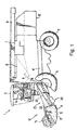
- an agricultural harvester 1 including a self-propelled vehicle having two wheel pairs 8 and 9, an engine 7 mechanically connected to rotate the wheels, a cab 2 where a vehicle operator 11 sits, and a header 12 for harvesting crops.
- Header 12 includes a reel assembly 13 for pulling crops into the header so that the crops are cut by a blade assembly 17 in the conventional manner and an auger 15 situated in an auger trough 14 for pushing cut crop material into the centre of the header.
- a cut crop elevator 21, or "feederhouse,” is located at the centre of the header 12 and is fed by the rotation of auger 15.
- cut crop material moves from auger 15 to (or a draper arrangement) elevator 21 where the cut crop material is carried by an elevator apron 23 from a front drum 22 to a rear drum 24 and into the rearward portions of the harvester 1.
- harvester 1 includes a threshing mechanism 3 and a grain/chaff separation system 4. Once the grain or other crop has been threshed and the chaff removed, the product crop is stored in tank 5. Tube 6 is used to unload the product crop and any chaff is discarded by the chaff spreader at the harvester outlet 10.
- the elevator 21 is fitted with a non-frangible object detector/ejector 35.
- Detector/ejector 35 serves to both detect and to remove any non-frangible objects from the flow of cut crop material passing through the elevator 21, thereby producing a flow of cut crop matter that is essentially free of foreign hard objects.
- detector/ejector 35 includes a ramp subassembly 55, a sensing plate 56, a sensor 58, a trap door 60, a door manipulation subassembly 64 and an ejector controller 74.
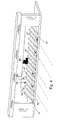
- the ramp subassembly 55 includes a plurality of ramp members 54 that are mounted to a top surface (not numbered) of a rigid and generally flat plate member 52 so as to extend upward therefrom.
- each of ramp members 54 in this embodiment includes a rigid, generally flat, triangular member having front and rear ends 77 and 79, respectively, an apex 78 located at a mid-point between the front and rear ends 77 and 79, front and rear ramp surfaces 76 and 82 that extend between the front end 77 and apex 78 and the rear end 79 and the apex 78, respectively, and a lower edge 81.
- ramp surface 76 forms an inclination angle ⁇ with lower edge 81 while rear ramp surface 82 forms an inclination angle ⁇ with lower edge 81.
- angle ⁇ is less than angle ⁇ .
- angle ⁇ is between 5 and 45 degrees while angle ⁇ is between 45 and 90 degrees or greater. In an advantageous embodiment angle ⁇ is approximately 30 degrees.
- ramp members 54 are substantially equi-spaced along the top surface of plate member 52, are separated by similarly dimensioned gaps, two of which are collectively identified by numeral 39 in Figure 5, and are juxtaposed so that their front ends are located along a front edge 41 of plate member 52.
- front edge 41 is adjacent member 50 and the top surface thereof is flush with transport surface 90 so that the front ends of ramp members 54 are adjacent and generally flush with transport surface 90.
- front ramp surfaces 76 are inclined with respect to transport surface 90 by the inclination angle ⁇ .
- the inclination angle ⁇ is 30 degrees
- ramp surfaces 76 ramp upward from transport surface 90 by 30 degrees.
- sensing plate 56 includes a generally flat, rigid and rectilinear sensing surface 75 and an oppositely facing undersurface (not labelled). Sensing plate 56 is mounted in an isolating fashion to plate 52 and other system components to minimize the transfer of harvester vibrations and noise to the plate. Ways to isolate sensing plates are well known in the art and therefore are not described here in detail.
- Sensor 58 is mounted to the undersurface of sensing plate 56 and, in at least some embodiments, includes a piezoelectric disc that generates signals when objects (e.g., non-frangible objects as well as crop material) impact sensing surface 75. Sensor 58 is linked to ejector controller 74.
- Sensor plate 56 is mounted adjacent ramp subassembly 55 and, in the illustrated embodiment of Figure 2, is mounted so that sensing surface 75 is parallel and aligned with the top surface of plate member 52.
- rear ramp surfaces 82 are inclined with respect to sensing surface 75 by the inclination angle ⁇ .
- the inclination angle ⁇ is 75°
- ramp surfaces 76 ramp upward from sensing surface 75 by 75°.
- the rear ramp surfaces 82 are ramped or inclined so that crop material can flow in a reverse direction when necessary.
- trap door 60 is positioned adjacent sensing plate 56 and is mounted at a pivot point 86 for pivotal movement between a closed position illustrated in Figure 2 and an open position illustrated in Figure 7.
- a top surface of door 60 guides material upward and to a second elevator transport member 62.
- door 60 allows material including non-frangible objects to drop out of the elevator passageway.
- Door manipulation subassembly 64 includes a solenoid 68 that is mounted between the undersurface of member 62 and door 60 and is controllable to open and close door 60.
- Ejector controller 74 is linked to solenoid 68 to control activation thereof.
- ejector controller 74 includes a discrimination circuit 113 operationally connected to sensor 58 and to a power supply 105 and to solenoid 68.
- Discrimination circuit 113 includes programmable amplifier 107, variable bandpass filter 109, variable threshold comparator 111, and a processor 115.
- Power supply 105 is electrically connected to the discrimination circuit to provide power to run the system.
- Sensor 58 is electrically connected to provide an object sensing input signal I1 to the programmable amplifier 107 of circuit 113.
- Amplifier 107 is electrically connected to bandpass filter 109 and amplifies input signal I1 to produce an amplified signal 12 that is inputted into bandpass filter 109.
- Bandpass filter 109 is electrically connected to comparator 111 and receives and filters signal 12 to produce a frequency filtered signal 13 corresponding to a predetermined and preferred frequency bandwidth.
- bandpass filter 109 generally filters out low frequency signals such as would be generated by soft organic crop material passing through feeder house 21 but transmits high frequency signals such as would be generated by non-frangible objects that impact the sensing surface 75 and that are to be separated from crop matter.
- bandpass filters may be used, in at least some applications it has been recognized that hardware-fixed bandwidth filters may be most suitable because such filters are relatively inexpensive.
- Variable threshold comparator 111 is electrically connected to filter 109, receives signal 13 from filter 109 and generates an ejection signal 14 only when the magnitude of signal 13 exceeds a minimum threshold amplitude.
- Processor 115 is electrically connected to comparator 111, receives signal 14 from comparator 111 and analyzes the received signal to determine if signal characteristics are indicative of a non-frangible object. When characteristics of signal 14 are indicative of a frangible object, processor 115 generates an activating signal A1 that is transmitted to solenoid 68.
- harvested material including crop and mixed in non-frangible objects 80 is transported along transport surface 90 toward ramp members 54. Once the material reaches members 54, smaller sized crop material and non-frangible objects are forced through the gaps 39 between members 54 while larger non-frangible objects and crop material is forced up the front ramp surfaces 76 of members 54. Eventually the large non-frangible objects are forced to the apexes 78 of members 54 and are pushed over the edges thereof.
- controller 74 causes trap door 60 to open and the object 80 is allowed to drop out of the resulting egress.
- ramp members 54 operate to perform two complimentary processes. First, ramp members 54 operate to separate relatively large non-frangible objects from at least the majority other harvested materials. Second, as the large non-frangible objects are separated, the objects are moved to positions vertically spaced above the sensing surface so that when the objects drop off the ramp members, the force with which the objects impact the sensing surface is increased and the resulting sensor signal can be more distinctive and easier to identify.
- a different type of ramp member 54a may include front and rear ramp surfaces 76a and 82a that are separated by a plateau surface 83a that is substantially parallel to a lower edge 81a where an apex (78) 78a is between front ramp surface 76a and surface 83a.
- the front ramp surface 76b of another ramp member type 54b may have an increasingly steep slope that terminates at an apex 78b.
- the rear ramp surfaces 82 may not be ramped in some applications and instead may simply form a 90° angle with lower edge 81 (see again Figure 6).
- angle ⁇ may be greater than 90° and an end portion of surface 76c near the apex 78c of the ramp members may overhang the sensing surface (not illustrated).
- a ramp subassembly 120 may include a plate member 122 that has a top surface 124 that angles downward from transport surface 90 and ramp members 126 may extend upward therefrom so that top ramp surfaces 128 akin to the front ramp surfaces 76 are substantially co-planar with transport surface 90.
- the invention could be used with a draper header where the auger is replaced by a conveyor belt to transport crop to the centre of the header and to a feeder house.
Landscapes
- Life Sciences & Earth Sciences (AREA)
- Environmental Sciences (AREA)
- Harvesting Machines For Specific Crops (AREA)
- Harvesting Machines For Root Crops (AREA)
Applications Claiming Priority (1)
| Application Number | Priority Date | Filing Date | Title |
|---|---|---|---|
| US11/187,367 US7207165B2 (en) | 2005-07-22 | 2005-07-22 | Non-frangible object detection method and apparatus for use with harvester |
Publications (2)
| Publication Number | Publication Date |
|---|---|
| EP1745690A1 true EP1745690A1 (de) | 2007-01-24 |
| EP1745690B1 EP1745690B1 (de) | 2012-03-14 |
Family
ID=37198862
Family Applications (1)
| Application Number | Title | Priority Date | Filing Date |
|---|---|---|---|
| EP06117591A Active EP1745690B1 (de) | 2005-07-22 | 2006-07-20 | Hartobjektdetektionsverfahren und -vorrichtung für Erntemaschine |
Country Status (3)
| Country | Link |
|---|---|
| US (1) | US7207165B2 (de) |
| EP (1) | EP1745690B1 (de) |
| AT (1) | ATE548909T1 (de) |
Cited By (2)
| Publication number | Priority date | Publication date | Assignee | Title |
|---|---|---|---|---|
| WO2015028854A1 (en) * | 2013-08-28 | 2015-03-05 | Agco Corporation | Combine with actuator controlled rock trap |
| CN110169255A (zh) * | 2018-02-19 | 2019-08-27 | 凯斯纽荷兰(中国)管理有限公司 | 可移除的螺旋输送器槽 |
Families Citing this family (19)
| Publication number | Priority date | Publication date | Assignee | Title |
|---|---|---|---|---|
| CA2572274C (en) * | 2006-12-29 | 2014-05-27 | Honey Bee Manufacturing Ltd. | Rock trap for combine header |
| US7993187B2 (en) * | 2007-05-23 | 2011-08-09 | Cnh America Llc | Foreign object detection and removal system for a combine harvester |
| JP6447672B2 (ja) * | 2017-06-30 | 2019-01-09 | 井関農機株式会社 | コンバイン |
| JP6421848B2 (ja) * | 2017-09-01 | 2018-11-14 | 井関農機株式会社 | コンバイン |
| JP6528836B2 (ja) * | 2017-12-29 | 2019-06-12 | 井関農機株式会社 | コンバイン |
| JP6519647B2 (ja) * | 2017-12-29 | 2019-05-29 | 井関農機株式会社 | コンバイン |
| JP6465246B2 (ja) * | 2018-10-01 | 2019-02-06 | 井関農機株式会社 | コンバイン |
| JP6813011B2 (ja) * | 2018-10-01 | 2021-01-13 | 井関農機株式会社 | コンバイン |
| JP6465245B2 (ja) * | 2018-10-01 | 2019-02-06 | 井関農機株式会社 | コンバイン |
| CN109287254B (zh) * | 2018-11-15 | 2020-08-28 | 雷沃重工股份有限公司 | 排石装置及收获机 |
| JP6652189B2 (ja) * | 2018-12-28 | 2020-02-19 | 井関農機株式会社 | コンバイン |
| JP6687870B2 (ja) * | 2019-02-08 | 2020-04-28 | 井関農機株式会社 | コンバイン |
| JP6687871B2 (ja) * | 2019-03-06 | 2020-04-28 | 井関農機株式会社 | コンバイン |
| JP6704185B2 (ja) * | 2019-03-29 | 2020-06-03 | 井関農機株式会社 | コンバイン |
| JP6704186B2 (ja) * | 2019-03-29 | 2020-06-03 | 井関農機株式会社 | コンバイン |
| AR118546A1 (es) * | 2019-04-02 | 2021-10-20 | Cnh Ind America Llc | Puerta remota de limpieza de una plataforma de alimentación para un cabezal |
| US20220304236A1 (en) * | 2019-06-26 | 2022-09-29 | Jakob Sørensen Ip Aps | A combine harvester and a method for threshing harvested crop material |
| US11570951B2 (en) * | 2019-12-19 | 2023-02-07 | Deere & Company | Forage harvester with processing component protection |
| DE102024108695A1 (de) * | 2024-03-27 | 2025-10-02 | Claas Selbstfahrende Erntemaschinen Gmbh | Landwirtschaftliche Erntemaschine |
Citations (4)
| Publication number | Priority date | Publication date | Assignee | Title |
|---|---|---|---|---|
| US4275546A (en) | 1980-01-04 | 1981-06-30 | Sperry Corporation | Stone discriminator |
| GB2072475A (en) * | 1980-03-27 | 1981-10-07 | Sperry Corp | Stone etc detectors |
| FR2485326A1 (fr) * | 1980-06-25 | 1981-12-31 | Claas Ohg | Moissonneuse, notamment du type ramasseuse-hacheuse |
| US6298641B1 (en) * | 1999-04-12 | 2001-10-09 | New Holland North America, Inc. | Stone ejection for a feederhouse on an agriculture combine |
Family Cites Families (14)
| Publication number | Priority date | Publication date | Assignee | Title |
|---|---|---|---|---|
| US1806928A (en) | 1931-05-26 | Bine habvesteb cobpob ation | ||
| US2768627A (en) | 1953-11-10 | 1956-10-30 | Ervin H Wolgast | Stone deflecting means for a cylinder and concave type thresher |
| US3675660A (en) | 1971-05-03 | 1972-07-11 | Massey Ferguson Ind Ltd | Combine stone trap door |
| US3805798A (en) | 1972-11-08 | 1974-04-23 | Massey Ferguson Ind Ltd | Combine harvester protection system |
| US4305244A (en) | 1980-03-27 | 1981-12-15 | Sperry Corporation | Feeder house design for a combine |
| US4322933A (en) | 1980-08-25 | 1982-04-06 | Sperry Corporation | Stone trapdoor trip mechanism |
| US4344074A (en) | 1981-04-02 | 1982-08-10 | Sperry Corporation | Magnetic field producing apparatus |
| US4353199A (en) | 1981-04-15 | 1982-10-12 | Sperry Corporation | Stone detector for harvesting machines |
| US4720962A (en) | 1982-07-29 | 1988-01-26 | National Research Development Corporation | Apparatus for picking up and conveying crop or other material |
| US4707972A (en) | 1985-06-19 | 1987-11-24 | New Holland Inc. | Movable feeder floor for combines |
| US5443421A (en) | 1993-07-20 | 1995-08-22 | Heintzman; Rick | Rock discharge assembly for hay crusher |
| US5462487A (en) | 1994-09-23 | 1995-10-31 | Farley; Scott A. | Rock guard for a combine |
| US6430903B1 (en) | 2000-07-14 | 2002-08-13 | Neil Christiansen | Nonmetallic debris detector for harvester equipment |
| US6601372B1 (en) | 2002-02-22 | 2003-08-05 | New Holland North America, Inc. | Stone detection method and apparatus for harvester |
-
2005
- 2005-07-22 US US11/187,367 patent/US7207165B2/en not_active Expired - Lifetime
-
2006
- 2006-07-20 AT AT06117591T patent/ATE548909T1/de active
- 2006-07-20 EP EP06117591A patent/EP1745690B1/de active Active
Patent Citations (5)
| Publication number | Priority date | Publication date | Assignee | Title |
|---|---|---|---|---|
| US4275546A (en) | 1980-01-04 | 1981-06-30 | Sperry Corporation | Stone discriminator |
| GB2072475A (en) * | 1980-03-27 | 1981-10-07 | Sperry Corp | Stone etc detectors |
| US4294062A (en) | 1980-03-27 | 1981-10-13 | Sperry Corporation | Sensing bar |
| FR2485326A1 (fr) * | 1980-06-25 | 1981-12-31 | Claas Ohg | Moissonneuse, notamment du type ramasseuse-hacheuse |
| US6298641B1 (en) * | 1999-04-12 | 2001-10-09 | New Holland North America, Inc. | Stone ejection for a feederhouse on an agriculture combine |
Cited By (3)
| Publication number | Priority date | Publication date | Assignee | Title |
|---|---|---|---|---|
| WO2015028854A1 (en) * | 2013-08-28 | 2015-03-05 | Agco Corporation | Combine with actuator controlled rock trap |
| CN110169255A (zh) * | 2018-02-19 | 2019-08-27 | 凯斯纽荷兰(中国)管理有限公司 | 可移除的螺旋输送器槽 |
| CN110169255B (zh) * | 2018-02-19 | 2022-06-28 | 凯斯纽荷兰(中国)管理有限公司 | 可移除的螺旋输送器槽 |
Also Published As
| Publication number | Publication date |
|---|---|
| ATE548909T1 (de) | 2012-03-15 |
| US7207165B2 (en) | 2007-04-24 |
| US20070028576A1 (en) | 2007-02-08 |
| EP1745690B1 (de) | 2012-03-14 |
Similar Documents
| Publication | Publication Date | Title |
|---|---|---|
| EP1745690B1 (de) | Hartobjektdetektionsverfahren und -vorrichtung für Erntemaschine | |
| EP1731020B1 (de) | Verfahren und Apparat zur Detektion von Steinen in Erntemaschinen | |
| EP1044597B1 (de) | Detektion und Auswurf von Steinen für Schrägfördergehäuse eines Mähdreschers | |
| US4275546A (en) | Stone discriminator | |
| EP1344444B1 (de) | Einrichtung zur Erfassung des Vorhandenseins eines Gutstroms in einer Erntemaschine | |
| EP4144202B1 (de) | Aktiver verlustmonitor für eine erntemaschine | |
| CN109417899A (zh) | 在储存收割模式下控制收割机的升运机速度的系统和方法 | |
| US20060277883A1 (en) | Acoustic stone detection for a feederhouse on an agricultural combine | |
| EP1632130B1 (de) | Empfindlichkeitseinstellung für ein System zur Detektion von Steinen | |
| US4294062A (en) | Sensing bar | |
| EP0037147B1 (de) | Zuführvorrichtung für Erntemaschinen | |
| EP1338189B1 (de) | Verfahren und Apparat zur Detektion von Steinen in Dreschmaschinen | |
| JP2018061457A (ja) | コンバイン | |
| US6415592B1 (en) | Harvester apparatus and method for separating ripe fruit from harvested plants | |
| EP1731019B1 (de) | Akustische Detektion von Steinen für ein Schrägfördergehäuse eines Mähdreschers | |
| DE19850062C2 (de) | Schutzeinrichtung für Erntemaschinen | |
| US20240138303A1 (en) | Corn header row unit control system | |
| JP7580369B2 (ja) | 農作物回収機 | |
| EP4413849A1 (de) | System zur erkennung gebrochener paddel für einen aufzug eines mähdreschers | |
| US12628737B2 (en) | Broken paddle detection system for elevator of combine harvester | |
| EP4353070B1 (de) | Dämpfungssysteme und verfahren zur aufprallerfassung auf einem landwirtschaftlichen erntevorsatz | |
| US20260000022A1 (en) | Sensor arrangement for detecting grains in a material stream containing grains and non-grain components in a combine harvester | |
| JP2018166487A (ja) | トウモロコシ収穫機 | |
| CN121694119A (zh) | 农业收割机的作物损失监视系统 | |
| JPH10276561A (ja) | 脱穀装置 |
Legal Events
| Date | Code | Title | Description |
|---|---|---|---|
| PUAI | Public reference made under article 153(3) epc to a published international application that has entered the european phase |
Free format text: ORIGINAL CODE: 0009012 |
|
| AK | Designated contracting states |
Kind code of ref document: A1 Designated state(s): AT BE BG CH CY CZ DE DK EE ES FI FR GB GR HU IE IS IT LI LT LU LV MC NL PL PT RO SE SI SK TR |
|
| AX | Request for extension of the european patent |
Extension state: AL BA HR MK YU |
|
| 17P | Request for examination filed |
Effective date: 20070724 |
|
| 17Q | First examination report despatched |
Effective date: 20070824 |
|
| AKX | Designation fees paid |
Designated state(s): AT BE BG CH CY CZ DE DK EE ES FI FR GB GR HU IE IS IT LI LT LU LV MC NL PL PT RO SE SI SK TR |
|
| GRAP | Despatch of communication of intention to grant a patent |
Free format text: ORIGINAL CODE: EPIDOSNIGR1 |
|
| RTI1 | Title (correction) |
Free format text: NON-FRANGIBLE OBJECT DETECTION METHOD AND APPARATUS FOR USE WITH HARVESTER |
|
| GRAS | Grant fee paid |
Free format text: ORIGINAL CODE: EPIDOSNIGR3 |
|
| GRAA | (expected) grant |
Free format text: ORIGINAL CODE: 0009210 |
|
| AK | Designated contracting states |
Kind code of ref document: B1 Designated state(s): AT BE BG CH CY CZ DE DK EE ES FI FR GB GR HU IE IS IT LI LT LU LV MC NL PL PT RO SE SI SK TR |
|
| REG | Reference to a national code |
Ref country code: GB Ref legal event code: FG4D |
|
| REG | Reference to a national code |
Ref country code: AT Ref legal event code: REF Ref document number: 548909 Country of ref document: AT Kind code of ref document: T Effective date: 20120315 Ref country code: CH Ref legal event code: EP |
|
| REG | Reference to a national code |
Ref country code: IE Ref legal event code: FG4D |
|
| REG | Reference to a national code |
Ref country code: DE Ref legal event code: R096 Ref document number: 602006028141 Country of ref document: DE Effective date: 20120510 |
|
| REG | Reference to a national code |
Ref country code: NL Ref legal event code: VDEP Effective date: 20120314 |
|
| PG25 | Lapsed in a contracting state [announced via postgrant information from national office to epo] |
Ref country code: LT Free format text: LAPSE BECAUSE OF FAILURE TO SUBMIT A TRANSLATION OF THE DESCRIPTION OR TO PAY THE FEE WITHIN THE PRESCRIBED TIME-LIMIT Effective date: 20120314 |
|
| LTIE | Lt: invalidation of european patent or patent extension |
Effective date: 20120314 |
|
| PG25 | Lapsed in a contracting state [announced via postgrant information from national office to epo] |
Ref country code: GR Free format text: LAPSE BECAUSE OF FAILURE TO SUBMIT A TRANSLATION OF THE DESCRIPTION OR TO PAY THE FEE WITHIN THE PRESCRIBED TIME-LIMIT Effective date: 20120615 Ref country code: FI Free format text: LAPSE BECAUSE OF FAILURE TO SUBMIT A TRANSLATION OF THE DESCRIPTION OR TO PAY THE FEE WITHIN THE PRESCRIBED TIME-LIMIT Effective date: 20120314 Ref country code: LV Free format text: LAPSE BECAUSE OF FAILURE TO SUBMIT A TRANSLATION OF THE DESCRIPTION OR TO PAY THE FEE WITHIN THE PRESCRIBED TIME-LIMIT Effective date: 20120314 |
|
| REG | Reference to a national code |
Ref country code: AT Ref legal event code: MK05 Ref document number: 548909 Country of ref document: AT Kind code of ref document: T Effective date: 20120314 |
|
| PG25 | Lapsed in a contracting state [announced via postgrant information from national office to epo] |
Ref country code: CY Free format text: LAPSE BECAUSE OF FAILURE TO SUBMIT A TRANSLATION OF THE DESCRIPTION OR TO PAY THE FEE WITHIN THE PRESCRIBED TIME-LIMIT Effective date: 20120314 |
|
| PG25 | Lapsed in a contracting state [announced via postgrant information from national office to epo] |
Ref country code: SE Free format text: LAPSE BECAUSE OF FAILURE TO SUBMIT A TRANSLATION OF THE DESCRIPTION OR TO PAY THE FEE WITHIN THE PRESCRIBED TIME-LIMIT Effective date: 20120314 Ref country code: CZ Free format text: LAPSE BECAUSE OF FAILURE TO SUBMIT A TRANSLATION OF THE DESCRIPTION OR TO PAY THE FEE WITHIN THE PRESCRIBED TIME-LIMIT Effective date: 20120314 Ref country code: SI Free format text: LAPSE BECAUSE OF FAILURE TO SUBMIT A TRANSLATION OF THE DESCRIPTION OR TO PAY THE FEE WITHIN THE PRESCRIBED TIME-LIMIT Effective date: 20120314 Ref country code: IS Free format text: LAPSE BECAUSE OF FAILURE TO SUBMIT A TRANSLATION OF THE DESCRIPTION OR TO PAY THE FEE WITHIN THE PRESCRIBED TIME-LIMIT Effective date: 20120714 Ref country code: PL Free format text: LAPSE BECAUSE OF FAILURE TO SUBMIT A TRANSLATION OF THE DESCRIPTION OR TO PAY THE FEE WITHIN THE PRESCRIBED TIME-LIMIT Effective date: 20120314 Ref country code: EE Free format text: LAPSE BECAUSE OF FAILURE TO SUBMIT A TRANSLATION OF THE DESCRIPTION OR TO PAY THE FEE WITHIN THE PRESCRIBED TIME-LIMIT Effective date: 20120314 Ref country code: BE Free format text: LAPSE BECAUSE OF FAILURE TO SUBMIT A TRANSLATION OF THE DESCRIPTION OR TO PAY THE FEE WITHIN THE PRESCRIBED TIME-LIMIT Effective date: 20120314 Ref country code: RO Free format text: LAPSE BECAUSE OF FAILURE TO SUBMIT A TRANSLATION OF THE DESCRIPTION OR TO PAY THE FEE WITHIN THE PRESCRIBED TIME-LIMIT Effective date: 20120314 |
|
| PG25 | Lapsed in a contracting state [announced via postgrant information from national office to epo] |
Ref country code: PT Free format text: LAPSE BECAUSE OF FAILURE TO SUBMIT A TRANSLATION OF THE DESCRIPTION OR TO PAY THE FEE WITHIN THE PRESCRIBED TIME-LIMIT Effective date: 20120716 Ref country code: SK Free format text: LAPSE BECAUSE OF FAILURE TO SUBMIT A TRANSLATION OF THE DESCRIPTION OR TO PAY THE FEE WITHIN THE PRESCRIBED TIME-LIMIT Effective date: 20120314 |
|
| PLBE | No opposition filed within time limit |
Free format text: ORIGINAL CODE: 0009261 |
|
| STAA | Information on the status of an ep patent application or granted ep patent |
Free format text: STATUS: NO OPPOSITION FILED WITHIN TIME LIMIT |
|
| PG25 | Lapsed in a contracting state [announced via postgrant information from national office to epo] |
Ref country code: DK Free format text: LAPSE BECAUSE OF FAILURE TO SUBMIT A TRANSLATION OF THE DESCRIPTION OR TO PAY THE FEE WITHIN THE PRESCRIBED TIME-LIMIT Effective date: 20120314 Ref country code: AT Free format text: LAPSE BECAUSE OF FAILURE TO SUBMIT A TRANSLATION OF THE DESCRIPTION OR TO PAY THE FEE WITHIN THE PRESCRIBED TIME-LIMIT Effective date: 20120314 Ref country code: NL Free format text: LAPSE BECAUSE OF FAILURE TO SUBMIT A TRANSLATION OF THE DESCRIPTION OR TO PAY THE FEE WITHIN THE PRESCRIBED TIME-LIMIT Effective date: 20120314 |
|
| 26N | No opposition filed |
Effective date: 20121217 |
|
| PG25 | Lapsed in a contracting state [announced via postgrant information from national office to epo] |
Ref country code: IT Free format text: LAPSE BECAUSE OF FAILURE TO SUBMIT A TRANSLATION OF THE DESCRIPTION OR TO PAY THE FEE WITHIN THE PRESCRIBED TIME-LIMIT Effective date: 20120314 Ref country code: MC Free format text: LAPSE BECAUSE OF NON-PAYMENT OF DUE FEES Effective date: 20120731 |
|
| REG | Reference to a national code |
Ref country code: CH Ref legal event code: PL |
|
| REG | Reference to a national code |
Ref country code: DE Ref legal event code: R097 Ref document number: 602006028141 Country of ref document: DE Effective date: 20121217 |
|
| PG25 | Lapsed in a contracting state [announced via postgrant information from national office to epo] |
Ref country code: ES Free format text: LAPSE BECAUSE OF FAILURE TO SUBMIT A TRANSLATION OF THE DESCRIPTION OR TO PAY THE FEE WITHIN THE PRESCRIBED TIME-LIMIT Effective date: 20120625 Ref country code: CH Free format text: LAPSE BECAUSE OF NON-PAYMENT OF DUE FEES Effective date: 20120731 Ref country code: LI Free format text: LAPSE BECAUSE OF NON-PAYMENT OF DUE FEES Effective date: 20120731 |
|
| REG | Reference to a national code |
Ref country code: IE Ref legal event code: MM4A |
|
| PG25 | Lapsed in a contracting state [announced via postgrant information from national office to epo] |
Ref country code: BG Free format text: LAPSE BECAUSE OF FAILURE TO SUBMIT A TRANSLATION OF THE DESCRIPTION OR TO PAY THE FEE WITHIN THE PRESCRIBED TIME-LIMIT Effective date: 20120614 Ref country code: IE Free format text: LAPSE BECAUSE OF NON-PAYMENT OF DUE FEES Effective date: 20120720 |
|
| REG | Reference to a national code |
Ref country code: DE Ref legal event code: R082 Ref document number: 602006028141 Country of ref document: DE Representative=s name: PATENTANWAELTE WALLACH, KOCH & PARTNER, DE |
|
| PG25 | Lapsed in a contracting state [announced via postgrant information from national office to epo] |
Ref country code: TR Free format text: LAPSE BECAUSE OF FAILURE TO SUBMIT A TRANSLATION OF THE DESCRIPTION OR TO PAY THE FEE WITHIN THE PRESCRIBED TIME-LIMIT Effective date: 20120314 |
|
| PG25 | Lapsed in a contracting state [announced via postgrant information from national office to epo] |
Ref country code: LU Free format text: LAPSE BECAUSE OF NON-PAYMENT OF DUE FEES Effective date: 20120720 |
|
| REG | Reference to a national code |
Ref country code: DE Ref legal event code: R081 Ref document number: 602006028141 Country of ref document: DE Owner name: CNH INDUSTRIAL BELGIUM NV, BE Free format text: FORMER OWNER: CNH BELGIUM NV, ZEDELGEM, BE Effective date: 20140428 Ref country code: DE Ref legal event code: R082 Ref document number: 602006028141 Country of ref document: DE Representative=s name: PATENTANWAELTE WALLACH, KOCH & PARTNER, DE Effective date: 20140428 Ref country code: DE Ref legal event code: R081 Ref document number: 602006028141 Country of ref document: DE Owner name: CNH INDUSTRIAL BELGIUM NV, BE Free format text: FORMER OWNER: CNH BELGIUM NV, ZEDELGEM, BE Effective date: 20120316 Ref country code: DE Ref legal event code: R082 Ref document number: 602006028141 Country of ref document: DE Representative=s name: PATENTANWAELTE WALLACH, KOCH, DR. HAIBACH, FEL, DE Effective date: 20140428 |
|
| PG25 | Lapsed in a contracting state [announced via postgrant information from national office to epo] |
Ref country code: HU Free format text: LAPSE BECAUSE OF FAILURE TO SUBMIT A TRANSLATION OF THE DESCRIPTION OR TO PAY THE FEE WITHIN THE PRESCRIBED TIME-LIMIT Effective date: 20060720 |
|
| REG | Reference to a national code |
Ref country code: FR Ref legal event code: CD Owner name: CNH INDUSTRIAL BELGIUM NV Effective date: 20140725 |
|
| REG | Reference to a national code |
Ref country code: FR Ref legal event code: PLFP Year of fee payment: 11 |
|
| REG | Reference to a national code |
Ref country code: FR Ref legal event code: PLFP Year of fee payment: 12 |
|
| REG | Reference to a national code |
Ref country code: FR Ref legal event code: PLFP Year of fee payment: 13 |
|
| PGFP | Annual fee paid to national office [announced via postgrant information from national office to epo] |
Ref country code: GB Payment date: 20190724 Year of fee payment: 14 |
|
| REG | Reference to a national code |
Ref country code: DE Ref legal event code: R084 Ref document number: 602006028141 Country of ref document: DE |
|
| REG | Reference to a national code |
Ref country code: DE Ref legal event code: R082 Ref document number: 602006028141 Country of ref document: DE Representative=s name: MEISSNER BOLTE PATENTANWAELTE RECHTSANWAELTE P, DE |
|
| GBPC | Gb: european patent ceased through non-payment of renewal fee |
Effective date: 20200720 |
|
| PG25 | Lapsed in a contracting state [announced via postgrant information from national office to epo] |
Ref country code: GB Free format text: LAPSE BECAUSE OF NON-PAYMENT OF DUE FEES Effective date: 20200720 |
|
| PGFP | Annual fee paid to national office [announced via postgrant information from national office to epo] |
Ref country code: DE Payment date: 20250728 Year of fee payment: 20 |
|
| PGFP | Annual fee paid to national office [announced via postgrant information from national office to epo] |
Ref country code: FR Payment date: 20250725 Year of fee payment: 20 |